FMT Swiss AG mobiSERVE Instruction Manual

81 231 932 A801 GB
OPERATING INSTRUCTIONS
AND SAFETY NOTES
mobiSERVE
Mobile with battery

2
GB Operating instructions - mobiSERVE
FMT Swiss AG
This documentation is exclusively intended for the operating company and their sta.
Without our written consent, the content of this documentation (textes, gures, drawings,
charts, diagrams etc. ), must not be duplicated or distributed, neither in full or in part, utilized
for the purpose of competition or passed on/made availabe to third parties.
FMT Swiss AG
Fluid Management Technologies Swiss AG
Gewerbestraße 6
6330 Cham / Schweiz
Tel. +41 41 712 05 37
Fax +41 41 720 26 21
Email: info@fmtag.com
Internet: www.fmtag.com
Operating instructions translation
Date of issue: 05/2017
We reserve the right to make design and product modications, which serve to improve the
product.

3
Operating instructions - mobiSERVE
GB
Table of Contents
1. Introduction ________________________________________________________________________4
1.1 Preface ____________________________________________________________________________4
1.2 Obligations of the personnel ___________________________________________________________4
1.3 Symbols in this manual _______________________________________________________________4
1.3.1. Structure of the warning notes _________________________________________________________4
1.3.2. Hazard symbols _____________________________________________________________________5
1.3.3. General symbols _____________________________________________________________________5
2. Safety instructions ___________________________________________________________________5
2.1 Authorized personnel_________________________________________________________________6
2.2 Notes on cleaning and repair___________________________________________________________6
2.3 Intended conditions of use ____________________________________________________________6
2.4 Risks when handling the mobiSERVE ____________________________________________________7
3. Transport and in-house transport _______________________________________________________7
4. Design and functional description ______________________________________________________8
5. Commissioning and operation _________________________________________________________9
5.1 Filling operation ____________________________________________________________________11
5.2 Adjusting the ow rate_______________________________________________________________11
6. Technical data______________________________________________________________________11
7. Assembly__________________________________________________________________________12
8. Daily use __________________________________________________________________________12
8.1 Discharge in normal mode____________________________________________________________13
8.1.1. Resetting the partial amount__________________________________________________________13
8.1.2. Resetting the resettable total amount RESET TOTAL _______________________________________14
8.1.3. Discharge with display of the current ow rate (Flow Rate Mode) ____________________________14
8.1.4. Resetting the partial amount__________________________________________________________15
9. Calibration ________________________________________________________________________15
9.1 Denition _________________________________________________________________________15
9.2 Why to calibrate ____________________________________________________________________15
9.3 Calibration mode ___________________________________________________________________16
9.4 Display of the current calibration factor and, if required, resetting the manufacturer's factor ______16
9.4.1. Calibration during operation _________________________________________________________17
9.4.2. Calibration procedure during operation ________________________________________________18
9.4.3. Direct change of the K FACTOR ________________________________________________________20
10. Conguration of the mobiServe counter ________________________________________________22
11. Preventive maintenance _____________________________________________________________23
12. Troubleshooting ____________________________________________________________________23
13. Maintenance ______________________________________________________________________24
14. Repair/Service______________________________________________________________________24
15. Disposal___________________________________________________________________________24
16. EC Declaration of Conformity _________________________________________________________25
17. Exploded view of the mobiSERVE 200 l__________________________________________________26
18. Exploded view of the mobiSERVE 60 l ___________________________________________________28

4
GB Operating instructions - mobiSERVE
1. Introduction
1.1 Preface
Please carefully read these operating instructions and observe in particular all safety notes!
Our sta will be pleased to provide support if you have any questions about the product.
Yours sincerely, FMT Swiss AG
1.2 Obligations of the personnel
Before they start to work, all persons who are entrusted with work with the mobiSERVE are obliged:
– to follow all applicable regulations on occupational safety and accident prevention.
– to read and to comply with all safety instructions and warning notes contained in these operating
instructions.
Please observe the following instructions in the interest of all concerned:
Refrain from any unsafe working methods!
Adhere to all hazard and warning notes contained in this manual!
In addition to this documentation, keep to all generally accepted safety rules, legal provisions as
well as all other binding rules regarding occupational safety, accident prevention and environmental
protection!
Wear appropriate protective clothing in accordance with the work to be done!
Perform only work for which you have been suciently trained and instructed!
Only genuine spare parts as well as original tools and auxiliaries of the manufacturer are allowed to be
used in order to ensure the functional safety and maintain the warranty coverage.
1.3 Symbols in this manual
1.3.1 Structure of the warning notes
The warning notes have the following structure:
SIGNAL WORD
Type and source of the hazard
Consquences of non-compliance with the notes
Measures to avoid that risk
Depending on the danger level, dierent signal words are used:
Signal word Danger level Consequences of non-compliance
DANGER Imminent threat
of danger
Death or serious bodily injury
WARNING Possible threat
of danger
Death or serious bodily injury
CAUTION Possibly dangerous
situation
Minor bodily injury
ATTENTION Possibly dangerous
situation
Damage to material property

5
Operating instructions - mobiSERVE
GB
NOTE
Indicates further information or tips which facilitate work.
1.3.2 Hazard symbols
Symbol Meaning
General hazard symbol. The warning note marked in this way contains sup-
plementary information on the type of hazard.
This symbol warns of dangerous electrical voltages.
This symbol warns of a hazardous explosive atmosphere.
1.3.3 General symbols
Symbol Meaning
A small black square indicates the work you have to perform.
–The dash denotes lists.
aThe arrow identies cross-references.
If cross-references to other chapters are required within the text, the expres-
sion is shortened for reasons of clarity.
Example: aChapter 2 Safety instructions
This means: please refer to chapter 2 for the safety instructions.
2. Safety instructions
Various dangers may occur if the mobiSERVE is improperly handled during installation, commissioning
and daily operation.
WARNING
Risk of injury and damage to material property because of improper
handling
Hold the manual at the disposal of the operating sta at the usage site of the
unit. Country-specic safety measures and accident prevention regulations
must be observed.
6
GB Operating instructions - mobiSERVE
2.1 Authorized personnel
Only qualied and authorized persons are allowed to operate and to work on the mobiSERVE.
Persons are qualied if they are, due to their training, experience, instruction and knowledge of the
relevant standards, able to assess assigned tasks and to identify potentially hazardous situations.
These persons must have been authorized by the person responsible for the safety of the unit and must
be able to identify and to avoid potential dangers.
All persons charged with installation, operation, maintenance and repair work, must have read and
understood this operation manual.
A copy of this operating manual must be stored permanently and ready at hand at the place of usage
of the unit.
2.2 Notes on cleaning and repair
WARNING
Wear suitable gloves as a protection against long-term skin contact with
urea solution.
The mobiSERVE is allowed to be cleaned by instructed personnel only.
When handling urea solutions, adhere to the information provided on the
material data safety sheet.
2.3 Intended conditions of use
The mobiSERVE urea conveying system has been designed for conveying urea solutions (urea, AdBlue®)
or water from mobile tanks into containers provided for this purpose, for example vehicle tanks.
The urea conveying system is operated independently of the mains power.
The mobiSERVE is suitable for use in workshops.
WARNING
Never use it to deliver explosive uids such as gasoline or other u-
ids with similar ashpoints!
The mobiSERVE is only allowed to be connected to an appropriate voltage source (see type plate).
Conveying caustic or other hazardous chemical or biological substances is forbidden.
The use in the food industry is forbidden.
Any departure from the usage stipulations (other uid media, use of force) or user modications
(changes, use of non-original parts) can be dangerous and is considered as non-intended usage.
The user is liable for any damage resulting from non-intended use.
During repairs to any electrical components, the appropriate safety and test requirements are to be
observed.
Only genuine replacement parts are to be used for any repairs, because otherwise the warranty will be
invalidated.
2.4 Risks when handling the mobiSERVE
Any application beyond the intended use can lead to hazardous situations and shall be regarded as non-
intended use.

7
Operating instructions - mobiSERVE
GB
DANGER
Risk of injury and material damage because of improper installation, elec-
tric current or contaminated media
Risk of injury from stumbling or falling because of improperly laid
power lines.
Moving the device with defective castors and/or defective accessories
is forbidden!
If the power cable is not used, this one must be disconnected from the
mobiSERVE and kept in a safe place.
Never work on a pump that is running
Mount or remove attachments and accessories only when the pump is
switched o.
For your own safety, disconnect the pump in addition from the power supply.
Do not pump contaminated uids
Take special care to ensure that there are no contaminants in the uid to
be pumped.
Damaged attachments and accessories can lead to personal injury and
material damage
Attachments and accessories must be checked for wear, splits or other
damage throughout its period of use.
Damaged accessories and attachments must be replaced immediately.
With reference to the period of use, please note the details in ZH 1A45.4.2
or DIN 20066 Part 5.3.2.
Escaping liquids can cause environmental harm
Comply with the stipulations of the German Water Resources Act (WHG) and
of the Plant Regulations of the German federal states.
3. Transport and in-house transport
All lifting and transport work may only be done by qualied and suitably instructed personnel. Only use
the provided attachment points as well as approved lifting gear and slings to lift the mobiSERVE.
Use appropriate means to secure the mobiSERVE and the related individual parts on a means of
transport / transport pallet.
It is not allowed to transport the urea conveying system with tted urea dispensing container!
Urea dispensing containers / urea cans must be transported separately. The manufacturer's transport
provisions must be observed.
CAUTION
It is forbidden to transport the mobiSERVE with plugged-in power cord.
For a transport of the battery, the poles must be protected by caps and
insulating tape.
WARNING!
Castors/tyres are provided for in-house transports. When moving the
device, check to ensure that all aps and doors are properly closed and that
the urea container is safely placed on the mobiSERVE and is secured against
falling!

8
GB Operating instructions - mobiSERVE
4. Design and functional description
The mobiSERVE is a mobile relling vehicle featuring an electronic counter with digital display.
The built-in pump is operated by an on-board lead accumulator. An integrated charger is provided to
recharge the battery. The battery charge level is indicated on the control panel. The quantity delivered
is measured by means of an electronic system featuring an oval gear meter.
A rotary knob allows to continuously adjust the ow rate in a dened range.
The LCD (liquid cristal display) of the mobiSERVEs is equipped with two numerical registers and various
screens which only appear if needed by the current function.
Legend:
1. Register of the partial amount ( 5 digits with oating point: 0.000+99999), indicating the quantity
issued since the last actuation of the RESET key
2. Display of the calibration modality
3. Register of the total amount (6 digits with oating point 0.0 - 999999x10/x100) that can show two
types of total amounts:
3.1 Total amount not resettable to zero (TOTAL)
3.2 Total amount resettable to zero (RESET TOTAL)
4. Display of the multiplication factor of the total amount (x10/x100)
5. Display of the total amount type (TOTAL/RESET TOTAL)
Flow control Battery charge level
On / O
Flow rate / discharge amoun
Display LCD

9
Operating instructions - mobiSERVE
GB
6. Display of the total amount measuring unit; L = Liters; GAL = Gallons
7. Flow rate display
8. Display of the partial amount measuring unit:
QTS = Quarters; PTS = Pints; L = Liters; GAL = Gallons;
The mobiSERVE is equipped with two push buttons (RESET and TOTAL) whereby each of them carries
out two main functions. In combination, these two buttons perform other auxiliary functions.
Main functions:
1. RESET-Taste:
to reset the partial amount register and the resettable total amount register
RESET TOTAL.
2. TOTAL key:
to call up the calibration mode of the unit. In combination, both keys allow to call up the
conguration mode, where the measuring unit desired can be entered.
Main switch On/O
Upon actuation of the main switch, the pump starts to work. The battery charge indicator shows the-
battery status, and in the LCD display, the daily amount is indicated.
The pump's maximum duty cycle is 5 minutes. This prevents an uncontrolled pump operation, if acci-
dentally the main switch has not been switched o.
When the unit is turned o and on again, the pump restarts to work. The LCD display remains active for
30 minutes after the main switch has been turned o.
Measuring chamber
The measuring chamber is located in the middle part of the unit.
The measuring chamber is equipped with oval gears. When rotating, these oval gears produce electri-
cal impulses which are processed by the microprocessor on the electronic card.
The microprocessor works with a calibration factor (i. e. with a "weight" allocated to each impulse). The
impulses produced during rotation are converted in uid volumes expressed in the previously determi-
ned measuring unit and are displayed in the partial and total amount registers on the LCD screen.
All mobiSERVEs leave the factory with a calibration factor, called FACTORY K FACTOR, which amounts
to approx. 1,000. The unit can be calibrated in order to optimally adjust the counter to the uid to be
measured.
It is possible at any time to return to the calibration set by the manufacturer.
Battery
The mobiSERVE is powered by a maintenance-free 12 V lead accumulator.
The battery compartment is located in the housing.
To replace the battery, the housing cover must be removed.
5. Commissioning and operation
Check the mobiSERVE and the assembled attachments for completeness and damage. Replace any
damaged parts immediately and never use a damaged pump.
CAUTION
Before working on the device, apply the locking brake of the castors.

10
GB Operating instructions - mobiSERVE
CAUTION
Never operate the mobiSERVE without a uid for more than 2 minutes.
Your urea pump may be damaged by dry running.
It is forbidden to operate the unit with defective equipment.
Press the nozzle valve lever up according to the delivery rate desired or actuate the lock.
Operate the rocker switch to turn the mobiSERVE on.
Placing and lling the barrel:
Suitable devices are to be used to lift the urea container onto the space provided for it on the mobi-
SERVE. Check to ensure that the whole surface is used, because otherwise there is the risk that the urea
container may fall backwards out of the trolley. In addition, the urea container must be secured against
falling out.
200 liter mobiSERVE 25 352
Place the 200 l barrel on the load area of the trolley. Actuate the parking brakes
of the two castors in order to ensure a secure and safe standing position.
Insert the suction line into the barrel and connect the screw coupling and the
barrel thread.
Tighten the union nut in order to connect the preassembled hose and the
suction line in the barrel. Check to ensure that the O-rings are not damaged at
the connection.
For an exchange of barrels, proceed in reverse order.
60 liter mobiSERVE 25 353
The 60 l trolley is equipped with a plastic container. The suction hose and the
connecting hose are already preassembled in the barrel.
You have the possibility to ll the container by an external lling operation. The
suction hose is equipped with a SEC adapter, so that the container can be lled
by means of the pump in the trolley.
To do this, connect the SEC adapter to the existing IBC container.
Open the red screw cap at the trolley container and insert the nozzle into this
opening.
Turn the rotary knob for ow control to 100 %.
Switch the main switch on. The pump starts to work now.
Open the nozzle valve and actuate the lock. The nozzle valve will automatically
close when the container is full.
Then, shut o the main switch and reconnect the SEC adapter to the suction
line of the trolley container.
NOTE
In case of a relling or after an exchange of a barrel, completely bleed the air
from the system, in order to avoid measuring errors in the electronic counter
system.
To do this, open the second opening of the trolley container and insert
the nozzle valve. Perform a lling operation as described under paragraph
5.1 until the medium is delivered without air.
The mobiSERVE is now ready for use.

11
Operating instructions - mobiSERVE
GB
5.1 Filling operation
Approach the mobiSERVE to the vehicle to be relled.
During lling, the parking brake should be always applied at the rear castors in order to prevent an
uncontrolled movement of the trolley.
Insert the nozzle valve into the tank opening and turn the main switch on.
The pump starts to work.
The following information is indicated on the control panel: battery charge level, counted daily amount
and total amount.
Open the nozzle valve. As soon as the lling operation is completed, turn the main switch o again.
NOTE
The mobiSERVE is optionally delivered with a nozzle valve which allows to
carry out a lling operation according to ISO 22241-5. Please refer to the
operating instructions supplied with unit for information on the operation of
the nozzle valve according to ISO 22241-5.
5.2 Adjusting the ow rate
The mobiSERVE is equipped with a ow rate control unit.
The innitely variable ow rate can be adapted to the vehicle to be lled.
To do this, turn the rotary knob "Flow Rate" in the range from min to max. The current ow rate can be
indicated in the display.
Refer to aParagraph 8.1.3. Discharge and display of the current ow rate (ow rate mode).
6. Technical data
Designation mobiSERVE 200 l
25 352; 25 352 836
mobiSERVE 60 l
25 353; 25 353 836
Pump design Diaphragm pump, self-priming
Delivery rate under free discharge l/min 10-20, innitely variable 6-12, innitely variable
Discharge pressure up to bar 1,7
Pumping media Urea (AdBlue®) or water
Motor data
Power consumption A 18
Voltage V 12 V DC
Fuse A 25
Protection class IP 54
Charger
Operating voltage V 230 V AC
Frequency Hz 50-60
Power consumption A 0,6
Charging current A 5
Accu
Voltage V 12 V DC
Capacity Ah 24
Charging time when battery
completely empty
h 5
Connecting cable, length m 1,2
Weight kg 85 62
Dimensions LxWxH mm 1000 x 800 x 1080 780 x 550 x 1080
Hose length m 4 2
Nominal width hose mm 19 13,5
Tab. 6-1: Technical data

12
GB Operating instructions - mobiSERVE
7. Assembly
The mobiSERVE is supplied with assembly included.
Depending on the version, the attachments can or must be tted.
NOTE
During assembly, pay attention to cleanliness and to an exact connection
and precise sealing.
WARNING
Before connecting the unit to the power supply system, the correct
insulation of the power cord must be checked.
8. Daily use
The mobiSERVE is supplied ready for use.
The trolley is immediately ready for use, even after long periods of storage.
The only operation required for daily use is to reset the registers of the partial and/or resettable total
amount to zero.
Then, the two screens for normal operation are called up. The rst screen indicates the partial amount
and the resettable total amount RESET TOTAL. The other screen shows the partial amount and the ab-
solute total amount TOTAL. The transition from the resettable total amount to the absolute quantity is
done automatically and is performed within a period of time dened during manufacturing. It cannot
be changed by the user.
Register of
RESETTABLE
TOTAL VOLUME
Register of
ABSOLUTE
TOTAL VOLUME
Register of partial volume
The register of the absolute total amount TOTAL cannot be reset to zero by the user. It will continuously
increase over its whole lifetime. The registers of the two total amounts RESET TOTAL and TOTAL take the
same space and the same digits on the display. This is the reason why the two total amounts will never
appear together, but are always shown alternately.
The mobiSERVE is programmed in a way that the one or the other total amount is displayed at certain
moments:
The absolute total amount TOTAL is shown in the standby mode of the counter.
The resettable total amount RESET TOTAL is displayed at the following moments:
- For a short time (some seconds) after the partial amount has been reset to zero.
- During discharge of uid.
Some seconds after uid discharge, this short time time span has elapsed and the counter changes to the
standby mode. The display of the lower register shows the absolute total amount.

13
Operating instructions - mobiSERVE
GB
NOTE
6 digits are available to indicate the total amounts, plus two icons x10/x100.
The increase is done with the following sequence:
0,0 ---> 99999,9 ---> 999999 ---> 100000 x10 --->
999999 x10 ---> 100000 x100 ---> 999999 x100.
8.1 Discharge in normal mode
During standard discharge, the counter simultaneously displays the partial amount issued and the
resettable total amount RESET TOTAL.
An unintended pressing of the RESET or TOTAL key during counting has no eect.
Some seconds after uid discharge, the display of the lower register changes from the resettable total
amount to the absolute total amount: The message RESET over the word TOTAL goes out and the value
of the resettable total amount is replaced by the absolute total amount.
This state is called pause (or standby) and remains unchanged as long as the user does not carry out any
operations at the counter.
8.1.1 Resetting the partial amount
The register of the partial amount can be reset to zero by pressing the
RESET key, when the counter is in the standby mode, i. e. when TOTAL
is shown in the display.
After pressing the RESET key, i. e. when zero reset is executed, the
display shows successively all digits switched on and o.
Following this operation, at rst the partial amount reset to zero and
then RESET TOTAL is indicated.
And after a few seconds, RESET TOTAL is replaced by TOTAL, the total
amount NOT resettable.

14
GB Operating instructions - mobiSERVE
8.1.2 Resetting the resettable total amount RESET TOTAL
The resettable total amount can only be reset to zero after previously
having reset the partial amount register to zero. The total amount
is reset by pressing on the RESET key for a longer time, while the
message RESET TOTAL is shown on the display, as on the following
screen:
The following steps are to be carried out schematically:
Wait until the normal standby screen appears (only the total
amount TOTAL is displayed).
Press shortly the RESET key. After this operation, the partial amount
reset to zero and RESET TOTAL are shown at rst.
The counter begins the resetting operation of the partial amount.
While RESET TOTAL is shown on the display, press the RESET key
once again for at least one second.
The display will show all segments again, then comes the phase,
during which all segments are switched o, followed by the display
of the reset total amount RESET TOTAL.
8.1.3 Discharge with display of the current ow rate (Flow Rate Mode)
During discharge operations, the following displays may simultaneously appear:
- Partial amounts discharged
- Current ow rate in (measuring unit of the partial amount/min) as shown in the following.
Procedure to get into this mode:
Wait until the counter is in the standby mode, i.e. until the display only shows the total amount.
Shortly press on the TOTAL key.
Discharge begins.
The current ow rate is updated every 0.7 seconds. For this reason, the display may be relatively unstable
for low ow rates. The higher the ow rate, the higher the stability of the value indicated.
NOTE
The ow rate is measured in the measuring unit of the partial amount. If,
as in the following example, the partial amount and the total amount have
dierent measuring units, note that the ow rate shown is indicated in the
measuring unit of the partial amount. In the example below, the ow rate is
indicated in QTS./Min.

15
Operating instructions - mobiSERVE
GB
The message GAL next to the ow rate refers to the register of the (resettable or NOT resettable) total
amount, which is shown again, when the display mode of the ow rate is left again.
In order to return to the normal mode, press the TOTAL key once again.
An unintended pressing of the RESET or TOTAL key has no eect during counting.
NOTE
Even though the resettable (RESET TOTAL) and the absoute (TOTAL) amounts
are not shown, the values nevertheless increase. These values, however, can
be checked after the discharge, when the TOTAL key is shortly pressed in the
"normal mode".
8.1.4 Resetting the partial amount
In order to reset the partial amount register to zero, nish discharge and wait until the counter indicates a
ow rate of 0,0 (refer to illustration) and then shortly press the RESET key.
In contrast to resetting in the normal mode, the counter will, in this case, not go through the phase during
which all display segments are successively switched on and o, but will immediately show the register of
the partial amount reset to zero.
9. Calibration
9.1 Denition
Calibration factor or "K FACTOR":
This is the multiplication factor the system allocates to the electric impulses received in order to convert
them into the unit of the measured uid.
FACTORY K FACTOR: Default calibration factor preset during fabrication. It is set to 1000.
The preset calibration factor can be reloaded by means of a simple procedure if the user has made
changes.
USER K FACTOR: calibration factor which has been adapted to the user's requirements, i. e. which has
been changed by a calibration.
9.2 Why to calibrate?
The mobiSERVE is delivered with a setting made by the manufacturer. In most operating conditions, this
setting will ensure a precise measurement.
Nevertheless, a calibration made under operating conditions may be advisable, e. g. if the counter is
operated under extreme conditions.

16
GB Operating instructions - mobiSERVE
9.3 Calibration mode
The mobiSERVE oers the possibility to carry out a quick and precise electronic calibration by changing
the calibration factor ( K FACTOR).
Two procedures are possible to calibrate the unit:
Calibration during simulated operation, when uid is discharged.
Direct calibration, whereby the calibration factor is changed.
When the TOTAL key is pressed for a longer time, the user gets access to the calibration process:
Display of the calibration factor currently being used.
Resetting the calibration factor of the manufacturer (FACTORY K FACTOR) after a calibration by the user.
Change of the calibration factor by means of one of the procedures mentioned above.
In the dierent phases of the calibration mode, the meanings of the messages on the display vary
regarding the partial and total amount issued.
In the calibrating mode, the counter cannot show normal data.
NOTE
The mobiSERVE is equipped with a non-volatile memory ensuring that the
saved calibration and total discharge amount data are retained even without
power supply. After the battery has been replaced, a new calibration is not
necessary.
9.4 Display of the current calibration factor and, if required, resetting the manufacturer's factor
When the TOTAL key is pressed in the standby mode, the calibration factor currently being used is
indicated.
Two cases may occur:
a) If a calibration has never been carried out yet, or if the manufacturer's value has been set after a
calibration, the following display will appear:
The message FACT (abbreviation for FACTORY) indicates that the calibration factor of the manufacturer
is used.
b) If calibrations have been eected by the user, the calibration value currently being used is shown
(0.998 in our example).
The message USER appears on the screen to indicate that the calibration factor used has been
entered by the user.
The ow chart opposite informs on the logical relationships between the various screens.
In this mode, the RESET key allows to change from the USER to the FACTORY FACTOR.
To conrm the calibration factor selection, shortly press the TOTAL key while USER or FACT is displayed.
After restart, the counter will use the calibration factor just conrmed.

17
Operating instructions - mobiSERVE
GB
Standby
Standby
Standby
RESET long
RESET short
TOTAL long
TOTAL short
Time OL 1
LEGEND
NOTE
At the moment when the factor of the manufacturer is conrmed, the
previous user factor is deleted from the memory.
9.4.1 Calibration during operation
During this procedure, a uid is delivered in a measuring container under realistic operation conditions
(ow rate, viscosity), which must be strictly adhered to.
The following points must be observed for a correct calibration of the counter:
Completely bleed the air from the system before the calibration is carried out.
Use a calibrated container which has a capacity of at least 5 liters and features exact measuring marks.
For calibration, carry out the discharge procedure at a constant ow rate corresponding to the rate
issued during normal operation. Fill the container until it is full.
18
GB Operating instructions - mobiSERVE
Do not reduce the ow rate when the measuring scale of the container is almost reached during the
nal period of discharge. At the end of the lling operation, the right procedure is to carry out short
relling cycles at the normal operating ow rate.
After the discharge operation, wait a few minutes in order to ensure that all air bubbles have been
removed from the container. The correct value can be read only upon completion of this phase,
because at an earlier stage, the level may still drop in the container.
Carry out the procedure correctly as described in the folowing.
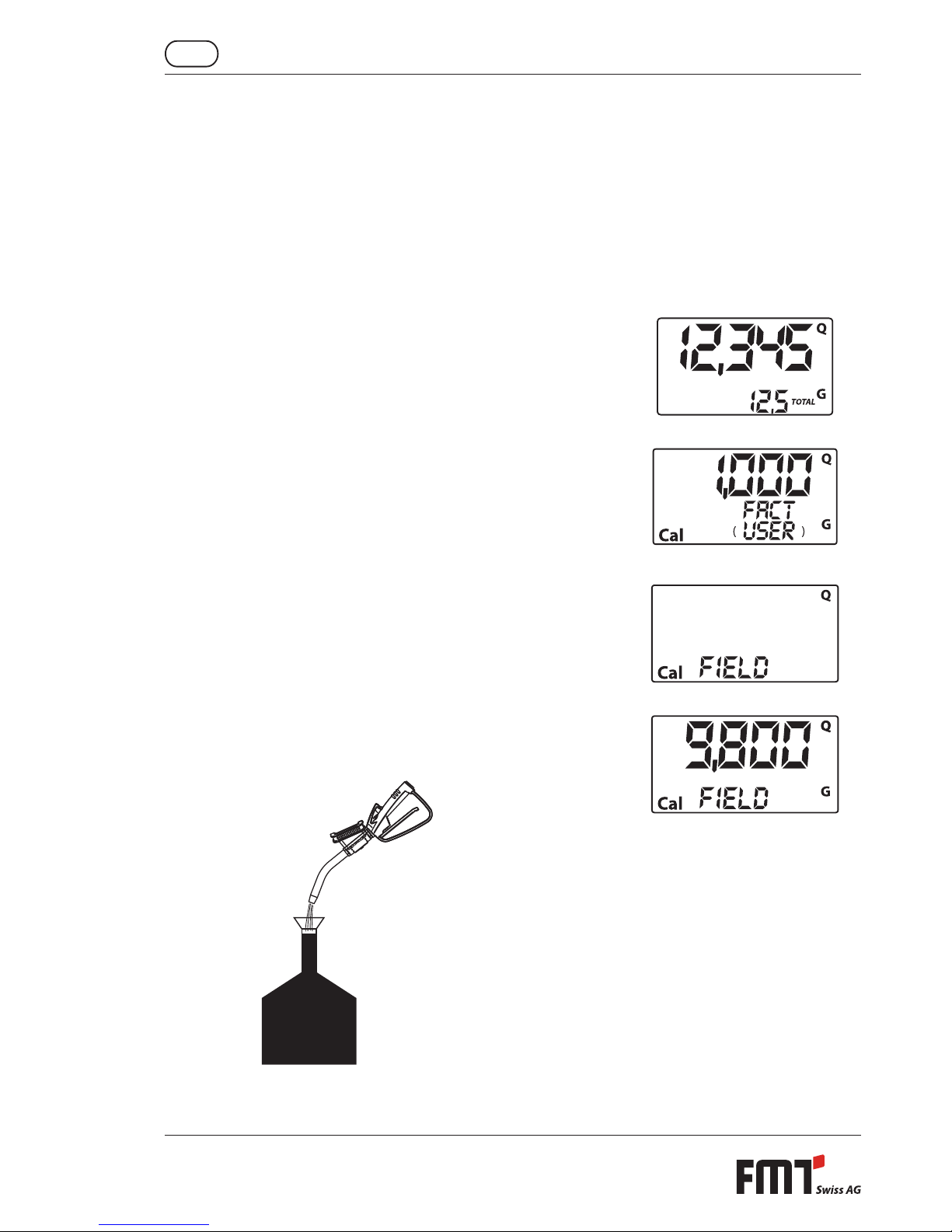
9.4.2 Calibration procedure during operation
Operation Display-Conguration
1 NONE
Counter in normal mode, not counting
2 LONG PRESS ON THE TOTAL KEY
The mobiSERVE enters into the calibration mode, shows
the message TOTAL and the calibration factor used instead
of the total amount. The messages FACT and USER indicate
which one of the two factors (manufacturer or user ) is
currently being used.
3 LONG PRESS ON THE RESET KEY
The mobiSERVE indicates the TOTAL screen and the
resettable total amount indicator is zero. The counter is
ready to carry out a calibration during operation.
4 DISCHARGE IN THE CALIBRATED CONTAINER
Start the dispense in the calibrated container without
pressing a key.
19
Operating instructions - mobiSERVE
GB
The discharge procedure can be interrupted and started
at any time. Carry out the discharge until the uid has
achieved the measuring scale of the calibrated container. It
is not necessary to achieve a certain amount.
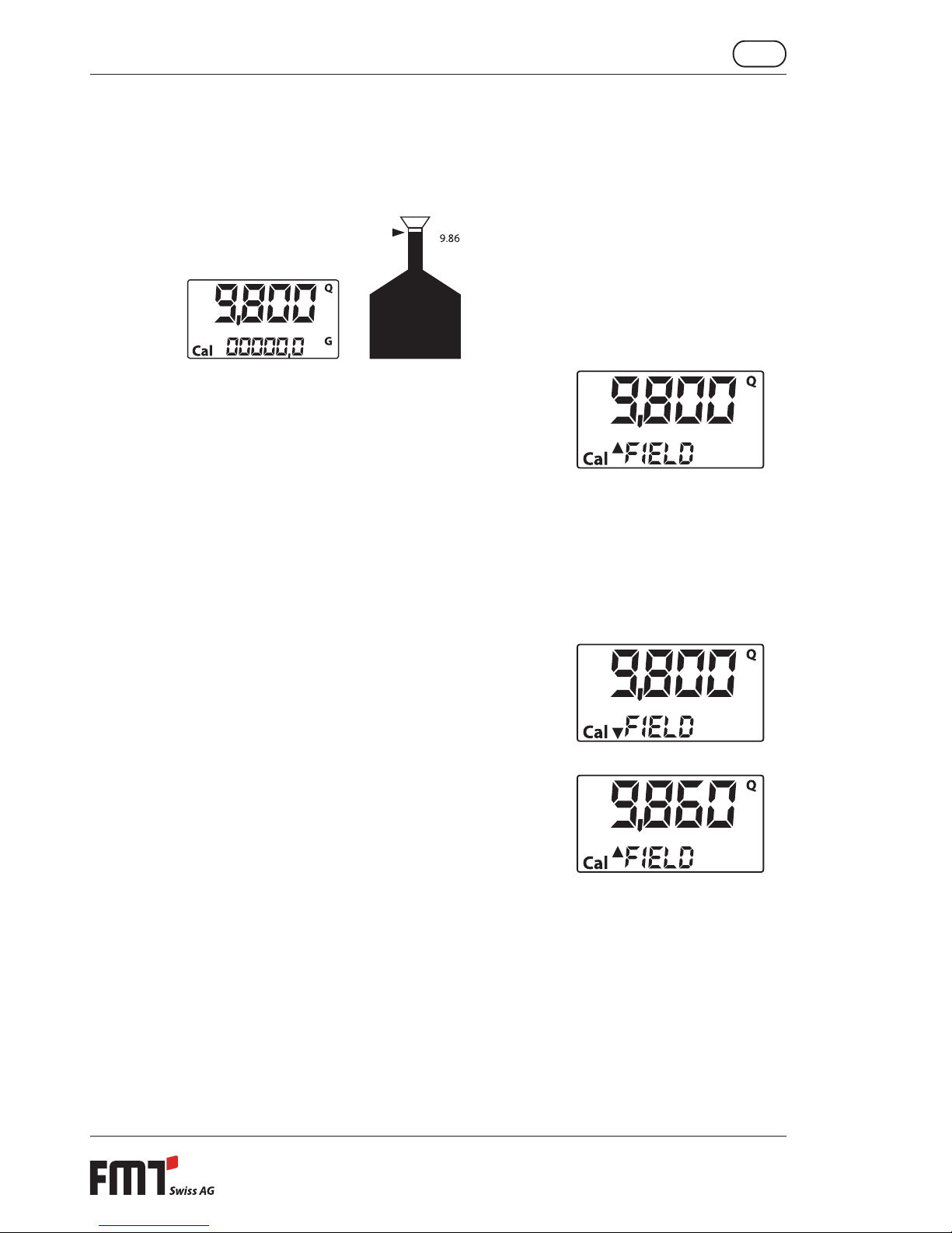
Set value Actual value
5
SHORT PRESS ON THE RESET KEY
The mobiSERVE is informed that the calibration discharge is
nished. Check to ensure that the discharge is completely
nished before this happens.
To calibrate the mobiSERVE, the value indicated by the
partial amount counter (example 9.800) must be brought
to the actual value indicated by the calibrated container.
On the lower left corner of the display, an arrow appears,
pointing upwards or downwards, thus indicating the
direction in which the USER K FACTOR value is changed.
Increase or reduce when the operations 6 or 7 are carried
out.
6 SHORT PRESS ON THE RESET KEY
Change of arrow direction. This procedure can be repeated
as often as required.
7 SHORT/LONG PRESS ON THE TOTAL KEY
The value indicated is changed in the direction dened by
the arrow:
One unit for each short press on the TOTAL key
Continuously, when the TOTAL key is kept depressed -
the rst 5 units change slowly, then quickly.
If the value desired is exceeded, repeat the operation
from point 6 (6).

20
GB Operating instructions - mobiSERVE
8 LONG PRESS ON THE RESET KEY
The mobiSERVE is informed that the calibration procedure
is nished.
Before this operation is carried out, check to ensure
that the STANDARD VALUE corresponds to the ACTUAL
VALUE.
Actual value
The mobiSERVE calculates the new USER K FACTOR. This
calculation may take some seconds, according to the
correction to be made. During this procedure, the arrow
disappears, but TOTAL remains on the screen.
If this procedure is carried out after point 5 without
changing the value indicated, the USER K FACTOR is equal
to the FACTORY K FACTOR and is thus ignored.
9 NO OPERATION
After the calculation, the new USER K FACTOR is indicated
for some seconds, then, the restart procedure is repeated in
order to nally get into the standby mode.
ATTENTION: From that moment, the value indicated is the
new calibration factor used by the counter, and it remains
so, also after a battery replacement!
10 NO OPERATION
The mobiSERVE stores the new operating calibration factor
and is prepared for discharge with the USER K FACTOR just
calculated.
9.4.3 Direct change of the K FACTOR
This procedure is especially helpful in order to correct an average error, which may occur because of the
multitude of tasks carried out. If, during normal counter operation, an average percent error occurs, this
one may be corrected by altering the calibration factor currently being used by the same percent value. In
this case, the percentage of the correction of the USER K FACTOR can be calculated by the user as follows:
new calibration factor = old calibration factor x
Table of contents
Popular Pressure Washer manuals by other brands


Pulsar
Pulsar PWG3000H owner's manual

North Star
North Star 157596 owner's manual

Villager
Villager VHW 100 Operator's manual

Generac Portable Products
Generac Portable Products 1675-0 owner's manual

North Star
North Star M157304G Installation, operation and maintenance manual

Simoniz
Simoniz SPD-220 Operator's manual


