Fokke RC MESSERSCHMITT BF-109 E4 User manual

1
INSTRUCTION
For advanced modelers
MESSERSCHMITT BF-109 E4
1:5
Technical Data:
Wingspan: 1980mm
Length: 1752mm
Weight: 9kg
Engine: 30-50cc gas engine
Electric motor-2500-3000W

2
Dear Friend,
Congratulations on your choice.
The 1/5 scale Full Kit of the famous German Messerschmitt BF 109 E is offered in a composite
format with most of the detail work already done. However we appreciate that you derive great
pleasure from building your models and so we have left some building for you to do. We hope you
enjoy this build.
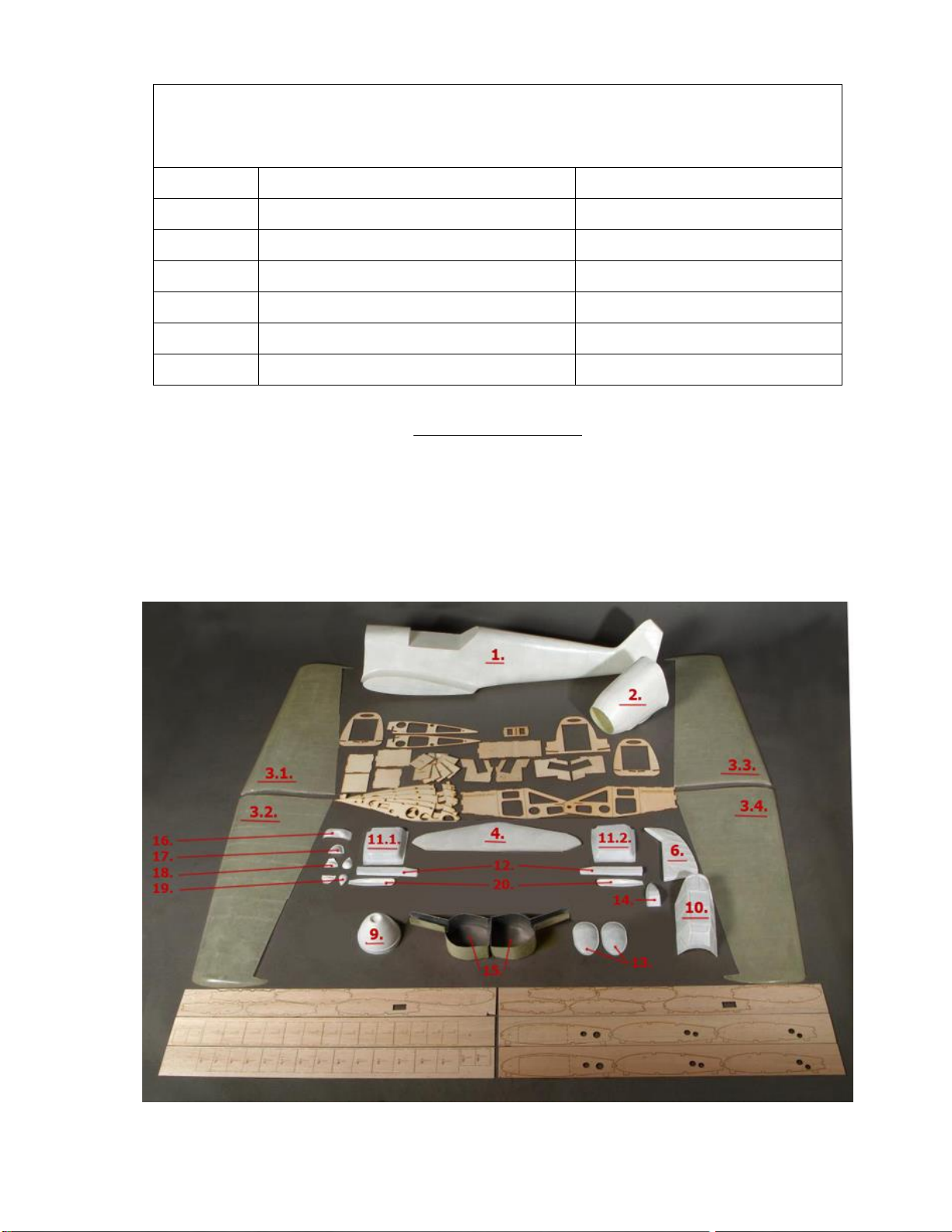
In the kit you will find:
Part No
Description
Qty.
Material
1.
fuselage
1
composite
2.
nose of fuselage
1
composite
3.
wings
2xL+2xR
composite
4.
horizontal stabilizer
1
composite
5.
elevators
L+ R
wood
6.
rudder
1
composite
7.
flaps
L+ R
wood
8.
ailerons
L+ R
wood
9.
spinner
1
composite
10.
frame of the cockpit
1
composite
11.
under wing water coolers
L+ R
composite
12.
exhaust covers
L+ R
composite
13.
gun bulges
L+ R
composite
14.
oil cooler
1
composite
15.
wing gear wheel wells
L+ R
composite
16.
nose cowl machine gun bulge
1
composite
17.
bottom intercooler
1
composite
18.
nose cowl bulges
L+ R
composite
19.
bottom bulges
L+ R
composite
20.
nose cowl machine gun troughs
L+ R
composite
LASER CUT FUSELAGE PARTS
3mm poplar plywood
T1 –T11
Fuselage wood parts
22 pcs
3
LASER CUT WING PARTS
3mm poplar plywood, 3mm balsa, 4mm balsa, pine stringers
F1 –F2
3mm plywood ribs
8 pcs
L1 –L2
3mm plywood longerone det.
8 pcs
3mm balsa 100x1000mm sheet
3 pcs
4mm balsa 100x1000mm sheet
8 pcs
5x5x850mm pine stringer
2 pcs
5x10x850mm pine stringer
6 pcs
5x10x600mm pine stringer
4 pcs
RECOMMENDATIONS
1. Engine –30-50cc 2 stroke Gas or 30- 35cc Glow or electric 2500-3000W
2. Landing Gear –Sierra, Lado, Robart over 18-25 lbs model ; 80-90° retraction angle
3. Wing Tube- aluminum or carbon fiber glass tubes Ø15mm and Ø35mm
4. Wheels –5 inches Dubro wheels
5. Cockpit, instrument panel- aerocockpit.com
6. CG is located on 25% of width of the wing or 12 sm from the leading edge. Angle of the engine is 2 degrees to the left
looking from the front of the model. Follow the drawings for details.

4
Profiles of all fuselage laser cut parts

5
Profiles of all wing laser cut parts
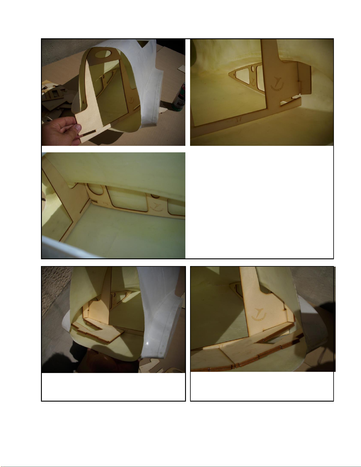
FUSELAGE ASSEMBLY
Start by epoxying the relevant pieces into the fuselage.
Note: Follow the photos to get the correct installation sequence.
Step 1
Install the Root Rib T10 into the wing root area.
Step 2
Do the same with T9 to the other side wing root.
6
Step 3
Laminate Fuselage Formers T7a & T7b together to form a 1/4
thick former. Epoxy into the Wing Root Ribs previously installed
and to the Composite Fuselage all the way round.
Step 4
Laminate Gear Plates T8a & T8b and T8a1 & T8b1 together
respectively. Install with epoxy to Fuselage Former T7a/b. Note
the orientation of the retract mounting space.
Step 5
Follow step 4 and glue in the other side Retract Plate to the
other side Fuselage Former, then glue T10a to T9a details to
T10 and T9 ribs.
7
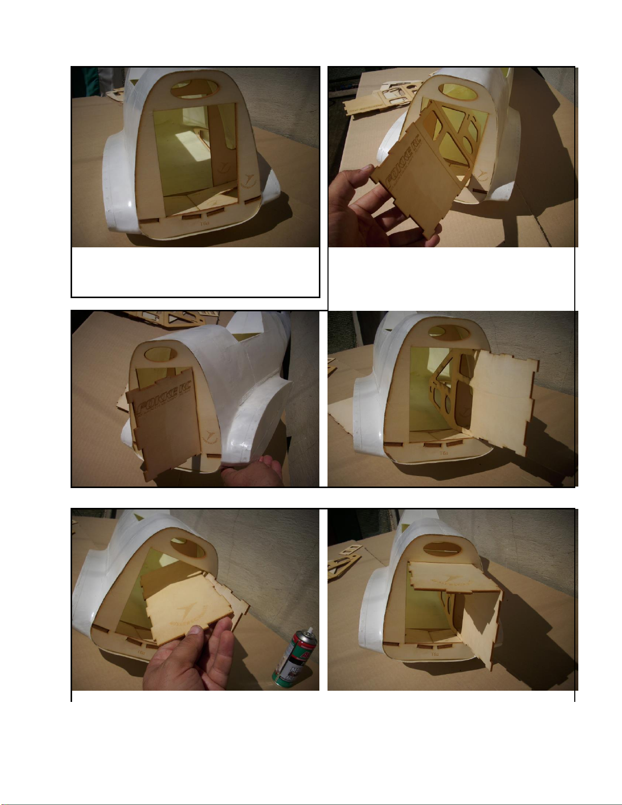
Step 6
Glue in Former T6a. Epoxy into Fuselage and to the Gear Plates
as shown.
Step 7
Install the engine box. Simple twist and turn interlocking
construction. Just follow the photos. Note the orientation of
the box sides.
8
Step 8
Part T2 goes at the top.
Step 9
….and next T5

9
Step 10
Part T3 is on the bottom of the box.
Step 11
Glue T1a, T1b and T1c together.
Step 12
Close the box with these laminated parts.

10
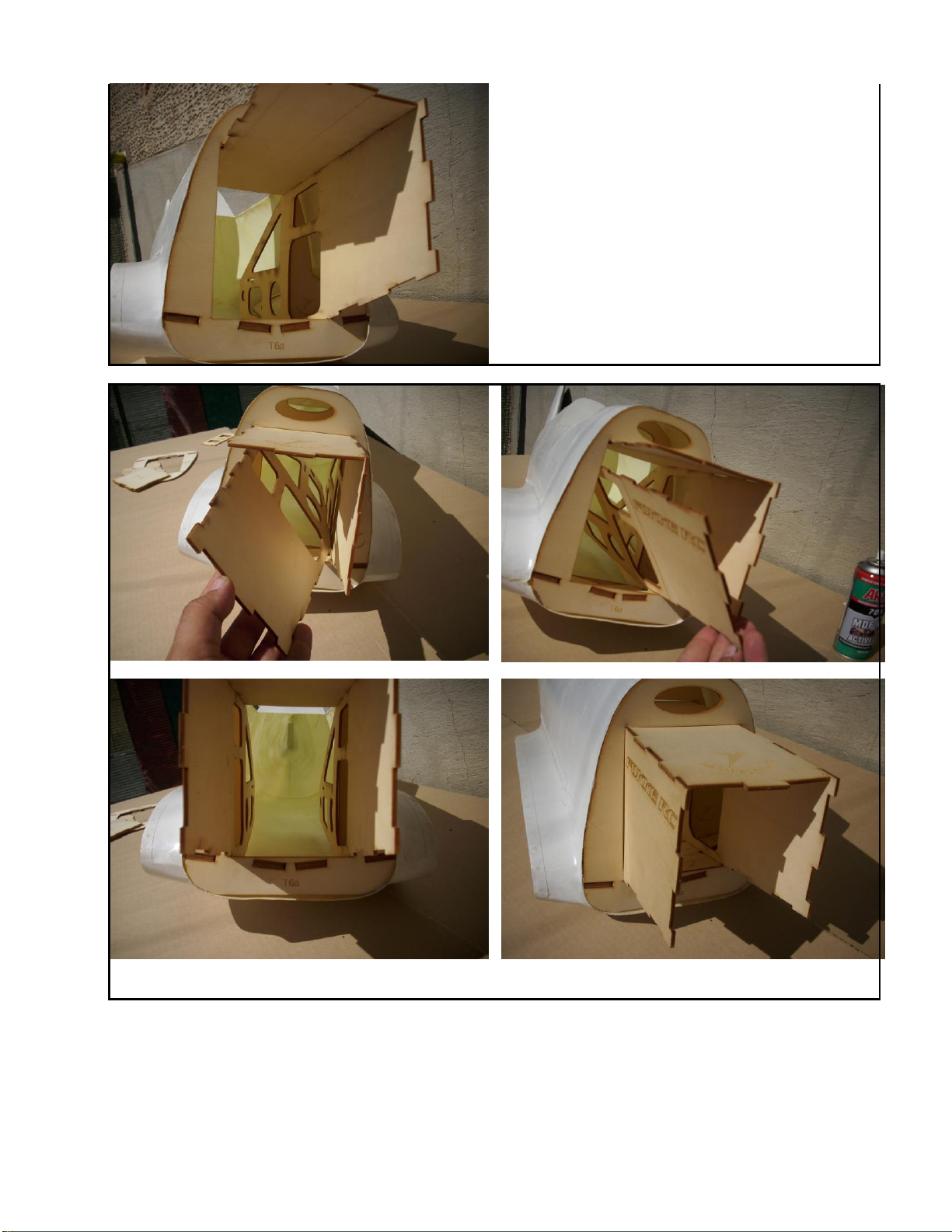
Step 13
Next is the detail T6b. When you finished the engine box we
recommend covering with glass 163gr and Epoxy Resin.
Step 14
The final step –glue the servo tray T11 in place.

11
WINGS ASSEMBLY
We recommend the use of Epoxy Resin adhesive for the wing construction. All ribs are at 90 degrees to the work surface.
Follow the drawing for spacing and angles!
Sequence is shown below:
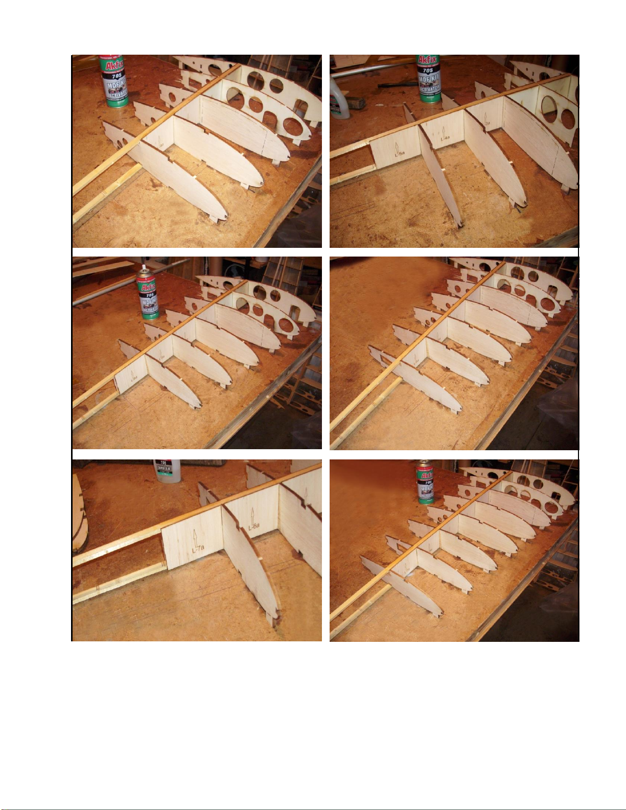
Step 1
Laminate Root Ribs F1 & F1a together. Lay down a 5x10x850mm
pine lower spar and start assembling the ribs and the spar shear
webs from the Root Rib end. Make sure the spar shear webs are
installed with the arrow pointing up and that they are installed
back to back. Install the upper 5x10x850mm pine spar at some
stage to help with assembly. Follow the dimensions and sequence
shown in drawing.

12
Step 2
Ensure that the wing tubes are at 90° to the Root Rib.
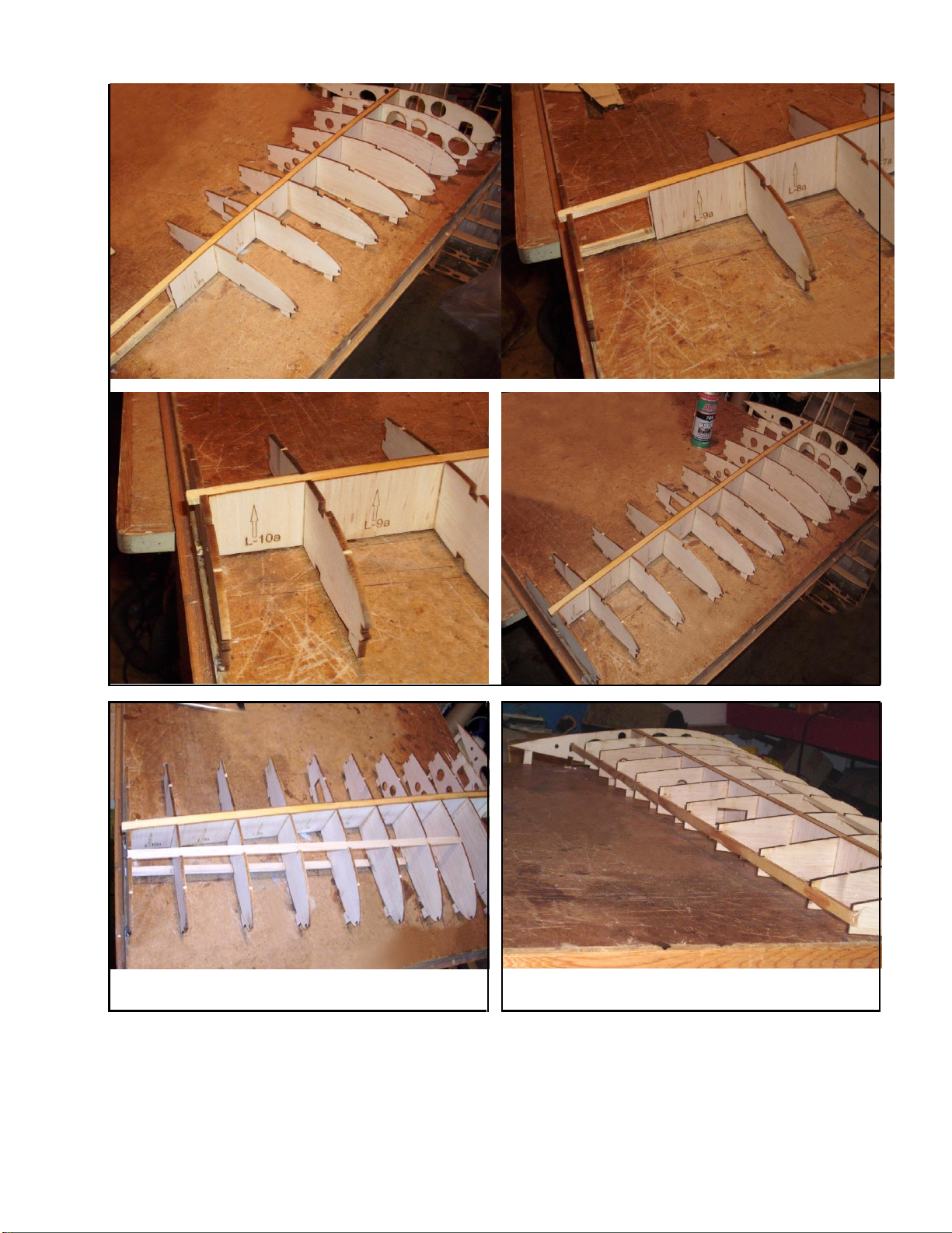
Step 3
Continue steps 1 & 2 to complete the wing structure. Follow the
photos sequence.
Parts F3 to F11 are from 4mm balsa wood.
Parts L-3 to L-10 are from 3mm balsa wood.
13
14
Step 4
Install the upper and lower 5x10x600mm pine spars.
Step 5
Install 5x10x850mm pine strip to the trailing edge of the wing.
15
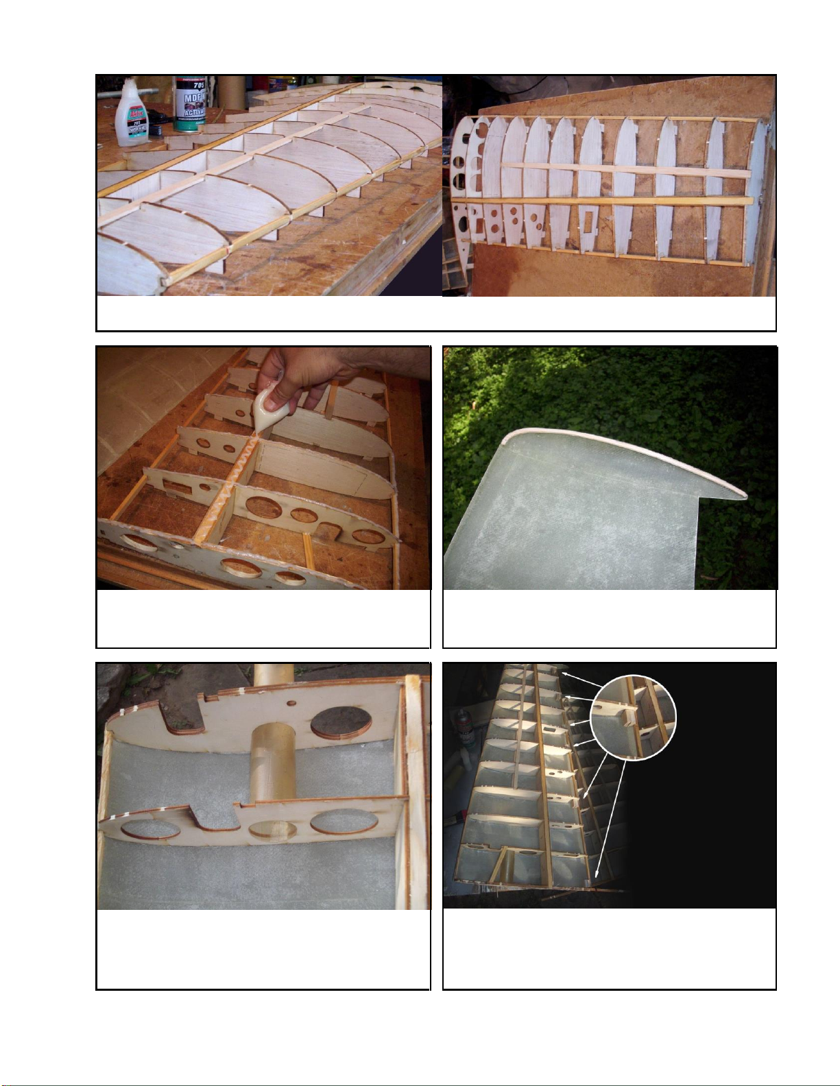
Step 6
Install 5x5x850mm pine strip to the leading edge of the wing.
Step 7
Apply Epoxy Resin adhesive to all contact surfaces with wing top
skin.
For better contact of the two wing tip skins glue balsa strip 5 x
3mm on each wing skin.
Step 8
Install the composite wing tube sleeve through the Root Rib and
Rib F2. Epoxy well.
Step 9
Install balsa wood hinge blocks 20mm thick between the upper &
lower skins at the following ribs: R1, R4, R6, R7, R9 & R10. See
photo. Also install the 5x10 pine spar from Root Rib to rib F2 at
the F1.
16
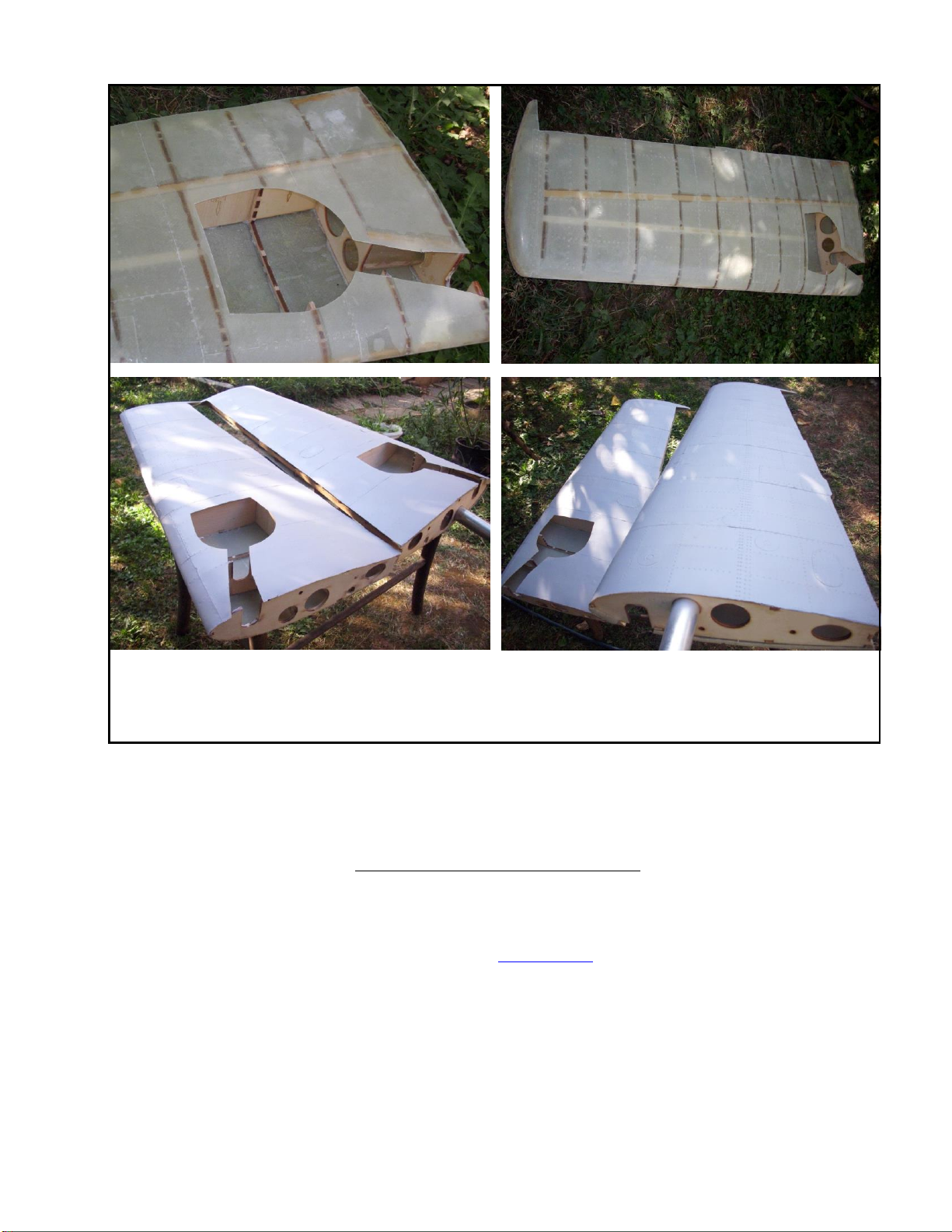
Step 10
Ensure that all of the wing structures to be glued to the composite skins have adequate glue on them. Carefully position the wing
structure into the top wing skin first then position the lower one. Tape closed any openings around the edges and weight down the
wing so as to achieve good gap-free joints inside and around the edges. After the wings are cured mark the well position and cut
out. Use information shown on the growing.
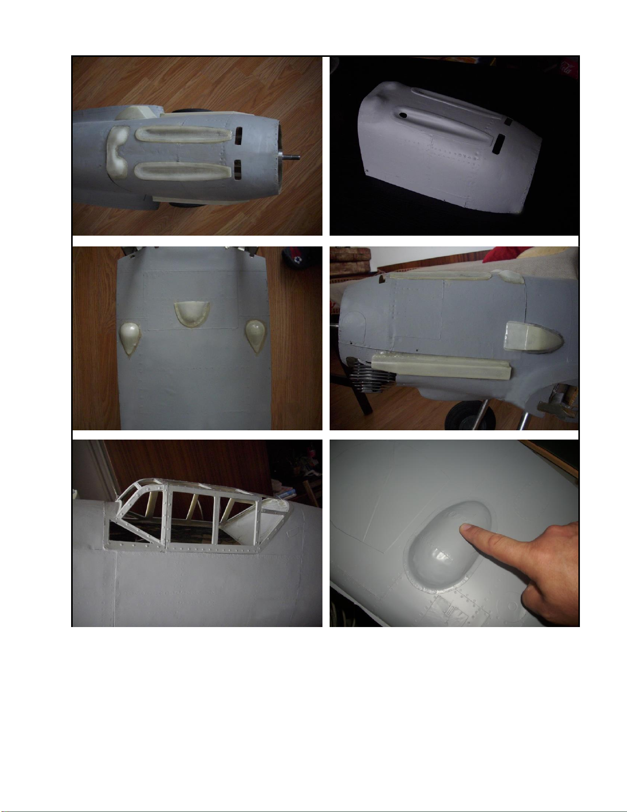
GLUE LITTLE COMPOSITE DETAILS
That’s the wing done for now. Move onto the fuselage and cowl and install the composite details.
Install the gun troughs, exhaust covers, machine gun bulge, air filter, oil cooler bulge, wing bulges.
Use the drawing for the positioning of these details.
You can use adhesive 10-min epoxy 190G arbeitspackung R&G from www.lindinger.at
17
18
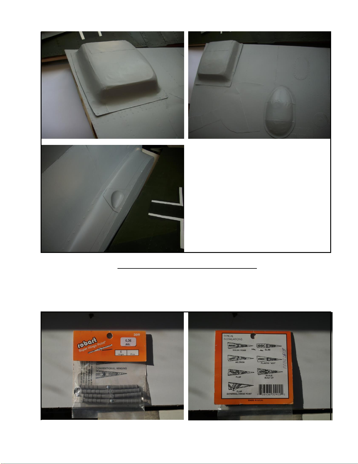
Before installing any of the composite details the surface
should be roughened up with 80 grit abrasive paper. Quick set
Epoxy or Cyanoacrylate glue.
ASSEMBLING AILERONS, FLAPS AND RUDDER
We recommend Robart hinges.
Aileron hinge installation: Mark the position of the hinges making sure they line up with the blocks glued into the wing previously. Cut
a 20mm wide gap into the ailerons leading edge. Prepare a balsa block and glue between the aileron skins leaving enough sticking out
to be sanded to match the leading edge radius. Follow the sequence shown in the photos.

19

Table of contents


