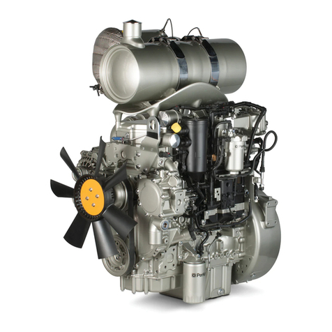
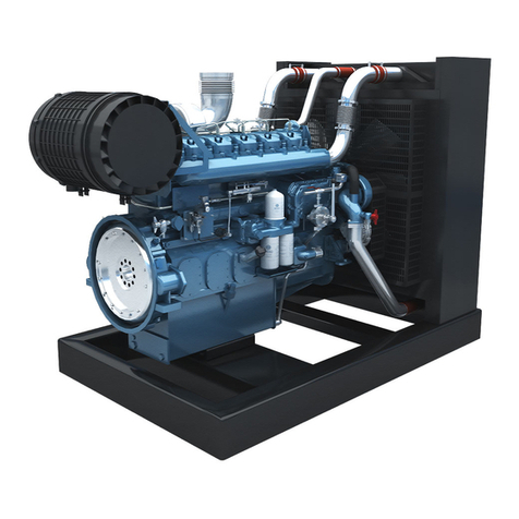
Foley Engines ZF 45 C - Walter Operating instructions

R E P A I R M A N U A L A N D S P A R E P A R T S L I S T
R E P A I R M A N U A L A N D S P A R E P A R T S L I S T
R
E
P
A
I
R
M
A
N
U
A
L
ZF 45 C version 10; 001
ZF 45 C - Walter version 002
ZF 45 C - Toyota version 11; 003
ZF 63 C version 07; 001
ZF 88 C version 001
Cod.
310.01.0056d
FOLEY ENGINES
1-800-233-6539


1
Repair Manual and Spare Parts List ZF 45C / 63C / 88C
TABLE OF CONTENTS
Introduction ........................................................... 2
SECTION I: GENERAL DATA .................................... 2
1. Transmission Set-up ....................................... 2
2. Consumable goods ......................................... 3
3. Measuring Tools .............................................. 3
4. Standard Tools and Fixture ............................. 3
SECTION II: SPECIAL TOOLS ................................. 4
SECTION III: DISASSEMBLY PREPARATION......... 5
Introduction ........................................................... 5
1. Preliminary operation ...................................... 5
2. Housing disassembly ...................................... 5
3. Input shaft ....................................................... 8
4. Forward clutch housing disassembly .............. 9
SECTION IV: ASSEMBLY .......................................... 12
Introduction ........................................................... 12
1. Input shaft ....................................................... 12
2. Housing assembly........................................... 15
3. Complementary operations............................. 18
4. Oil pump.......................................................... 21
SECTION V: PLAYADJUSTMENT ........................... 22
1. Reverse clutch clearance................................ 22
2. Forward clutch clearance................................ 23
3. Input shaft play................................................. 24
4. Output shaft bearing play................................. 25
SECTION VI: TIGHTENING TORQUES ................... 26
SECTION VII: FUNCTION TEST .............................. 26
1. Filling up with transmission fluid ..................... 26
2. Check fluid level.............................................. 26
3. Function test ................................................... 27
4. Shifting pressure ZF 45C / 63C / 88C............. 28
5. Lube oil delivery ZF 45C / 63C / 88C.............. 29
SECTION VIII: TROUBLESHOOTING...................... 30
SECTION IX: AUTOMATIC TRANSMISSION
FLUID.................................................. 33
SECTION X: SPARE PARTS LISTAND
EXPLOSION DRAWINGS.................... 35

Repair Manual and Spare Parts List ZF 45C / 63C / 88C
2
INTRODUCTION
Thismanualgivesspecificinstructionsfortheproperrepair
on ZF 45C / 63C / 88C model transmissions.
Please follow the procedures carefully to insure quality
service.
ZF HURTH MARINE recommends to read the manual
completely before starting with repairs, as some of the
procedures described are rather complex.
Along with standard tools, ZF HURTH MARINE
recommendstheuseofspecialtools,necessarytoperform
repairs correctly. The special tools are available trough
your local ZF HURTH MARINE dealer.
This manual is based on the technical information at the
timeof printing.The manualhas beenchecked carefullyin
order to avoid errors. However ZF HURTH MARINE is not
liable, for any misrepresentations, errors of description or
omissions.
Modificationsonfuturemanualsmaybeintroducedwithout
prior notice.
Thefollowinginternationalsymbolsareusedinthisservice
manual.
SECTION I: GENERAL DATA
1. TRANSMISSIONS SET-UP
The main components of the HSW Marine Transmissions
are:
Item 1two-piece aluminum die cast
1.1 oil filter
1.2 oil dipstick
1.3 pump
Item 2gears
2.1 input shaft with forward clutch
pack assembly
2.2 planet gear carrier assembly
Item 3control valve
1.2
2.2
2.1
WARNING:THISSYMBOLWARNSOFPOSSIBLE
PERSONAL INJURY.
CAUTION:Thissymbolwarnsofpossibledamage
to transmission.
1.3
3
1
1.1

3
Repair Manual and Spare Parts List ZF 45C / 63C / 88C
2. CONSUMABLE GOODS
For cleaning:
Cold cleaner such as benzine, trichloroethane or Loctite
fast cleaner No. 7063.
WARNING
Keepdetergentsawayfromyourskin,donotdrinkand
do not inhale their vapors! Always wear protective
gloves and safety glasses!
Note accident prevention rules!
For assembly:
•Loctite 245 for securing output flange on spline
•Loctite 574 on the outside diameter of the seals and on
mating surfaces
•Grease: Klüber STABURAGS NBU 30, for radial shaft
seals
•ATF Fluid - 1.75 Liters (1.85 US qts)
[see ATF fluid list chap. IX]
3. MEASURING TOOLS
Dial indicator gauge with arm-type support
Range 0 - 1" (0 - 25 mm) in 0.0005" (0.01 mm) increments
Caliper
Range0-6"(0-150mm)in0.0005"(0.01mm)increments
1/2" tool bar
working edge within 0.0002" per 12"
4. STANDARD TOOLS AND FIXTURE
Wrench
for hexagon bolts (8 mm, 13 mm, 14 mm, 17 mm, 19 mm,
22 mm)
Allen wrench
(5 mm, 6 mm, 8 mm)
Hexagon drive socket wrench
(13 mm, 17 mm, 19 mm)
Torque wrenches
Ranges:
-20 lb in -200 lb in (5 Nm - 65Nm)
-15 lb ft - 100 lb ft (30 Nm - 150 Nm)
Plastic hammer (1000 g) (24 oz)
sturdy screwdriver
- Pullers
blindholebushing (planetarygearassembly)range1/4" to
1 3/4" 4 lb slide hammer
output flange range 3 1/2" to 5 1/2" 5 ton; 3 - jaw
No. 2 Pry bars
1/2" stock
Snap ring pliers
sizes: 9" (shaft diameter 1 1/2" to 3 1/2")
10" (bore diameter 1 1/2" to 4")

Repair Manual and Spare Parts List ZF 45C / 63C / 88C
4
SECTION II: SPECIAL TOOLS
It is assumed that all standard tools, such as, torque
wrenches,open-endwrenches,AllenKeysandextractors,
are available.
All fixtures for pressing in and out should be used in
conjunctionwithahydraulicormanualpress.Identnumbers
are also stock reference numbers.
Mandrel
Oil pump seal, (Id. No. 500493)
P/N 978.45.0022.0
Mandrel
Bushing, (Id. No. 500494)
P/N 978.45.0023.0
Mandrel
Control valve oil seal, (Id. No. 500495)
P/N 978.45.0024.0
Mandrel
Input shaft rollers bearing, (Id. No. 500496)
P/N 978.45.0025.0
Mandrel
Forward clutch circlip, (Id. No. 500497)
P/N 978.45.0026.0
Mandrel
Input shaft ball bearing (Id. No. 500498)
P/N 978.45.0027.0
Mandrel
Output shaft ball bearing, (Id. No. 500499)
P/N 978.45.0028.0
Plate
Housing support, (Id. No. 500500)
P/N 978.45.0029.0
Plug
Forward clutch, (Id. No. 500501)
P/N 978.45.0030.0
Wrench
Output flange, (Id. No. 500446)
P/N 978.40.0002.0
Antirotation bracket
Output flange, (Id. No. 500502)
P/N 978.45.0031.0
Clamp ring
Input shaft play, (Id. No. 618582)
P/N 219.354.3

5
Repair Manual and Spare Parts List ZF 45C / 63C / 88C
2. HOUSING DISASSEMBLY
2.1 Position the marine gearbox on the housing support
(P.N. 500500).
2.2 Screw off bolts (6) and washers (10). Remove the
pumpcoverassembly(34).Inspectsealingring(1)and
O-Ring(33);inspectforwearandreplaceifnecessary.
2.3 Removetherotorpumpfromtheshaft.Ifitneedstobe
replaced, the complete cover assembly (34) has to be
replaced.
NOTE:Pumpgearshould beinstalledthesamesidedown
as removed.
SECTION III: DISASSEMBLY
PREPARATION
INTRODUCTION
Clean the transmission thoroughly on the outside before
disassembly.
The repair area should be clean and well lighted.
ZF HURTH MARINE recommends using a stand (P.N.
500500) for aiding in assembly and disassembly.
1. PRELIMINARY OPERATION
1.1 Remove the breather valve (22) and oil dipstick (26).
Clean the breather with suitable cleaner, allow to dry
and coat with oil.
1.2 Screw off bolts (6) and washers (10), remove the filter
cover(5),seal(4)andfilterelement(3).Inspectsealfor
wearandreplaceifnecessary.Cleanthefilterelement
with suitable cleaner.
WARNING
Position a container to pick up the oil flow.

Repair Manual and Spare Parts List ZF 45C / 63C / 88C
6
2.7 Remove the cover (35).
2.8 Remove reverse clutch first outer disc (63).
2.9 Remove springs (58).
2.4 Using pliers remove the key (28) from shaft.
NOTE: Take note of the position of the key.
2.5 Screw off bolts (7), (8) and washers (10).
2.6 Bytappingwithasofthammerseparatethecover(35)
from the housing (36).

7
Repair Manual and Spare Parts List ZF 45C / 63C / 88C
2.13 Turn the housing upside down. Using the tool
P.N.500446 loosen nut (72); stop the output flange
(66) from turning using tool P.N.500502. Discard O-
Ring (71) and replace with a new one.
2.14 Remove flange using appropriate puller.
WARNING
[see type page 3].
2.15 With a soft hammer disassemble the output shaft.
Driving it out from the housing.
2.10 Remove inner disc (62), outer disc (63), inner disc
(62), the last outer disc (63) and if present shims
(64),(65).
2.11 Pull out the shaft and forward clutch assembly.
2.12 Removethrust washer(45)which isremainedon the
planetgearcarrierassemblyand(withstandardpuller)
bushing (46).

Repair Manual and Spare Parts List ZF 45C / 63C / 88C
8
3.3 With pliers remove the circlip (44).
NOTE: Take note of the position of the circlip (44).
3.4 Supportthe ringgear allowingroomfor theinput shaft
with gears to come out bottom side.
NOTE: Pressing on splined end of shaft disassemble it
from the clutch housing.
This operation will damage the bearing.
Use a press with:
distance: 200 mm (8 inches)
min. force: 2000 kg (4400 lbs)
3.5 Remove piston rings (40) from the input shaft (37).
3. INPUT SHAFT
3.1 Remove piston rings (39) from the input shaft (37).
3.2 Remove spacer (42b), needle bearing (42a), other
spacer (42b) and shims (75-76).
2.16 Don't disassemble the output shaft.
If it's necessary to replace it, ask for complete gear
carrier assembly (38).

9
Repair Manual and Spare Parts List ZF 45C / 63C / 88C
4.4 Remove forward clutch inner (60), outer (61) shims
(73) (74) and end disc (59).
WARNING
4.5 Remove circlip (55), cup springs (54).
Remove only if defective.
4.6 WithatoolP.N.500498driveoutballbearing(43)which
has to be discarded and replaced with a new one.
4.7 Introduce air with tool P.N. 500501 to push out the
piston (51).
The piston can also be removed by gently tapping on
the outer diameter of the housing with a soft hammer.
4. FORWARD CLUTCH HOUSING
DISASSEMBLY
4.1 Remove circlip (48).
WARNING
4.2 With a screwdriver remove the circlip (50).
4.3 Support clutch housing flat on to a work bench. Sepa-
rate ring gear support (47) from the ring gear (49).
51
500501 47

Repair Manual and Spare Parts List ZF 45C / 63C / 88C
10
4.8 Remove O-Rings (52), (53) from the piston (51).
WARNING
4.9 Inject air through the indicated hole, to remove the
piston (56). The hole is located on the upper circular
surface of the housing cover (clutch piston side) just
under the piston screw (18).
4.10 Remove the O-Ring (33) from cover (35).
4.11 Remove O-Rings (57) from piston (56).
NOTE: Replace O-Rings (33, 57) if disassembled.
4.12 Removethe stopscrew(17) andpositionscrew (18),
thetwowashers(13),thespring(20)andtheball(21).
4.13 Removethe neutralsafetyswitch (15),theplugs (12,
14), spacer (16), ball (21) and washer (19).
4.14 Using two screwdrivers pull out the distributor shaft
(24), the distributor shaft seal (23) will come out
together.
Remove seal ring (23) from the spool valve (24).
NOTE: 1 - Take note of the position of the seal ring.
2 - Replaced the seal ring if disassembled.
CAUTION
Don't disassemble the distributor shaft (24), if it's
necessary to replace it use the complete group.
13
17
13
18

11
Repair Manual and Spare Parts List ZF 45C / 63C / 88C
4.17 Remove baffle (29).
With a screwdriver take out an end of the baffle from
the groove on the housing.
Bygrippingandrollingupthebaffletakeitoutfromthe
housing.
NOTE: ZF 45C VERS. TOYOTA 11 ONLY
Twoadditionalbaffles(30)and(31)andpinspacer(32)are
present.
4.18 Remove output sealing ring (2).
NOTE: This operation will damage the oil seal.
4.19 Remove circlip (70).
4.15 Bystrikingwithasofthammerremoveneedlebearing(41).
Only if bearing is defective.
To do it properly support the cover allowing room for the
needle bearing to come out bottom side. Stick a screw
driver/punch into the internal edge of the cage and tap
gently with a soft hammer in a criss cross pattern.
NOTE: This operation will damage the bearing.
WARNING
The improper useof screwdriver/punchcandamage
the cover. After having removed the bearing check for
scratches on the cover.
4.16 Remove sealing ring (1) and O-Ring (33) from pump
cover (34).
NOTE: This operation will damage the sealing ring.
Take note of the position of the seal ring.

Repair Manual and Spare Parts List ZF 45C / 63C / 88C
12
1. INPUT SHAFT
1.1 InstallO-Rings (52)(53) on thepiston (51).Insertthe
piston into the input bell (47).
NOTE: Wet the O-Rings with ATF.
Wet the mating surfaces with ATF.
Complete the assembly with a soft hammer.
WARNING
1.2 Position cup springs (54) as shown in figure.
First cup spring has to be installed with the bigger
diameter against the piston.
Second and third cup springs have to be installed in
succession with their bigger diameters against each
other.
SECTION IV: ASSEMBLY
INTRODUCTION
Awell-lightedworkareathat isfreefromdirtandchips,will
facilitate the work considerably.
ZF HURTH MARINE recommends to use a swivelling
stand, described in the disassembly section to aid in the
assembly.
Thoroughly clean all mating surfaces from any loctite or
gasket material.
WARNING
Cleanersandsolventscanbetoxicandharmfulwithout
proper ventilation.
Use caution when using such cleaners.
Always wear protective gloves and glasses!
The next assembly procedure requires the following:
•A hydraulic or mechanical press.
4.20 Supporthousing(36)flatonapress,pressoutbearing
(67), then remove shims (68) (69).
NOTE: This operation will damage the bearing.
51 54
35
Tool
36
67

13
Repair Manual and Spare Parts List ZF 45C / 63C / 88C
1.6 Insertenddisc(finishedsideup)(59), shims(73 -74)
and alternatively outer clutch disc (61) and inner
clutch disc (60).
NOTE: To set correct play see item 2 page 23.
Clutch discs have to be coated with ATF.
1.7 Withtoolp.n.500498andasuitablesupportpressthe
ball bearing (43) into the ring gear support (47).
1.8 Insert the circlip (48).
WARNING
Besurethatsnapringhasbeenproperlyseated(check
circlipopeningtobenotclosetoslotsinclutchhousing).
1.3 Position the circlip (55).
1.4 With tool P.N. 500497 compress the cup springs.
Be sure of their aligment.
1.5 Install the piston rings (40).
NOTE: Coat sealing rings with grease or Petroleum Jally.

Repair Manual and Spare Parts List ZF 45C / 63C / 88C
14
1.12 Install the circlip (50).
WARNING
Be sure that snap ring has been properly seated (check
circlip opening to be not close to slots in clutch housing).
1.13 Install onto input shaft (37) the seal rings (39).
NOTE: Install seal rings (39) with openings in opposite
positions.
1.14 Insert shims (75, 76) between circlip (48) and thrust
washer (42).
NOTE: To set correct play see item 3 pag. 24.
1.9
Presstheforwardclutchhousing(47)on the inputshaft
(37).
1.10 Install the circlip (44).
NOTE: Check carefully correct position of the circlip (44).
1.11 Turn up side down the ring gear (49) and place it on
a suitable support, allowing the shaft go down
completely.
Insert the input shaft (37) into the ring gear (49)
allowingtheinnerclutchdiscstobedrivenbythedisc
carrier.

15
Repair Manual and Spare Parts List ZF 45C / 63C / 88C
2.2 Insert the baffle (29) as shown in the picture. The fold
of the baffle must correspond with the groove on the
housingoppositetothebreatherpositiononthesecond
foldintothesame slot.Thebafflemustbestraightand
tight up against the under side of the housing.
NOTE: ZF 45C vers. TOYOTA 11 only
Install additional baffles (30, 31) and pin spacer (32).
2.3 With special tool P.N. 500496 install needle bearing
(41) into the cover (35).
2.4 Install O-Rings (33) into the cover (35).
1.15 WithtollP.N.500499andasuitablesupportpressball
bearing (67).
Add shims (68, 69) max bearing play:
0,1 mm (0.0039 in)
NOTE: To set correct play see item 4 page 25.
1.16 Install snap ring (70).
2. HOUSING ASSEMBLY
2.1 With tool P.N. 500499 install sealing ring (2).
NOTE:
- Use Loctite P.N. 574 between housing and sealing ring.
- Fillinternallipsofsealingringwithhighqualitygrease(for
ex. Klüber STABURAGS NBU 30).

Repair Manual and Spare Parts List ZF 45C / 63C / 88C
16
2.8 Assemble the cover (5).
Tightsbolts(6)withwasher(10).Tighteningtorque:18
Nm (13.3 lb ft.).
2.9 Installspoolvalve(24)ontofrontcover(35)chekingfor
the correct alignement of groove.
2.10 Install stop screw (17) with washer (13) Tightening
torque: 12 Nm (8.9 lb ft.).
Installontocover(35)ball(21),spring(20)andguide
spring (18) together with sealing washer (13).
Guidespring(18)tighteningtorque:12Nm(8.9lbft.).
Turn slowly spool valve (24) to centre groove to ball
(21).
NOTE:Theplugshowninthefigurewiththearrow,willonly
be tighten if the distributor is correctly oriented.
2.5 Install O-Ring (57) into the piston (56).
Wet O-Ring with ATF oil and using a plastic hammer,
install the assembled piston (56) into cover (35).
2.6 Install the filter (3).
2.7 Install the rubber oil plate (4).

17
Repair Manual and Spare Parts List ZF 45C / 63C / 88C
2.14 Install plug (14) and washer (19).
NOTE: Tighten to 25 Nm (18.5 lb ft.) torque.
2.15 Install sealing ring (23) using the special tool P.N.
500495 and a plastic hammer.
NOTE: Check the correct position of sealing ring (23).
2.16 Install the lever (25) with bolt (11) washer (10) and
nut (9).
NOTE: Tigthen bolt (11) to 22.5 Nm. (16.5 lb ft.) torque.
2.11 Installbushing(16)inthewaythatitsbiggerdiameter
is up.
2.12 Install the ball (21).
2.13 Install the microswitch (15).

Repair Manual and Spare Parts List ZF 45C / 63C / 88C
18
3.3 Install the thrust washer (45).
CAUTION
Be sure the bend correspond with the hole.
3.4 Assemble the input shaft assembly into the housing.
NOTE: To set correct play see item 3 page 23.
3. COMPLEMENTARY OPERATIONS
3.1 Install the friction bearing (46) with tool P.N. 500494.
3.2 Assemble the output shaft by pressing the shaft into
the housing.
NOTE: Coat output shaft with grease prior to assembly.
As a precaution support the inner race of the bearing.
Neutral Safety Switch Function check
Connect neutral safety switch with a lamp in series to a
battery. The neutral safety switch operates when the lamp
is lighted.
NOTE: The lamp must be extinguised when the pin is
pushed in.
45
Battery 14 V DC
Battery 14 V DC
Lamp 8.4 A
Lamp 8.4 A
Neutral
position
A or B
position
This manual suits for next models
3
Table of contents
