manuals.online logo
Brands
  1. Home
  2. •
  3. Brands
  4. •
  5. Fonderie SIME
  6. •
  7. Boiler
  8. •
  9. Fonderie SIME LOGO 22 OF User manual

Fonderie SIME LOGO 22 OF User manual

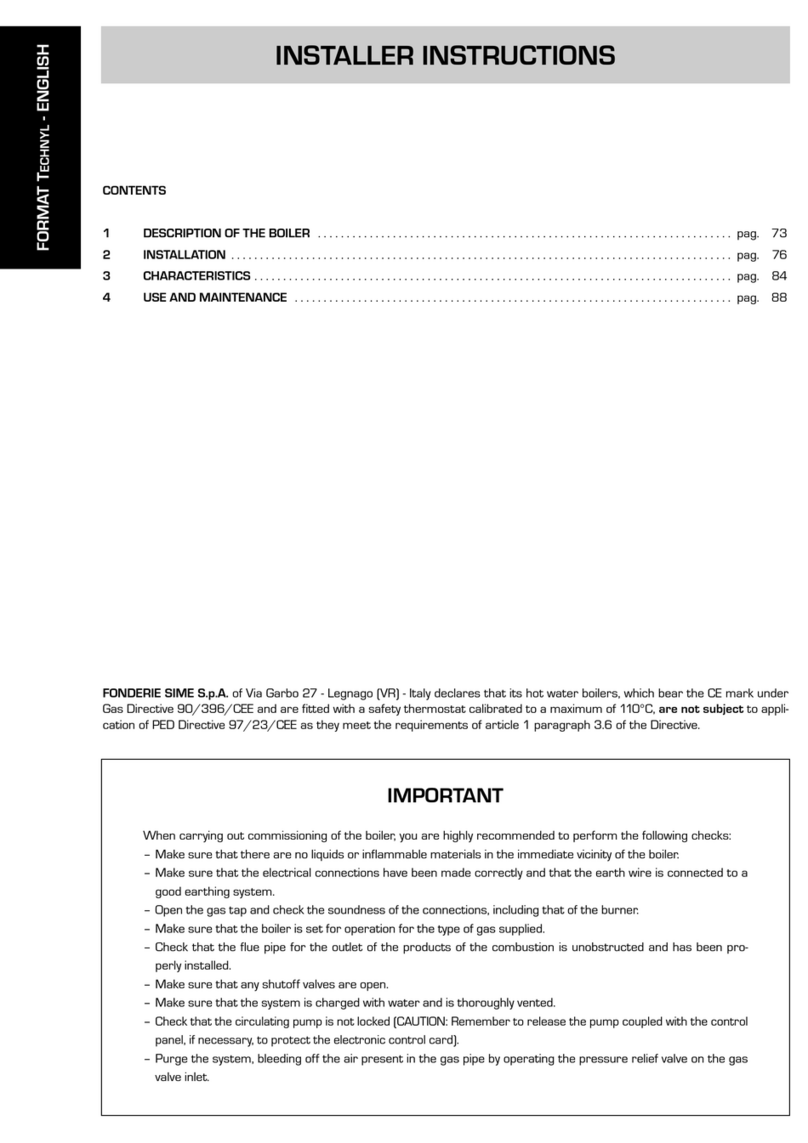
CONTENTS
1 DESCRIPTION OF THE BOILER . . . . . . . . . . . . . . . . . . . . . . . . . . . . . . . . . . . . . . . . . . . . . . . . . . . . . . . . . . . . . . . . . . . . . . . . pag. 89
2 INSTALLATION . . . . . . . . . . . . . . . . . . . . . . . . . . . . . . . . . . . . . . . . . . . . . . . . . . . . . . . . . . . . . . . . . . . . . . . . . . . . . . . . . . . . . . . pag. 94
3 CHARACTERISTICS . . . . . . . . . . . . . . . . . . . . . . . . . . . . . . . . . . . . . . . . . . . . . . . . . . . . . . . . . . . . . . . . . . . . . . . . . . . . . . . . . . . pag. 101
4 USE AND MAINTENANCE . . . . . . . . . . . . . . . . . . . . . . . . . . . . . . . . . . . . . . . . . . . . . . . . . . . . . . . . . . . . . . . . . . . . . . . . . . . . pag. 104
INSTALLER INSTRUCTIONS
IMPORTANT
When carrying out commissioning of the boiler, you are highly recommended to perform the following checks:
Make sure that there are no liquids or inflammable materials in the immediate vicinity of the boiler.
Make sure that the electrical connections have been made correctly and that the earth wire is connected to a
good earthing system.
Open the gas tap and check the soundness of the connections, including that of the burner.
Make sure that the boiler is set for operation for the type of gas supplied.
Check that the flue pipe for the outlet of the products of the combustion is unobstructed.
Make sure that any shutoff valves are open.
Make sure that the system is charged with water and is thoroughly vented.
Check that the circulating pump is not locked.
Purge the system, bleeding off the air present in the gas pipe by operating the pressure relief valve on the gas
valve inlet.
LOGO - ENGLISH
FONDERIE SIME S.p.A. of Via Garbo 27 - Legnago (VR) - Italy declares that its hot water boilers, which bear the CE mark under
Gas Directive 90/396/CEE and are fitted with a safety thermostat calibrated to a maximum of 110°C, are no subjec to appli-
cation of PED Directive 97/23/CEE as they meet the requirements of article 1 paragraph 3.6 of the Directive.
55 55
ø 130
M
RC1
S1
G
475
545
505
P460
850
Fig. 1
1.1 INTRODUCTION
“LOGO” is he hermal group wi h mul i-
gas burner wi h low of Nox premix, desi-
gned and manufactured to comply with the
european directives 90/396/CE,
89/336/CEE, 73/23/CEE, 92/42/CEE
and with the european specifications EN
297 - EN 625. This booklet provides the
instructions for the following boiler models:
“LOGO 22 OF - 32 OF”
central heating only, electronic ignition
and modulation, natural draught, mat-
chable with
“BT130 - BT150”
D.H.W.
tanks.
“LOGO 32/50 OF - 32/80 OF”
central heating and D.H.W. production,
electronic ignition and modulation, natu-
ral draught.
Follow the instructions given in this manual
for the correct installation and perfect
functioning of the apparatus.
89
1 DESCRIPTION OF THE BOILER
1.2 DIMENSIONS
M2
850
595600
1060
U
C
R3
E
345
185
105
565
710
Fig. 1/a
“LOGO 22 OF - 32 OF” version
“LOGO 22/32 OF - ank uni BT130” version
CONNECTIONS
M C.H. flow 1” M
R C.H. return 1” M
G Gas connection 3/4” M
C1 C.H. filling 1/2” F
S1 Safety valve drain 1/2” F
P mm
22 0F 615
32 0F 715
CONNECTIONS
M2 D.H.W. flow 1” M
R3 D.H.W. return 1” M
C Re-circulation 1/2” M
E D.H.W. inlet 1/2” M
Boiler drain 1/2” F
U D.H.W. outlet 1/2” M
90
700
850
840 10 5 75 75 65 65
EUMRG
S2 C S1
ø 130
797
Fig. 1/c
“LOGO 32/50 OF” version
E
640
1490
660 220
980
300
110
490
U
R3 M2
C
220
Fig. 1/b
“LOGO 22/32 OF - ank uni BT150” version
CONNECTIONS
M C.H. flow 3/4” M
R C.H. return 3/4” M
E D.H.W. inlet 1/2” M
G Gas connection 3/4” M
U D.H.W. outlet 1/2” M
C Re-circulation 1/2” F
S1 Safety valve drain 1/2” F
S2 D.H.W. tank safety valve drain 1/2” F
CONNECTIONS
M2 D.H.W. flow 1” F
R3 D.H.W. return 1” F
C Re-circulation 3/4” M
E D.H.W. inlet 3/4” M
Boiler drain 1/2” F
U D.H.W. outlet 3/4” M
91
G
460 860 45 ø130
1290
955 70 70
M
RS1
230 230
S2
70
E
230
390
C
U
Fig. 1/d
“LOGO 32/80 OF” version
Fig. 2
1.3 FUNCTIONAL DIAGRAM
KEY
1 Smoke chamber
2 Smoke stat capillary
3 Safety valve
4 Boiler expansion vessel
5 Boiler block
6 Gas pressure switch
7 Air vent valve
8 Manual air vent
9 D.H.W. circulating pump
10 C.H. circulating pump
11 Gas valve
12 Burners
13 Non return valve
14 Burners manifold
15 Water pressure transducer
16 Boiler drain cock
17 D.H.W. expansion vessel
18 D.H.W. safety valve
19 Manual filling group
20 D.H.W. tank
21 Magnesium anode
22 D.H.W. drain cock
CONNECTIONS
M C.H. flow 3/4” M
R C.H. return 3/4” M
E D.H.W. inlet 3/4” F
G Gas connection 3/4” M
U D.H.W. outlet 3/4” F
C Re-circulation 3/4” F
S1 Safety valve drain 1/2”F
S2 D.H.W. tank safety valve drain 1/2” F
92
1.4 TECHNICAL FEATURES
* When the “BT130 - BT150” tank units is connected to the boiler with the kit provided and the optional D.H.W. expansion vessel.
** Flow calculated with a fixed temperature on the D.H.W. potentiometer of 60°C for a maximum period of 10 minutes.
*** The gas flow refers to the inferior calorific value in standard conditions of 15°C - 1013 mbar
Hea ing only Combined D.H.W. ank
22 OF 32 OF 32/50 OF 32/80 OF BT130 BT150
Hea ou pu
Nominal kW 17,8÷23,7 24,1÷31,6 24,1÷31,6 24,1÷31,6
kcal/h 15.300÷20.400 20.700÷27.200 20.700÷27.200 20.700÷27.200
Minimal kW 17,8 24,1 24,1 24,1
kcal/h 15.300 20.700 20.700 20.700
Hea inpu
Nominal kW 19,5÷26,0 26,1÷34,8 26,1÷34,8 26,1÷34,8
Minimal kW 19,5 26,1 26,1 26,1
Sec ions n° 4 5 5 5
Expansion vessel
Capacity/Pre-loading pressure l/bar 8/1 10/1 10/1 10/1
Absorbed power consump ion W 105 125 125 125
Maximum wa er head bar 4 4 4 4
Maximum empera ure °C 85 85 85 85
Wa er con en l14161818
C.H. se ing range °C 40÷80 40÷80 40÷80 40÷80
D.H.W. se ing range °C 10÷60* 10÷60* 10÷60 10÷60
Ca egory II2H3P II2H3P II2H3P II2H3P
Type B11BS B11BS B11BS B11BS
Smokes empera ure ° C 108 110 116 119
Smokes flow gr/s 18,5 23,2 23,0 23,0
CO a 0% of O2 min./max (G20) ppm 10/4 10/8 7/8 10/6
CO a 0% of O2 min./max (G31) ppm 5/10 7/6 7/7 7/6
NOx a 0% of O2 average value (G20) pp m 13 13 13 13
NOx class 55 55
D.H.W produc ion
Tank capacity l 50 80 130 150
D.H.W. flow rate (EN 625)** l/min 16,2 17,3 23,5 28,9
Continuous D.H.W. flow rate ∆t 30°C
l/h 810 726 900 918
D.H.W expansion vessel l 4* 4* 2,5 4
D.H.W. maximum water head bar 7* 7* 7 7
Recovery time from 25 to 55°C min 5’ 9’ 30” 10’ 15’
Main gas nozzles
Quantity n° 3 3 3 3
Methane (G20) ø mm 2,40 2,75 2,75 2,75
Propane (G31) ø mm 1,55 N 1,80 1,80 1,80
Pilo nozzles
Methane (G20) ø mm 0,45 0,45 0,45 0,45
Propane (G31) ø mm 0,25 0,25 0,25 0,25
Gas flow***
Methane (G20) m3st/h 2,75 3,68 3,68 3,68
Propane (G31) kg/h 1,97 2,64 2,64 2,64
Gas burner pressure
Methane (G20) mbar 7,3÷12,7 7,3÷12,7 7,3÷12,7 7,3÷12,7
Propane (G31) mbar
16,6÷28,4 16,6÷28,4
16,6÷28,4 16,6÷28,4
Gas flow pressure
Methane (G20) mbar 20 20 20 20
Propane (G31) mbar 37 37 37 37
Weigh kg 139 170 225 238 89 117
1
2
3
4
5
6
7
8
9
93
2
1
3
1
4
5
6
7
8
9
10
11
12
13
14
15
1.5 MAIN COMPONENTS
Fig. 3/a
Fig. 3
“LOGO 22 OF - 32 OF” version
“LOGO 32/50 OF” version
KEY
1 Non return valve
2 Control panel
3 D.H.W. circulating pump
4 D.H.W. expansion vessel
5 Manual filling group
6 D.H.W. tank
7 D.H.W. tank drain cock
8 Boiler drain cock
9 Burners manifold
10 Pilot burner
11 C.H. circulating pump
12 Gas valve
13 Gas pressure switch
14 Safety valve
15 Ignition transformer
KEY
1 Control panel
2 Pressure transducer
3 C.H. circulating pump
4 Boiler drain cock
5 Burners manifold
6 Pilot burner
7 Gas valve
8 Gas pressure switch
9 Ignition transformer
The boiler must be installed in a fixed loca-
tion and only by specialized and qualified
firms in compliance with all instructions
contained in this manual.
Furthermore, the installation must be in
accordance with current standards and
regulations.
2.1 BOILER ROOM
AND VENTILATION
The “LOGO” version boilers with less than
35 kW power can be installed in domestic
environments when simply replacing or in a
plant room complying with current stan-
dards In rooms where open chamber gas
appliances are installed, it is important that
at least as much air at least as much air
can arrive as required by normal combu-
stion of the gas consumed by the various
appliances.
The minimum distance between the boiler
and inflammable materials has to be ≥200
mm.
Consequently, it is necessary to make
openings in the walls for the air inlet into
the rooms
(around 2 m3/h for each kW of
heat input).
These openings must meet the
following requirements:
Have a total free section of at least 6
cm2for every kW of heat input, with a
minimum of 100 cm2.
They must be located as close as possi-
ble to floor level, not prone to obstruc-
tion and protected by a grid which does
not reduce the effective section required
for the passage of air.
2.2 CONNECTING UP SYSTEM
Before proceeding to connect up the boiler,
you are recommended to make the air cir-
culating in the piping in order to eliminate
any foreign bodies that might be detrimen-
tal to the operating efficiency of the applian-
ce. It is always advisable to put intercepting
sluice gates on the C.H. flow and return
tubes. The gas connection must be made
using seamless steel pipe (Mannesmann
type), galvanized and with threaded joints
provided with gaskets, excluding three-piece
connections, except for initial and end con-
nections. Where the piping has to pass
through walls, a suitable insulating sleeve
must be provided.
When sizing gas piping, from the meter to
the boiler, take into account both the volume
flow rates (consumption) in m3/h and the
relative density of the gas in question.
The sections of the piping making up the
system must be such as to guarantee a
supply of gas sufficient to cover the maxi-
mum demand, limiting pressure loss
between the gas meter and any apparatus
being used to not greater than:
1.0 mbar for family II gases (natural gas);
2.0 mbar for family III gases (butane or
propane).
94
2 INSTALLATION
1
2
3
4
2
5
6
7
8
9
10
11
12
15
13
14
Fig. 3/b
“LOGO 32/80 OF” version
KEY
1 Control panel
2 Non return valve
3 Air vent valve
4 D.H.W. circulating pump
5 C.H. circulating pump
6 Manual filling group
7 Magnesium anode
8 D.H.W. tank drain cock
9 D.H.W. tank
10 Boiler drain cock
11 Burners manifold
12 Pilot burner
13 Gas valve
14 Gas pressure switch
15 Ignition transformer
An adhesive data plate is sticked inside the
front panel; it contains all the technical data
identifying the boiler and the type of gas for
which the boiler is arranged.
2.2.1 D.H.W. ank uni “BT130 - BT150”
The “22 OF - 32 OF” versions can be mat-
ched to the separate D.H.W. tank units
“BT130-BT150”.
The D.H.W. tank units can be installed
underneath the boiler (“BT150”) or on the
side (“BT130”). The D.H.W. sensor (SB) is
supplied with the tank.
The SB must be connected to the electro-
nic control panel of the boiler as shown in
fig. 6. To aid installation an optional hydrau-
lic connection kit is available, code
8076104 (“BT130”) and code 8076105
(“BT150”). Detailed instructions on assem-
bling the kit are given in the packaging.
2.2.2 Fil er on he gas pipe
The gas valve is supplied ex factory with an
inlet filter, which, however, is not adequate to
entrap all the impurities in the gas or in gas
main pipes. To prevent malfunctioning of the
valve, or in certain cases even to cut out the
safety device with which the valve is equip-
ped, install an adequate filter on the gas pipe.
2.3 CHARACTERISTICS
OF FEEDWATER
To prevent lime scale and damage to the
tap water exchanger, the water supplied
should have a hardness of no more than
20°F. In all cases the water used should be
tested and adequate treatment devices
should be installed. To prevent lime scale or
deposits on the primary exchanger, the
water used to supply the heating circuit
should must be treated in accordance with
UNI-CTI 8065 standards.
It is absolutely essential that the water is to
be treated in the following cases:
Very extensive system (with high con-
tents of feedwater).
Frequent addition of makeup water into
the system.
Should it be necessary to empty the
system either partially or totally.
2.4 SYSTEM FILLING (fig. 4)
The filling is carried out at a boiler tempera-
ture no less than 40°C. It is done slowly in
order to allow the air bubbles to be relea-
sed through appropriate vents. In order to
facilitate this operation position the set
screw slot of the non return valves horizon-
tally. Once the filling is completed put the
screws back in the starting position. The
loading pressure of the un-started plant
should be 1 bar. Once he filling has been
comple ed, close he filling ap.
2.4.1 Emp ying he plan
To carry out this operation act on the
discharge tap (4 fig. 3 - 8 fig. 3/a - 10 fig.
3/b). Before carrying out this operation
check that the filling tap is closed.
2.5 FLUE
The flue for the atmospherical expulsion of
the combustion products from natural
draught appliances must meet the following
requirements:
Be gas-tight to the combustion products,
waterproof and thermally insulated.
Be built of materials suitable for keep
resisting to normal mechanical stresses,
heat, and the action of combustion pro-
ducts and their possible condensates.
Follow a vertical path and not present
any throttling throughout its entire
length.
Be adequately insulated to prevent phe-
nomena of condensation or smokes coo-
ling, in particular if located outside the
building or in unheated ambiences.
Be set at an adequate distance from
combustible or easily inflammable mate-
rial by means of an air gap or suitable
insulating material.
Have beneath the mouth of the first
smoke duct a chamber for collecting
solid material and any condensate; the
height of the chamber must be at least
500 mm.
Access to the chamber must be guaran-
teed by means of an opening provided
with an air-tight metal door.
Have a circular, square, or rectangular
internal cross section; in the case of
square or rectangular sections, the cor-
ners must be rounded off with a radius
of not less than 20 mm. However,
hydraulically equivalent cross sections
are allowed.
Be equipped with a chimney-pot at the
top, which must be outside the so-called
back-flow zone, so as to prevent the for-
mation of back-flow, which prevents free
discharge of the products of combustion
into the atmosphere.
Be devoid of mechanical means of suc-
tion located at the top of the pipe.
No overpressure should be present in a
chimney that passes within or close up
to inhabited rooms.
2.5.1 Connec ing up flue
Fig. 5 refers to the connection of the boilers
to the flue or chimney through smoke ducts
for apparatus of nominal heat input not grea-
ter than 35 kW.
When making the connection, in addition to
respecting the dimensions given, you are
recommended to use gas-tight materials
capable of resisting over time mechanical
stresses and the smokes heat.
At any point along the smoke duct, the tem-
perature of the combustion products must
be higher than the dew point.
More than a total of three changes of direc-
tion must not be made, including the inlet
connection to the chimney/flue. For any
changes of direction use only curved pipe
lengths.In case of having to go through com-
bustible walls, insulation of the section is
necessary; the insulation must be at least
5cm thick.
95
APRE 1
2
Fig. 4
KEY
1 Filling cock
2 Non return valve
OPEN
Fig. 5
2.6 ELECTRICAL CONNECTION
The boiler is supplied with an electric supply
cable which, in case of replacement, must
be requested from SIME. The supply must
be carried out with a monophase voltage of
230V - 50 Hz via a general switch protec-
ted by fuses, with a distance between con-
tacts of at least 3 mm. Observe the L-N
polarities and the earth connection.
NOTE: Device mus be connec ed o an
efficien ear hing sys em. SIME declines
any responsibili y for damages o persons
or objec s due o failing o ear h he boiler.
Always urn off he power supply before
doing any work on he elec rical panel.
2.6.1 Room s a connec ion
(fig. 6 pos. A)
In order to have access to the connector of
the electronic panel (3), remove the cover of
the control panel and, after having removed
the bridge, electrically connect the room
stat to the terminals TA (5-6). The thermo-
stat or chronothermostat, whose installa-
tion allows a better regulation of the tempe-
rature and comfort of the environment,
must be class II in compliance with norm EN
60730.1 (clean electrical contact).
ATTENTION: The applica ion of he grid
vol age o he connec or ends (3) dama-
ges irreparably he con rol panel. Before
he connec ion make sure ha here is
no vol age.
2.6.2 “Logica Remo e Con rol”
connec ion (fig. 6 pos. B)
The electrical systems must be in com-
pliance with the local regulations and
cables must be positioned in compliance
with the specifications for safety low volta-
ge EN 60730. For lengths up to 25 m use
cables with a section of 0.25 mm2and for
lengths greater than 50 m use cables with
a section of 0.5 mm2.
First of all assemble and cable the base (2)
then insert the apparatus that will start up
as soon as it receives power. To access the
connector (3) remove the cover of control
panel and electrically connect the climate
control to the terminals CR (6-7).
ATTENTION:
Ex ernal vol age canno be connec ed o
erminals 1-2-3-4 of he base (2). To er-
minals 3-4, he elephone remo e con rol
swi ch of he elephone may be connec-
ed wi h a zero po en ial con ac or win-
dow con ac .
A ype of elec ronic ins rumen for he
con rol of civil plan s via a elephone line,
which may be men ioned, is he model
TEL 30.4 LANDIS & STAEFA.
TA
CR
CR SE
2
A
B
C
3
1
SB
SB
SB
96
Fig. 6
KEY
1 Control panel
2 “Logica Remote Control” base
3 Connector J2
TA Room stat (not supplied)
CR Logica Remote Control (optional)
SE External temperature sensor (optional)
SB D.H.W. sensor
97
2.6.3 Ex ernal empera ure sensor
connec ion (fig. 6 pos. C)
The cables must be placed in compliance
with the specifications for safety low voltage
EN 60730. For lengths up to 25 m use
cables with a section of 0.25 mm
2
and for
lengths up to 50 m use cables with a section
of 0.5 mm
2
. To have access to the connector
of the boiler (3) remove the control panel
cover and electrically connect the external
temperature feeler to the terminals SE (8-9).
2.6.4 D.H.W. sensor “BT130 - BT150”
connec ion
The “BT130 - T150” tanks come with a
D.H.W. sensor (SB) to be connected to the
J2 connector (3 fig. 6)
When the tank unit is matched to boilers
“22 OF - 32 OF”, introduce the sensor in
the sheaf on the inspection, control and
cleaning flange of the tank.
2.6.5 Wiring diagram
J7 J5
J4
J3
J2
KEY
TR Transformer 230 - 24V
TRA Ignition transformer
P C.H. circulating pump
PB D.H.W. circulating pump
EA Ignition electrode
ER Sensing electrode
EV1 Gas valve coil
EV2 Gas valve coil
TS Safety stat 100°C
PG Gas pressure switch
TF Smoke safety device
M Modulator
TPA Water pressure transducer
SM C.H. sensor (blue)
SB D.H.W. sensor
SE External sensor (optional)
CR Logica Remote Control (optional)
TA Room stat
OP Time programmer
No e: When connec ing he room s a
remove he bridge be ween he ermi-
nals 5-6.
vers. LOGO 22 OF - 32 OF
CONNECTOR SPARE PART CODES:
J2 code 6278613
J3 code 6278642
J4 code 6278628
J5 code 6278643
J7 code 6278626
vers. LOGO 32/50 - 32/80 OF
CONNECTOR SPARE PART CODES:
J2 code 6278613
J3 code 6278629
J4 code 6278628
J5 code 6278627
J7 code 6278636
Fig. 7
2.7 LOGICA REMOTE CONTROL
All the boiler's functions can be managed by
a optional digital multifunctional device code
8092204 for the remote of the boiler itself
and for regulating room climatic conditions
with an operational reserve of 12 hours.
The heating circuit is controlled by the room
temperature sensor built-in the equipment
or by the atmospheric conditions, with or
without environmental inflow, if the boiler is
connected to an external sensor.
Charac eris ics:
Ergonomic control unit divided according
to function (control levels)).
Clear division of basic functions:
•operating regime, correction of set
value and presence button are directly
accessible;
•Different real current values are
accessible through the "info" button;
•other functions can be programmed
after the cover has been opened;
•special service level with protected
access;
Each setting or modification is displayed
and confirmed.
Tome setting (special line for changing
BST/CET).
Heating programme with max. 3 heating
periods per day, individually selectable.
Copy function for easy transfer of hea-
ting programme to the next or pre-
vious day.
Holiday programme: the programme is
interrupted for the holiday period and
automatically restarted on returning
home.
Option to return the heating program to
default values.
Programming lock (child safety).
Func ions:
Delivery temperature control guided by
the atmospheric conditions, taking into
account the dynamics of the building.
Delivery temperature control guided by
atmospheric conditions with influence of
ambient temperature.
Ambient temperature control only.
Adjustable influence of ambient tempera-
ture shift .
Switch-on and switch-off optimisation.
Rapid lowering.
ECO functions (daily heating limiter, auto-
matic summer/winter switch-over).
Controllable maximum delivery tempera-
ture limit (specifically for floor plants).
Limitation of increase in pre-set delivery
temperature.
Anti-freeze protection for buildings.
Hourly programming of the tank unit
temperature on two levels: comfort and
reduced.
Domestic hot water control with nominal
value requirement and enable.
Connection to room sensor or switching
of operating regime through the telepho-
ne system with external contact or
through a window contact.
Anti-bacterial.
2.7.1 Ins alla ion
The unit must be installed in the main living
room. For installation, follow the assembly
instructions inserted in the package.
At this point, with the selector knob on
( ), the installer can adjust the basic
parameters settings according to the indi-
vidual needs.
If here is a hermos a ic radia or valve
fi ed, his mus be se o maximum.
2.7.2 Ins alla ion se ings
The settings for the basic operating para-
meters for individual needs are reported in
the instruction leaflet supplied with the
"Logica Remote Control" and in the section
reserved for the user in this manual.
For further adjustments which can be car-
ried out by the installer, the "Logica Remote
Control" offers a level of service and para-
meterising which can only be accessed
through a special combination of buttons.
To activate this level of service or parame-
terising press buttons and least
5 seconds. This will activate the paramete-
rising level. Then use the same arrow but-
tons to select the individual input lines and
adjust the values with or .
98
An ifreeze pro ec ion
"Pre-se ambien
empera ure value"
Summer/Win er swi ch-over
empera ure
Type of con rol:
0 = wi h ambien influence
1 = wi hou ambien influence
Influence of ambien empera ure
Heating takes place up to this pre-set value if the plant is activated in standby
(e.g. holidays).
In this way, the building antifreeze function is active, preventing an excessive
lowering of the ambient.
This parameter regulates the temperature of the automatic summer/win-
ter switch-over.
This parameter de-activates the ambient influence and as a result all the
optimisations and adaptations.
If a valid external temperature is not transmitted , the controller switches to
the pure ambient control guide variable.
If the ambient controller is used only as a remote control (placed in the refe-
rence room and without an external sensor connected), the value must be
set at 0 (zero).
If the change in ambient temperature from the pre-set value remains high
during the entire day, the influence must be increased. If the ambient tem-
perature is around the pre-set value (control oscillation), the influence must
be reduced.
No e: If he ambien empera ure influence cons an is se a 0, he adap-
a ion of he hea ing curve is deac iva ed. In his case, parame er 57 will
have no effec a all.
54
HEATING CIRCUIT SETTINGS
52
53
51
99
Maximum limi of delivery
empera ure
Varia ion of he maximum speed of he
delivery empera ure
Ac iva ion of adap a ion
Op imisa ion of
swi ch-on ime
The delivery temperature is limited to the maximum set value.
The increase per minute of the prescribed delivery temperature value sent
in °C is limited to the imposed value.
With the activation of the adaptation, the pre-set value transmitted to the
boiler regulator is adapted to the effective heat need.
The adaptation functions with both the atmospheric guide with ambient
influence and with pure ambient control.
If the "Logica Remote Control" is set as a remote control only, the adaptation
must be is deactivated.
If the switch-on time optimisation is active, the "Logica Remote Control" modi-
fies the heating gradient until it finds the optimum heating point
0 = OFF 1 = ON
55
56
57
58
Hea ing gradien
Prese ing swi ch-off
ime (00 = off)
The "Logica Remote Control" selects the switch-on time such that the set
value has more or less been reached at the start of the usage time.
The more severe the night-time cooling, the earlier the heating time starts.
Example: Current ambient temperature 18.5°C
Nominal ambient temperature 20°C
Heating gradient 30 min/K
Presetting of switch-on time:
1.5 K x 30 min/K = 45 minutes
00 means that the switch-o time has not been pre-set (function disabled).
If the switch-off time optimisation is active (value > 0), the "Logica Remote
Control" modifies the pre-set time until it finds the optimum switch-off time..
59
60
SETTING THE HOT-WATER SERVICE PARAMETERS
Reduced ho wa er
empera ure value
Ho -wa er service filling
The hot water may be set to a reduced temperature value, such as
40°C, which is outside the comfort zone, such as 60°C (daily pro-
gramme 8).
0= 24 hours/ day - Hot water is always available at the temperature set
with user parameter n°3.
1= standard - Hot water according to the daily heating programme.
In the comfort areas of heating the temperature of the boiler unit is regu-
lated to the value set with user parameter n° 3.
In the reduced areas of heating the temperature of the boiler unit is
regulated to the value set with parameter n° 61 of the service level.
2= service disconnected
3= second daily programme (8) - Every day of the week the temperature of
the hot water is set according to programme 8. In this case there is a
single programming for all the days of the week and three time zones are
available. In the time spans set the temperature of the boiler unit is regu-
lated according to that set in parameter n°3. In the remaining hours the
boiler unit is controlled to the temperature set with parameter n° 61 the
of service level.
62
61
SERVICE VALUES
Final user level 2
programming block This block (1) can be activated to display all the parameters without modif-
ying them. Pressing buttons or displays “OFF”.
WARNING: The activation block can be deactivated temporarily by pressing
buttons and simultaneously; a confirmation sign appears on the
display. At this point press simultaneously the buttons and for at
least 5 seconds.
To permanently remove the activation block, set parameter 63 on 0.
63
2.7.3 Gradien of he charac eris ic
hea ing curve
The gradient of the characteristic heating
curve is imposed on the current value “15”
of Logica. Increasing the gradient as shown
in the drawing of fig. 8, the delivery tempe-
rature increases in correspondence to the
outside temperature.
EXAMPLE: Choosing a gradient of 15 with
an outside temperature of 10°C we shall
have a delivery temperature of 60°C.
2.8 EXTERNAL TEMPERATURE
SENSOR
The "Logica Remote Control" can be con-
nected to an external temperature sensor
available a an optional extra (code
8094100). This configuration ensures and
maintains the required temperature con-
stant in the room.
The ambient temperature is, in fact, indic-
ted and evaluated as the calculated mean of
the value measured inside and outside the
dwelling.
For installation, follow the assembly instruc-
tions inserted in the package.
100
En rance func ion erminal 3-4
The freely programmable input (terminals 3 and 4 of the socket) allows
three different functions to be activated. The parameter has the following
significance:
1=
If an external sensor is connected, the display will show the temperature
of the external sensor ( _ _ = no sensor connected, function disabled).
2= With an external contact, it is possible to switch-over to "reduced pre-
set value of the ambient temperature".
3= With an external contact, it is possible to switch-over to "reduced pre-
set value of the antifreeze ambient temperature" (short circuit 0 0 0 or
interruption _ _ _ ). The display shows the current status of the external
contact.
64
Opera ing mode of ex ernal con ac
Ex ernal and ambien
sensor influence
An i-bac erial func ion
If the entrance (terminals 3 and 4 of the base) is connected to a zero potential
external contact (parameter 64 = 2 or 3), the operating mode of the contact
can be determined (remote telephone switch or window contact). The operating
mode specifies the status of the contact in which the required function is active.
Display: Operating mode closed (short circuit) 0 0 0
Operating mode open (interruption) _ _ _
Determines the mix ratio between the internal and external ambient sensor
when parameter 64 = 1.
0 % = internal sensor only active (0% external - 100% internal)
50 % = mean value of external + internal sensor
100 % = external sensor only active
The set mix is used for ambient control and display.
If the external sensor is short circuited or interrupted, the operation conti-
nues with the internal sensor.
This function allows the hot water to be brought to a high temperature once
a week in order to eliminate eventual pathogenic agents.
It is active every Monday for a maximum duration of 2.5 hours at a delivery
temperature of 65°C.
0 = no ac ive 1 = ac ive
65
66
69
Fig. 8
101
3.1 ELECTRONIC BOARD
Made in accordance with the Low Voltage
EEC directive 73/23, supplied with 230 V;
via a transformer it sends 24 V to the fol-
lowing components: gas valve, safety stat,
C.H. and D.H.W. sensors, external tempera-
ture sensor (optional), modulator, micro
divertor valve, flow switch safety valve,
water pressure transducer, smoke pressu-
re switch, smoke stat, room stat or “Logica
Remote Control”.
An automatic and continuous modulating
system allows the boiler to adjust the
power to the various plant or user
demands. The electronic components are
guaranteed to work in a temperature
range between 0 and +60 °C.
3.1.1 Faul s findings
The leds that show an irregular and/or
incorrect functioning of the boiler are
shown in fig. 9.
3.1.2 Devices
The electronic board has the following
devices:
Trimmer “POT. RISC.” (10 fig. 10)
It regulates the maximum value of hea-
ting power. To increase the value turn
the trimmer in a clockwise direction and
to decrease it turn the trimmer in an
anti-clockwise direction.
Trimmer “POT. ACC.” (6 fig. 10)
Trimmer for the changing of the ignition
pressure level (STEP) of the gas valve.
According to the type of gas for which the
boiler is predisposed, the trimmer must
be regulated so as to provide the burner
with a pressure of around 8 mbar for
methane gas or 18 mbar for propane
gas (G31). To increase the pressure turn
the trimmer in a clockwise direction, to
decrease it turn the trimmer in an anti-
clockwise direction. The level of pressure
of slow starting is able to be set during
the first 5 seconds from the starting of
the burner. Af er having es ablished he
level of pressure a s ar ing (STEP)
according o he ype of gas, check ha
he hea ing gas pressure is s ill on he
value se beforehand.
Connec or “MET-GPL” (7 fig. 10)
With the connector disconnected, the
boiler is ready to function with MET; with
the connector connected with GPL.
Connec or “ANN. RIT.” (5 fig. 10)
The electronic board is programmed, in
heating phase, with a technical pause by
the burner of around 90 seconds, both
at the beginning when the plant is cold
and in the subsequent startings.
This is so to avoid ignitions and switching
off with very short intervals, that may in
particular be found in plants with high
losses.
At every restarting, following the
period of slow starting, the boiler will posi-
tion itself for around 1 minute to the mini-
mum modulating pressure to then return
to the set value of heating pressure.
With the insertion of the bridge both
the technical pause programmed and
the period of functioning at minimum
pressure in the starting phase will be
eliminated. In such a case, the time
that runs between the switching off
and the next starting will be in function
of a variance of 5 °C, as shown by the
heating feeler (SM).
DIP SWITCH (13 fig. 10)
In the “32/80 OF” version and in the “22
OF -32 OF” versions connected to the
“BT130- BT150” D.H.W. tanks, the riders
must have the configuration shown in the
figure in order for the boiler to work:
In the version “32/50 OF”, instead, the
riders must have the configuration shown
in the figure for the boiler to function:
Connec or “Modureg Sel.” (14 fig. 10)
With the bridge disconnected the boiler
is predisposed to function with the SIT
gas valve, and with the bridge connected
it is predisposed to function with the
HONEYWELL gas valve.
3 CHARACTERISTICS
Green led off
in case of no electricity
Red led flashing in case of
insufficient water pressure
Red led flashing - problem with D.H.W. sensor (SB).
The function is active in the versions “22 OF - 32 OF”
only when the boiler is connected to a tank unit “BT130-BT150”
Red led flashing - problem with C.H. sensor (SM)
Red led flashing - coil of the modulator stopped
Red led flashing - problem in flame detector circuit
Red led flashing
in case of plant safety
valve interception
Red led flashing - lack of
communication with the
“Logic Remote Control”
Red led on - starting failure
turn the selector
CR/OFF/SUM/WIN/UNBLOCK
in the position unblock
()
to restore functioning
Red led flashing - safety stat
interception. To restore functioning
turn the selector
CR/OFF/EST/INVE/UNBLOCK
in the position unblock ( )
Red led flashing - smoke safety device
interception. To restore functioning
reset the thermostat button.
After 10 minutes the panel
will reactivate the boiler.
Fig. 9
15 13
1
3
5
7
8
910
11
12
14 6
610
102
Connec or “Alba ros” (15 fig. 10)
The bridge must always be disconnected.
It is connected only when multiple boilers
are installed in a sequence/cascade.
ATTENTION: All of he opera ions descri-
bed above mus be carried ou by au hori-
sed personnel.
3.2 TEMPERATURE SENSORS
In Table 1 the resistance (Ω) values are
given. They are obtained by the feelers
when the temperature varies and by the
transducers when the pressure varies.
Wi h he C.H. sensor (SM) in errup ed he
boiler will no func ion wi h bo h services.
Wi h he D.H.W. sensor (SB) in errup ed
he boiler func ions only wi h hea ing.
3.3 ELECTRONIC
IGNITION
The starting and flame sensing are controlled
by two electrodes that guarantee the maximum
safety, with a time of intervention of one second
for accidental switching off or lack of gas.
3.3.1 Func ioning cycle
Turn the selector knob to summer or winter
and note, from the lighting up of the green
led ( ) whether electricity is present.
The starting up of the pilot burner should
take place within 20 seconds.
With the pilot burner on the electronic
panel opens the second electro-valve and
proceeds with the starting of the main bur-
ner. We can summarise the manifestations
of a failure to start, with consequent activa-
tion of the failure signal as follows:
Lack of gas
The starting electrode continues to
spark for a maximum of 20 seconds, the
pilot burner does not start, the blockage
indicator lights up.
This may occur at the first starting
attempt or after long periods of inactivity
with the presence of air in the tubing.
May be due to the gas tap being closed
or a break in the valve coil, which do not
allow opening.
The s ar ing elec rode does no give a
jump spark.
In the boiler only the gas opening to the
burner is noted, after 20 seconds the
block signal lights up.
May be due to the fact that the cable of
the electrode is interrupted or is not well
fixed to the terminal of the Ignition tran-
sformer.
The flame is no de ec ed
From the time of the starting a continuous
jump spark from the electrode is noted
despite the pilot burner being lit. After 20
seconds the sparking stops, the burner
goes off and the block signal lights up.
The cable of the detector electrode is
interrupted or the electrode itself is
earthed; the electrode is very worn and
needs to be replaced. The electronic
panel is faulty.
Due to a sudden fall in electricity the burner
is immediately arrested, once the electricity
is restored, the boiler will automatically
restart.
3.4 SMOKE SAFETY DEVICE
It is a safety measure against the outflow of
smoke into the environment due to ineffi-
ciency or a partial clogging up of the smoke
stack (fig. 11). It acts by blocking the gas
valve when the release of smoke into the
environment is continuous and in such a
quantity as to be dangerous.
To restart the boiler, unscrew the cover of
the thermostat and reactivate the button
beneath. After 10 minutes from the restar-
ting of the thermostat, the electronic panel
will reactivate the boiler.
For immediate reinstating, after having
reset the thermostat, switch off the boiler
and wait a few seconds before restarting it.
If the blockage occurs repeatedly a thorou-
gh control of the smoke stack will be neces-
sary, making all the modifications and
taking all the precautions necessary in
order for it to be efficient. After every inter-
vention carried out on the system, ensure
that it is working correctly. In case of repla-
cement use only Sime original spares.
NOTE: I is forbidden o pu he sys em
ou of order.
KEY
1 Earth faston, ignition electrode
3 Fuse (1.6 AT)
5 Connector “ANN. RIT.”
6 Trimmer “POT. ACC.”
7 Connector “MET-GPL”
8 D.H.W. potentiometer
9 Selector CR/OFF/SUM/WIN/UNBLOCK
10 Trimmer “POT. RISC.”
11 Heating potentiometer
12 Selector CR/OFF/SUM/WIN/UNBLOCK
13 DIP SWITCH
14 Connector “Modureg Sel.”
15 Connector “Albatros”
Fig. 10
TABLE 1
Temperature (°C) Resistance (Ω)
20 12.090
30 8.313
40 5.828
50 4.161
60 3.021
70 2.229
80 1.669
NOTE: In order o have access o he regula ing rimmer, (6) and (10), ake
ou he hea ing po en iome er knob.
ATTENTION: The C.H. and D.H.W. circula ing pums s ar o opera e, in bo h
services, when he boiler empera ure reaches 40°C in order o preven for-
ma ions of condensa ion.
REMOTE
Fig. 11
103
3.5 SYSTEM
AVAILABLE HEAD
The residual head for the heating plant is
represented, in function of the thermal
flow, by the graph in fig. 12.
3.6 ELECTRICAL
CONNECTION
ZONE PLANTS
Use a separate electric line to link up the
room tats and relative valves or zone pumps.
The connection of the micros or the relay
contacts is carried out on the connector of
electronic panel (J2) after having removed
the existing bridge (fig. 13).
3.6.1 Zone plan s ki
The “LOGO” may be inserted in
traditional plants and in those with more
than one zone.
To realise this type of installation an
optional kit for the hydraulic connection
complete with all the accessories, cod.
8098200, and an electronic exchange kit
for the management of the zones, cod.
8098300, are available.
Detailed instructions on the assembly are
given on the package.
600
15001000500
PORTATA (l/h)
PREVALENZA RESIDUA (mbar)
500
400
0
200
300
2000
700
32/50
32/80
22
32
Logo
Fig. 12
RESIDUAL HEAD (mbar)
FLOW RATE (l/h)
RL
CR1
CR
TA (5)
SONDA
SANITARIO
CAVO POMPA IMPIANTO
CONNETTORE J2
COPERTURA
TA (6)
SB (11 )
SB (12)
CIRCUITO CON VALVOLE DI ZONA
NOTA: I relé vengono impiegati solo nel caso
le valvole di zona siano prive di micro.
L
N
TA TA1
VZ RVZ1 R1
NOTA PER VERSIONI SOLO RISCALDAMENTO:
Sostituire la pompa impianto della caldaia
con il tronchetto optional cod. 8094000
e riutilizzare la pompa per una zona.
Collegare il cavo della pompa impianto ad
un relè di potenza (RL)
NOTA PER VERSIONI COMBINATE:
Sostituire la pompa impianto della caldaia
con il tronchetto optional cod. 8094001.
Collegare il cavo della pompa impianto ad
un relè di potenza (RL).
CIRCUITO CON POMPE DI ZONA
L
N
TA1
CRL
R1 P
TA
RP1
CR CR1
Fig. 13
KEY
TA - TA1 Zone room stat
VZ - VZ1 Zone valve
R - R1 Zone relay
CR - CR1 Relay contact or zone micro valve
P-P1 Zone pump
RL Power relay
CRL Power relay contact
COVER
CONNECTOR J2
PUMP CABLE
CIRCUIT WITH ZONE VALVES
CIRCUIT WITH ZONE PUMPS
NOTE: Relays are used only if the zone valves
have no microswitches.
NOTE FOR HEATING ONLY MODELS:
Replace the C.H. pump with optional stub pipe code
8094000 and reuse it for one area.
Connect the pump cable to a power relay (RL).
NOTE FOR COMBINED MODELS:
Replace the C.H. pump with the optional stub pipe,
code 8094001.
Connect the pump cable to a power relay (RL).
D.H.W.
SENSOR
104
4.1 D.H.W. TANK UNIT
The enamelled D.H.W. tank comes with a
magnesium anode to protect the boiler and
an inspection flange for checking and clea-
ning. The magnesium anode mus be
checked annually and replaced if i is
worn. It is advisable to place a sluice gate
at the entrance of the D.H.W. tank unit
which, apart from the total closure, allows
the regulation of the supply capacity.
When he boiler does no produce ho
wa er, make sure ha he air has been
released by ac ing on he manual ven s
af er having urned he main swi ch off.
4.2 CONTROL OF THE GAS
PRESSURE UPSTREAM
OF THE BOILER
If the upstream pressure is between 11.5
and 15 mbar the boiler is functioning, thou-
gh at an inferior maximum nominal power.
In case of pressure less than 11.5 mbar
the gas pressure switch acts.
4.3 GAS VALVE
The boiler model SIT 845 SIGMA (fig. 14) is
produced with gas valve set at two pressu-
re values: maximum and minimum, that
correspond according to the type of gas to
the values indicated in Table 2.
The setting of the gas pressure at mini-
mum and maximum values is carried out by
SIME: variations are discouraged.
Only in the passing from one type of gas
supply (methane) to another (propane) is a
change in the working pressure allowed.
Such an opera ion mus be carried ou by
au horised personnel, or he guaran ee
will lose validi y. Once he change in
working pressure has been carried ou ,
seal he regula ors.
When proceeding with the setting of the
pressure, it is necessary to follow a pre-
established order, regulating first the
MAXIMUM and then the MINIMUM.
4.3.1 Maximum and minimum
pressure adjus men
In order to carry out the setting of the maxi-
mum proceed in the following way (fig. 15):
Connect a differential manometer as
shown in fig. 14.
Remove the plastic cap of the modula-
tor (1).
Start the boiler by pressing on the four
way switch.
Place the heating potentiometer knob on
the maximum value.
Using a ø 10 wrench turn the nut (3) to
find the maximum pressure as shown in
Table 2: to reduce the pressure turn the
nut anti-clockwise, to increase the pres-
sure turn the nut clockwise.
Turn off and turn on the burner 2-3
times to verify that the pressure corre-
sponds to the values given in Table 2.
After having regulated the maximum pres-
sure, proceed with the setting of the mini-
mum pressure.
Disconnect the electric supply of the
modulator.
With the heating potentiometer knob on
the maximum value and the burner alight,
holding the nut (3) blocked, turn the screw
(2) to find the minimum pressure value as
shown in Table 2: to decrease the pressure
turn the nut anti-clockwise and to increase
the pressure turn the nut clockwise.
Turn on and turn off the burner 2-3
times to verify that the pressure corre-
sponds to the values given in Table 2.
Reconnect the electrical supply of the
modulator.
Replace the plastic cap (1).
4.4 ADJUSTMENT
OF HEATING
OUTPUT
To regulate the heat putput, modifying the
factory settings, which is the minimum
thermal power for each model (17.8 - 24.1
kW), it is necessary to work with a screw-
driver on the trimmer of the heating power
(10 fig. 10).
To increase the operating pressure turn
the trimmer in a clockwise direction, to
decrease the pressure turn the trimmer in
an anti-clockwise direction.
To facilitate the search for the adjusting of
the heating power the diagrams pressu-
re/heat output for natural gas (methane)
and propane gas are available (figs. 16 -
16/a). To ensure proper operation, check
that the burner flame looks like the one
shown in fig. 17.
3
2
1
Fig. 15
KEY
1 Plastic cap
2 Screw regulation minimum pressure
3 Nut regulation maximum pressure
4 USE AND MAINTENANCE
TABLE 2
3
4
2
15
Fig. 14
KEY
1 Modulator
2 EV1-EV2 coils
3 Upstream pressure plug
4 Downstream pressure plug
5 Manometer
22
32 - 32/50 - 32/80
Me hane - G20
Maximum burner pressure mbar 12,7 12,7
Minimum burner pressure mbar 7,3 7,3
Propane - G31
Maximum burner pressure mbar 28,4 28,4
Minimum burner pressure mbar 16,6 16,6
105
4.5 CONVERSION
TO ANOTHER GAS
For the functioning with propane gas (G31), a
kit with what is needed for the conversion is
supplied.
To convert from one gas to another follow
the instructions below (fig. 17):
Close the gas tap
Replace the main nozzles (6) supplied in kit,
the aluminium washer ø 10 (5); to carry
out this operation use a ø 12 wrench.
Remove the supply fitting of the pilot bur-
ner and substitute the nozzle (2).
Insert the “GPL-MET” bridge of the con-
nector of the electronic panel onto the
“GPL” position (7 fig. 10).
For the setting of the values of the
maximum gas pressure and the mini-
mum follow the indications as specified
in point 4.3.
Once he opera ing pressure changes
have been carried ou seal he regula-
ors.
The supply pressure must never be
greater than 50 mbar.
Once the operations have been finished
apply the label with gas pre-settings sup-
plied with the kit to the shell panel.
NOTE: Af er he assembly he sealing
capaci y of all he gas connec ions mus
be es ed, using soapy wa er and special
produc s, and avoiding he use of naked
flames. The conversion mus be carried
ou only by au horised personnel.
4.6 DISASSEMBLY OF
EXPANSION VESSEL
Before disassembly the expansion vessel,
empty the boiler of water. After the assem-
bly ensure that the expansion vessel is pre-
filled to a pressure of 1 bar.
4.7 CLEANING AND MAINTENANCE
Carry out the cleaning of the generator in
the following way (fig. 18):
Remove the electricity supply to the boi-
ler and close the gas supply tap.
Dismantle the gas group completely.
Dismantle the lid; clean the interstices of
the boiler structure, going from the top
to the bottom with an adequate brush.
In cleaning the burners chemical products
or steel brushes must never be used.
Make sure that the top perforated part of
the burners is free of encrustations.
During the assembly and disassembly of
the burner it is recommended that
attention be paid to the starting and
detection electrodes. Reassemble the
parts removed from the boiler, observing
the succession of the phases.
Check the chimney making sure that the
smoke stack is clean.
Check the functioning of the main burner.
After the assembly all the gas connec-
25
20
15
10
10.000 15.000 20.000
POTENZA TERMICA kcal/h
PRESSIONE UGELLO mbar
30
35
5
25.000 30.000
22 32
15
14
13
12
11
10
9
8
7
6
5
10.000 15.000 20.000
POTENZA TERMICA kcal/h
PRESSIONE UGELLO mbar
25.000 30.000
22 32
Fig. 16
Diagram pressure/hea ou pu for na ural gas (me hane)
Diagram pressure/hea ou pu for propane gas (G31)
Fig. 16/a
Funzionamento corretto
Bruciatore
Funzionamento anomalo
7
1
2
3
4
56
Pretranci
da staccare
7
Fig. 17
NOZZLE PRESSURE (mbar)
HEAT OUTPUT kW (kcal/h)
KEY
1 Pilot burner
2 Pilot nozzle
3 Pilot supply tube
4 Burner collector
5 Aluminium washer ø 10
6 Main nozzle
7 Combustion chamber front panel
Correct operation
Anomalous operation
Burner
106
tions must be checked for the seal, using
soapy water or specific products, avoi-
ding the use of naked flames.
The main enance or he boiler program-
med is carried ou annually .
4.7.1 Disassembly he con rol panel
and skir cover lid (fig. 19)
To remove the cover, take out the screws
(1 2) that hold it in place on the instru-
ment panel. Position side “A” of the brack-
et on the skirt side so that the instrument
panel is hooked on the side in order to
facilitate this operation.
4.7.2 Chimney sweep func ion
To carry out the verification of combustion
in the boiler turn the selector and the stop
on the position ( ) until the yellow led ( )
starts to flash (fig. 20).
From that moment the boiler will start
functioning in heating mode at the maxi-
mum power, with switching off at 80 °C and
restarting at 70 °C.
Before ac iva ing he chimney sweep
func ion make sure ha he radia or val-
ves or even ual zone valves are open.
The test may be carried out also during
hot-water service functioning, when the boi-
ler part is connected.
To do so it is enough, after having activated
the chimney sweep function, to take some
hot water from one or more taps; after a
few minutes the request of the D.H.W. sen-
sor is activated dan it automatically com-
mutes on the led ( ).
Even in this condition the boiler functions at
the maximum temperature always with the
primary circuit controlled between 80 °C
and 70 °C.
During the entire duration of the testing
the hot water taps must remain open.
After verifying the combustion the boiler
should be switched off by placing the selec-
tor on the OFF position; then return the
selector to the desired function.
ATTENTION: Af er abou 15 minu es he
chimney sweep func ion au oma ically
deac iva es.
4.8 FAULT FINDING
The principal burner burns badly: flames
oo high, yellow flames.
Check that the gas pressure to the bur-
ner is normal.
Check that the burners are clean.
The radia ors hea up also in summer.
Check that there are no impurities on
the seat of the non-return valve.
The non-return valve is faulty, see to its
replacement.
Assemble a non-return valve on the plant
return tubing.
The safe y valve of he boiler frequen ly
in ercep s.
Check that the cold filling pressure is not
too high, keep to the given values.
Check that the safety valve is calibrated,
eventually replace it.
Check the pre-inflation pressure of the
expansion tank.
Replace the expansion tank.
The boiler func ions bu he empera ure
does no increase.
Check that the consumption of gas is not
below that foreseen.
Check that the boiler is clean.
Check that the boiler is proportional to
the plant.
Abnormal burner flame (fig. 17).
Check the chimney flue draught.
Check that the nozzle is centred in the
burner.
Clean the cast iron exchanger and the
burner.
SPIA GIALLA INTERMITTENTE
Fig. 20
Fig. 18
Lato A
Lato A
Fig. 19
12
FLASHING YELLOW LED
107
BOILER IGNITION (fig. 1)
Open the gas tap, lower the cover of the
commands and start the boiler by turning
the selector knob to the summer ( ).
position. When the green led ( ) lights up,
electricity is present in the apparatus
With the selector knob on the summer
( ) position, the boiler produces hot
water on request. It draws on the maxi-
mum power in order to reach the tem-
perature selected. At this point the gas
pressure will automatically and conti-
nuously change to maintain the tempera-
ture requested constant.
With the selector knob on the winter
position ( ) the boiler, once it has rea-
ched the temperature set on the hea-
ting potentiometer, will begin to modula-
te automatically in order to supply the
plant with the effective power requested.
The boiler will stop functioning if the
environment thermostat or the “Logica
Remote Control” intercede.
ATTENTION: The C.H. and D.H.W. circula-
ing pums s ar o opera e, in bo h servi-
ces, when he boiler empera ure reaches
40°C.
REGULATING THE TEMPERATURE (fig. 2)
Regulation of the hot water temperature
is carried out by acting on the hot-water
service ( ) knob.
When hot water is requested the fixed
temperature is displayed on the red led
scale from 35 ÷80 °C and the yellow led
of the hot water will light up at the same
time.( ). In the versions with storage
capacity, when there is no request for
hot-water service and heating (the leds
and are off), the operating tem-
perature of the boiler unit is shown on
the scale of the red leds 35 ÷80 °C.
Regulation of the heating temperature is car-
ried out by acting on the heating knob ( ).
The fixed temperature is displayed on
the scale of the red leds from 35 ÷80 °C
and the yellow leds of the heating ( )
USER INSTRUCTIONS
WARNINGS
In case of fault and/or incorrect equipment operation, deactivate it, without making any repairs or taking
any direct action. Contact the nearest Authorised Technical Service Centre.
The installation of the boiler and any servicing or maintenance job must be carried out by qualified person-
nel. Under no circumstances, the devices sealed by the manufacturer can be tampered with.
It is absolutely prohibited to block the intake grilles and the aeration opening of the room where the equip-
ment is installed.
The manufacturer is not held responsible for any damages due to improper use of the apparatus.
Do not allow children or inexperienced people to use the apparatus. Do not touch the door of the combu-
stion chamber nor the glass of the spy hole since high temperatures are reached.
LIGHTING AND OPERATION
SPIA VERDE
Fig. 1
SPIA GIALLASPIA ROSSA
Fig. 2
GREEN LED
RED LED YELLOW LED

This manual suits for next models

3

Other Fonderie SIME Boiler manuals

Fonderie SIME FORMAT TECHNYL Series User manual

Fonderie SIME

Fonderie SIME FORMAT TECHNYL Series User manual

Fonderie SIME RX 26 BF User manual

Fonderie SIME

Fonderie SIME RX 26 BF User manual

Fonderie SIME UNIQA.REVOLUTION Manual

Fonderie SIME

Fonderie SIME UNIQA.REVOLUTION Manual

Popular Boiler manuals by other brands

STIEBEL ELTRON Hydro-Shark SH3-07 installation instructions

STIEBEL ELTRON

STIEBEL ELTRON Hydro-Shark SH3-07 installation instructions

Immergas VICTRIX MAIOR 35 X TT 1 ERP Instruction and recommendation booklet

Immergas

Immergas VICTRIX MAIOR 35 X TT 1 ERP Instruction and recommendation booklet

ThermoFlow Ut5 Assembly and operating instructions

ThermoFlow

ThermoFlow Ut5 Assembly and operating instructions

Atlantic MULTI ELEC Technical manual

Atlantic

Atlantic MULTI ELEC Technical manual

Kospel EKCO.A1 manual

Kospel

Kospel EKCO.A1 manual

Abode Pronteau PROBOIL2 Upgrade Installation Guide

Abode

Abode Pronteau PROBOIL2 Upgrade Installation Guide

Bradford White BRUTE DELUXE BMT2H Installation and operation instructions

Bradford White

Bradford White BRUTE DELUXE BMT2H Installation and operation instructions

Baxi Luna Platinum 1.24 user guide

Baxi

Baxi Luna Platinum 1.24 user guide

British Gas 330 Instructions for use installation and servicing

British Gas

British Gas 330 Instructions for use installation and servicing

Beretta Heat IQ Mynute X quick start guide

Beretta

Beretta Heat IQ Mynute X quick start guide

Camus Hydronics ADVANTUS AVH 500 Installation, operation and service manual

Camus Hydronics

Camus Hydronics ADVANTUS AVH 500 Installation, operation and service manual

Alarko ALDENS F-175 Assembly and user's manual

Alarko

Alarko ALDENS F-175 Assembly and user's manual

Dunkirk 95M-200 Control manual and troubleshooting guide

Dunkirk

Dunkirk 95M-200 Control manual and troubleshooting guide

REMEHA Gas 220 Ace 220 Installation, user and service manual

REMEHA

REMEHA Gas 220 Ace 220 Installation, user and service manual

ECR International Olsen Q90 125-200 II Series Installation, operation & maintenance manual

ECR International

ECR International Olsen Q90 125-200 II Series Installation, operation & maintenance manual

Navien NFB-175 Quick installation guide

Navien

Navien NFB-175 Quick installation guide

E.C.A. ARCEUS 12 MT User and installation manual

E.C.A.

E.C.A. ARCEUS 12 MT User and installation manual

Ferroli PEGASUS F2 51 Instructions for use, installation and maintenance

Ferroli

Ferroli PEGASUS F2 51 Instructions for use, installation and maintenance

manuals.online logo
manuals.online logoBrands
  • About & Mission
  • Contact us
  • Privacy Policy
  • Terms and Conditions

Copyright 2025 Manuals.Online. All Rights Reserved.