FONESTAR ZSA-200PS User manual

INSTRUCTION MANUAL/MANUAL DE INSTRUCCIONES/
MODE D’EMPLOI/MANUAL DE INSTRUÇOES
ZSA-200PS
EN54 POWER SUPPLY
FUENTE DE ALIMENTACIÓN EN54
SOURCE D’ALIMENTATION EN54
FONTE DE ALIMENTAÇÃO EN54
ZSA-200PS_MANUAL_(EN_ES_FR_PT)_20191128-2.qxp_Maquetación 1 28/11/19 11:27 Página 1

DESCRIPCIÓN
Power supply controlled by microprocessor.
Allows continuous charging and control of emergency batteries so that, in the event of a power failure, power
can be provided to the public address system and voice alarm.
CONTROLS AND FUNCTIONS
FRONT PANEL
1.- MAINS: green LED. This indicator will remain lit whenever it detects that it is receiving electrical current in
the proper manner. When the LED is off it means that an error has occurred that either needs to be
corrected or that the unit is not receiving electrical current in the proper manner.
2.- BATTERY: yellow LED. This indicator is turned off when it detects that the batteries are connected and
working properly. The LED lights up when the batteries start to supply power to the rest of the equipment
connected to the outputs of the ZSA-200PS power supply.
3.- CHARGING: green LED. This indicator flashes when the batteries are being charged. It stays on during
the maintenance process of charging the batteries. And it is off when the batteries are fully charged.
4.- FAULT: yellow LED. This indicator will remain off whenever the general operation of the equipment is
normal. The indicator will light up when it detects a power supply failure to the connected equipment or
when there is an internal and/or external malfunction. It will flash when it detects a signal at the EXT
FAULT input indicating that there is an external malfunction.
5.- ST: multifunction key.
-Cold start: when there is a power failure, a long press of this button allows you to switch on the power
to the outputs. To do this, the batteries must be charged above 22 V.
-Battery circuit resistance test: a 10-second long press of this button manually initiates the battery
circuit resistance test. This resistance value is automatically measured at periodic intervals. This test
can only be performed with pre-charged batteries.
-Deletion of alarms: a short press of this button will eliminate internal error messages in the charge
controller circuit or errors in the EPROM memory check.
6.- USB: allows you to perform the following functions using a PC application:
- Measure battery circuit resistance.
- Monitor battery charging current.
- Measure AUX output current.
- Measure current from OUT outputs when there is power supply from the mains.
- Select the battery operation mode.
-Perform diagnostic tests, check operating parameters and modify the default configuration of the
power supply.
More information in the SOFTWARE section.
- 2 -
EN
ZSA-200PS_MANUAL_(EN_ES_FR_PT)_20191128-2.qxp_Maquetación 1 28/11/19 11:27 Página 2

REAR PANEL
1.- Terminals for connection of the 24 V battery, type VRLA-AGM. The minimum charge that the battery can
sustain for correct operation is 22 V provided that the connected equipment does not require more
voltage.
2.- OUT 1-6:
a.- fuse status indicator light. This indicator will light
up when the fuse needs to be replaced.
Conversely, the indicator light will remain off
when the fuse is in good condition.
b.- Separate 40 A safety fuse for each input.
c.- Power supply outputs for equipment up to
40 A, euroblock terminals. Allows you to connect up
to 1,000 W amplifiers at each output. A 6 mm2 cross-section cable should be used to prevent the
voltage from falling below 0.2 V in the event of a fire alert.
3. AUX 1-4:
a.- fuse status indicator light. This indicator will light up when the fuse needs
to be replaced. Conversely, the indicator light will remain off when the fuse
is in good condition.
b.- 5 A safety fuse for each pair of inputs.
c.- double power supply outputs. You can connect devices of up to 5 A in total
to each pair of inputs, euroblock terminals.
4. AUX 5-6:
a.- fuse status indicator light. This indicator will light up when the fuse needs to be
replaced. Conversely, the indicator light will remain off when the fuse is in good
condition.
b.- 5 A safety fuse for each input.
c.- power outputs for devices up to 5 A, euroblock terminals.
5.- TEMP SENSOR:signal input for a temperature sensor, euroblock terminals. This sensor
must be placed between the batteries, in direct contact with both.
6.- BAT FAULT: battery failure indicator relay, euroblock terminals. It will remain short-circuited during the
correct operation of the batteries. The circuit will break if the battery is disconnected, if the resistance
of the battery circuit is too high, or if the battery voltage drops below a preset level.
7.- MAINS FAULT: power failure indicator relay, euroblock terminals. It will remain short-circuited as long
as the mains supply is being properly provided. The circuit will break if there is no mains supply or if there
is a fault at the rectifier.
8.- GEN FAULT: general fault indicator relay, euroblock terminals. It will remain short-circuited as long as
no faults are detected. The circuit will break if there is a fault in the power supply or an external
malfunction.
9.- EXT FAULT: external input to receive external error signaling, euroblock terminals. By default this input
is short-circuited with a jumper indicating that there are no external faults. This input is activated by
opening the circuit between both terminals. In order to use this input, the jumper must be removed and
a device must be installed to signal the presence of errors via an open circuit and the absence of errors
via a closed circuit.
10.- EXT FAULT LED: indicator LED for the presence of external faults.
- 3 -
EN
ZSA-200PS_MANUAL_(EN_ES_FR_PT)_20191128-2.qxp_Maquetación 1 28/11/19 11:27 Página 3

11.- BATTERY (CAP, RI): setting for correct battery operation, DIP-switches. More details of this setting can
be found in the BATTERY INSTALLATION AND CONFIGURATION section.
12.- 230 V power input.
IMPORTANT INFORMATION
INSTALLATION LOCATION
-In order to keep the equipment in optimal condition and to extend its service life, it is recommended that
the equipment be installed in a place that meets the following requirements:
- Room temperature: -40 to +85 ºC (when in storage) and -5 to +45 ºC (when in operation).
- Relative humidity: 80 % max.
- Avoid direct sunlight.
- Avoid impact, especially while in operation.
-Designed to be installed in a 19" rack with IP30 degree of protection. The device offers IP20 protection.
-To install the device in the rack, guide rails must be used. These must be installed in such a way that
they do not cover the ventilation slots on the sides of the equipment, as this could damage the
equipment.
- The equipment must have 8 cm of free space on each side to ensure adequate ventilation.
- The equipment must be powered by a connector with a protective ground connection.
-Maintenance of the device must be provided by the manufacturer or a third party authorized by the
manufacturer.
-Do not disassemble the equipment, it may have charged components. Touching internal components
poses a high risk of electric shock or burns to the skin.
BATTERY CAPACITY
-This equipment has a 16 A current provided by the power supply distributed between the AUX outputs
and the battery charging process. The battery capacity is therefore limited by the current of the AUX
outputs as follows:
- The ZSA-200PS power supply supports batteries up to 270 Ah capacity.
OUT AND AUX OUTPUTS
- Connect the amplifiers of the emergency evacuation system to the OUT outputs. At these outputs:
-When mains power is available, the OUT outputs of the ZSA-200PS will not supply current. The AUX
outputs will supply current at all times.
-When there is no mains power, the OUT outputs of the ZSA-200PS power supply will supply current
from the batteries. If there is a fire alarm, the current supplied to the OUT outputs will be greater to
emergency evacuation system amplifiers, which is necessary for transmitting voice messages and
alarm signals in fire zones.
-The other components of the emergency evacuation system (controllers, routers, call stations, etc.), which
require relatively little current on a continual basis, do not need to be connected to the mains. Rather,
connect them to the AUX outputs, which will provide uninterrupted power.
Maximum current provided to the
AUX outputs 0-6 A 7 A 8 A 9 A 10 A 11 A 12 A
Maximum battery capacity 270 Ah 240 Ah 210 Ah 180 Ah 160 Ah 130 Ah ≤100 Ah
- 4 -
EN
ZSA-200PS_MANUAL_(EN_ES_FR_PT)_20191128-2.qxp_Maquetación 1 28/11/19 11:27 Página 4

BATTERY INSTALLATION AND CONFIGURATION
IMPORTANT: To connect the battery, make sure that the battery is fully charged and that the unit is
completely disconnected from the power supply. Connect the positive pole first and then the negative pole;
connect these cables to their terminals, connect both cables in parallel and firmly tighten all connections. If
you want to replace the battery, you must also do so with the equipment completely disconnected from the
power but in reverse order to the connection, ie first disconnect the negative pole and then the positive one.
-The batteries connected to the terminals must provide a total voltage of 24 V and be checked periodically
to ensure that the batteries connected to the unit are always in good condition and ready to operate. If
you connect several batteries, note that they must be connected in series and the cables must not exceed
a total of 2 meters.
-Make sure that there are no voltage drops greater than 0.6 V by using the appropriate cable for installation.
Below you will find a guide table:
-Finally, adjust the values of the micro-switches on the rear panel (BATTERY). The first 3 are used to
indicate the battery capacity and the last 3 to indicate the maximum resistance value of the battery circuit.
The two values comprise the sum of the DIP values.
-CAP: the minimum value is 50 Ah. To this value 50 Ah (DIP 1), 50 Ah (DIP 2) and 100 Ah (DIP 3) can be
added, reaching the maximum value of 250 Ah when the 3 DIP are in the ON position (up). A value
close to or greater than the actual capacity of the batteries should be selected.
-Ri: the minimum value is 15 m. 5 m (DIP 4), 10 m (DIP 5) and 20 mh (DIP 6) can be added to this
value, and the maximum value of 50 m can be reached when the 3 DIPs are in the ON position (up).
The chosen value will depend on the total power of the speakers in the installation. For loudspeakers
exceeding 500 W, the setting of the battery circuit resistance limit should be lower. Use the following
table to determine the position of the DIP selectors in accordance with your installation.
When in use, the maximum resistance setting should be greater than the actual value, and the range
should take into account the increase in resistance due to the ageing of the batteries.
Loudspeaker power (Pa) [W] Cable cross-section Resistance of battery cables and
fuse [mΩ]
Pa ≤ 1500 W 10 mm2[1’8 mΩ/1m] ≤ 10 mΩ
1500 W < Pa ≤ 3000 W 25 mm2[0’7 mΩ/1m] ≤ 6 mΩ
3000 W < Pa ≤ 6000 W 35 mm2[0’5 mΩ/1m] ≤ 3 mΩ
Speaker
power [W]
Expected resistance in
battery circuit [m] *
Maximum Ri resistance of
the battery circuit [m]
Margin of
resistance [m]
500 ≤ 30 50 20
1000 ≤ 25 45 20
1500 ≤ 19 35 16
2000
2500 ≤ 16 30 14
3000
3500 ≤ 11 20 9
4000
4500
5000
5500
6000
≤ 9 15 6
- 5 -
EN
ZSA-200PS_MANUAL_(EN_ES_FR_PT)_20191128-2.qxp_Maquetación 1 28/11/19 11:27 Página 5

OPERATING MODES
-Floating mode: when mains power is received, the charger of the ZSA-200PS power supply keeps the
batteries in a fully charged state. The charger operation is managed by the ZSA-200PSvoltage in floating
mode. The voltage in this mode depends on the temperature of the room in which the temperature sensor
is installed. If the temperature sensor is not connected, the controller will maintain the corresponding
voltage at a 25 ºC room temperature.
-Non-continuous battery charging mode: this mode is activated when there is mains power, the batteries
have been fully charged, and the floating mode has been maintained for 48 hours (default). After the given
conditions are met, the batteries will be automatically disconnected from the charger. This will last for 18
days (default) or until the battery voltage decreases to the set voltage level. In both cases maintenance
charging will begin. Once the batteries have been charged and the floating mode has been maintained
for 48 hours, the batteries will be disconnected again for 18 days (default). If the power supply fails or
current peaks are detected at the outputs, it is recommended that the batteries be reconnected
immediately to prevent the voltage drop from exceeding 1 V.
- The operating mode can only be changed via USB using the PC application.
- Floating mode is set by default.
IMPORTANT: to extend the service life of the batteries, use the non-continuous charging mode.
CONNECTION INSTRUCTIONS
-The system must be installed by qualified personnel in order to ensure that the connection is made safely
and in accordance with the requirements of each of the connected devices as well as the unit as a whole.
In addition, during the initial installation, all system voltages, connections made, battery status, signaling
circuits, as well as equipment operation must be checked for all conceivable scenarios.
-The equipment does not have an on-off switch, therefore an external switch with overload and short
circuit protection is necessary.
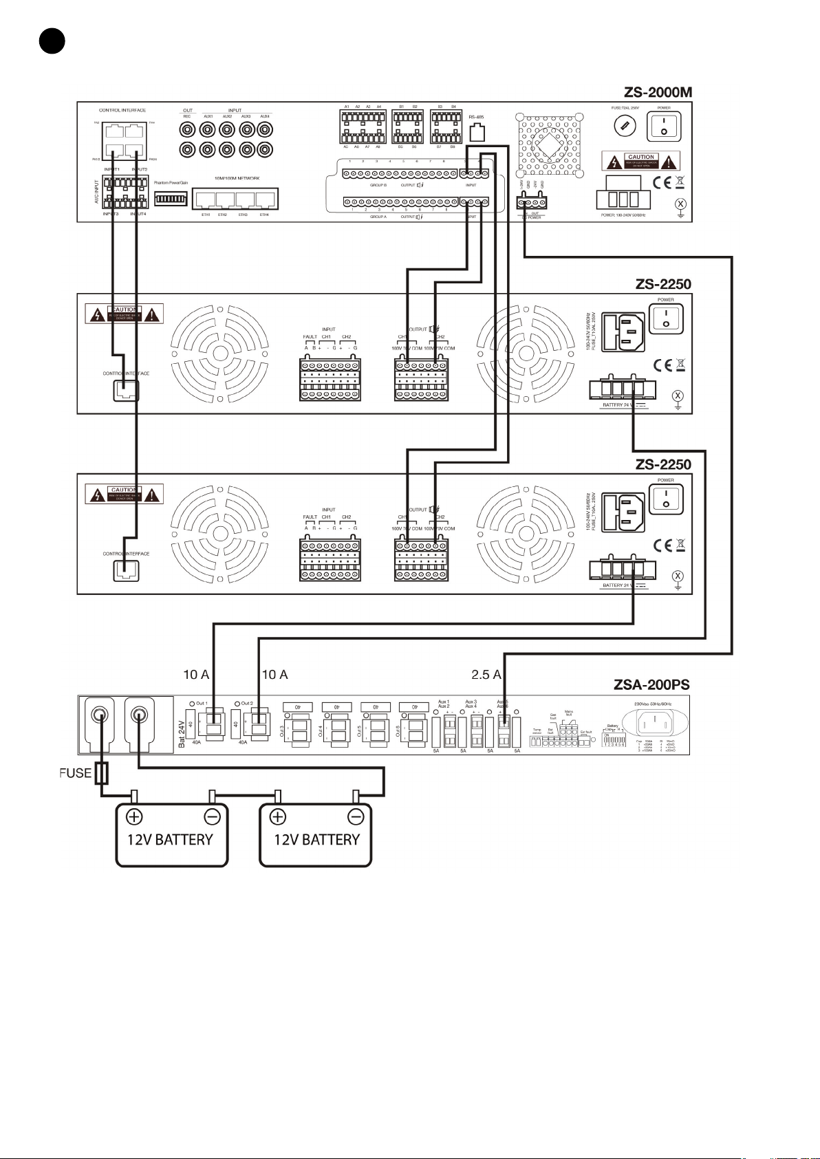
- Connection order:
1. All devices must be turned off
2. Configure the battery capacity values and the maximum resistance value of the battery circuit with the
DIPs located on the rear. Information relating to this setting can be found in the BATTERY
INSTALLATION AND CONFIGURATION section.
3. Connect the 24 V battery, including its fuse. The batteries must be fully charged in advance. Be careful
not to connect the terminals in reverse, as this could cause serious damage to both the power supply
and the connected devices.
4. Connect all amplifiers and other system equipment to the power supply ZSA-200PS.
5. Check (trials explained below):
-Battery circuit: The device periodically measures the resistance of the battery circuit. You can also
start the battery resistance test manually by pressing the ST button for about 10 seconds. The
settings and values mentioned in the BATTERY INSTALLATION AND CONFIGURATION section
must be complied with. The resistance value of the battery circuit can be checked by means of the
PC application, connected to the device via USB. If the actual resistance is greater than the setting
of the DIP selectors, an error message will appear.
-Signaling and operation when the main power is cut: disconnect power from the mains. The
ZSA-200PS power supply should start operating in battery mode, supplying voltage to all outputs.
Check the presence of voltage and its value with a multimeter. In this state, the LEDs on the front
panel should be as follows:
- Mains: off
- Battery: on
- Charging: off
- Fault: on
- 6 -
EN
ZSA-200PS_MANUAL_(EN_ES_FR_PT)_20191128-2.qxp_Maquetación 1 28/11/19 11:27 Página 6

-The signaling relays MAINS FAULT and GEN FAULT will enter inactive mode (the status of the
relays can be checked by measuring the resistance between the relay terminals with a multimeter).
During this test, the equipment connected to the power supply must operate normally.
-Signaling and operation when the battery is disconnected: with the device powered by the mains,
disconnect the batteries. This must be detected in the next test, which can take up to 100 seconds.
In this state, the LEDs on the front panel should be as follows:
- Mains: on
- Battery: off
- Charging: off
- Fault: on
The signaling relays BAT FAULT and GEN FAULT will go into inactive mode. During this test, the
equipment connected to the power supply must operate norma.
- 7 -
EN
ZSA-200PS_MANUAL_(EN_ES_FR_PT)_20191128-2.qxp_Maquetación 1 28/11/19 11:27 Página 7

CONNECTION EXAMPLE
- 8 -
EN
ZSA-200PS_MANUAL_(EN_ES_FR_PT)_20191128-2.qxp_Maquetación 1 28/11/19 11:27 Página 8

SOFTWARE
The ZSA-200PS power supply can be configured using PC software. To download the software, go to
fonestar.com and search for the product ZSA-200PS. Then open the "Software" tab to download the file to
your computer and install the software.
Select the power supply model and click Connect. After connecting, the State tab will be displayed.
The software has 4 configuration and information display tabs, as well as a button that can access the list
of error messages.
1.- State: shows the state of the mains connection, the protection relays LVDD and BD, as well as all the
information concerning voltages and currents in the batteries and the AUX and OUT outputs.
LVDD (Low Battery Disconnecting Device): protects against a total discharge of the battery.
BD: protects the AUX outputs in the event that the battery terminals or the OUT outputs are short-circuited
and the battery is not connected. Guarantees that the voltage remains in the AUX outputs despite battery
failure.
- 9 -
EN
ZSA-200PS_MANUAL_(EN_ES_FR_PT)_20191128-2.qxp_Maquetación 1 28/11/19 11:27 Página 9

2.- History: shows the history of events (power on, measurements, state changes...) with date, time and
temperature measurements, current intensities, voltages, etc.
To download the list of events just click the "Download" button.
3.- Setup: allows you to configure the parameters for the operation of the power supply ZSA-200PS.
- 10 -
EN
ZSA-200PS_MANUAL_(EN_ES_FR_PT)_20191128-2.qxp_Maquetación 1 28/11/19 11:27 Página 10

4.- Configuration: allows for the configuration of the battery operation mode. The modes to choose from are
“Continuous battery mode (Floating)” and “Non continuous battery mode”.
Continuous battery mode (Floating)
Non-continuous battery mode.
-Faults: displays error messages about batteries, fuses, power supply, etc. Warnings are automatically
cleared as they are detected to have been solved.
- 11 -
EN
ZSA-200PS_MANUAL_(EN_ES_FR_PT)_20191128-2.qxp_Maquetación 1 28/11/19 11:27 Página 11

DESCRIPCIÓN
Fuente de alimentación controlada por microprocesador.
Permite realizar la carga y el control de las baterías de emergencia de forma continua para que, en caso de
de fallo del suministro eléctrico, poder proporcionar alimentación al sistema de megafonía y alarma por voz.
CONTROLES Y FUNCIONES
PANEL FRONTAL
1.- MAINS: indicador luminoso de color verde. Este indicador permanecerá encendido siempre que detecte
que está recibiendo corriente electrica de forma correcta. Cuando el indicador esté apagado puede
indicar que existe un error que se debe rectificar o que no recibe alimentación de forma correcta.
2.- BATTERY: indicador luminoso de color amarillo. Este indicador está apagado cuando detecte un
funcionamiento correcto de las baterias conectadas. El indicador luminoso se enciende cuando las
baterías comienzan a suministrar la alimentación al resto de equipos conectados a las salidas de la
fuente de alimentación ZSA-200PS.
3.- CHARGING: indicador luminoso de color verde. Este indicador se enciende de forma intermitente
cuando se está realizando la carga principal de las baterías. Permanece encendido durante el proceso
de mantenimiento de carga de las baterías. Y está apagado cuando las baterías están cargadas
completamente.
4.- FAULT: indicador luminoso de color amarillo. Este indicador permanerá apagado siempre que el
funcionamiento general del equipo sea normal. El indicador se encenderá cuando detecte un fallo en la
entrega de alimentación a los equipos conectados o existe algún fallo interno y/o externo. Y se
encenderá intermitentemente cuando detecte señal en en la entrada EXT FAULT indicando que hay
algún fallo externo.
5.- ST: pulsador multifunción.
- Encendido en frío: cuando existe un fallo de suministro eléctrico, una pulsación larga de este botón
permite activar la alimentación en las salidas. Para ello, la carga de las baterías siempre debe ser
superior a 22 V.
-Test de resistencia de circuito de batería: una pulsación larga de unos 10 segundos de este botón
permite iniciar manualmente el test de resistencia del circuito de batería. El valor de esta resistencia
se toma periódicamente de forma automática. Solo será posible realizar este test con baterías
cargadas previamente.
-Borrado de alarmas: una pulsación corta de este botón eliminará los avisos de fallos internos en el
circuito regulador de la carga o errores en el chequeo de la memoria EPROM.
6.- USB: mediante una aplicación para PC permite realizar las siguientes funciones:
- Medir resistencia del circuito de baterías.
- Monitorear corriente de carga de baterías.
- Medir corriente de salidas AUX.
- Medir corriente de salidas OUT cuando hay alimentación de la red eléctrica.
- Seleccionar el modo de operación de las baterías.
-Realizar pruebas de diagnóstico, comprobar parámetros de funcionamiento y modificar la
configuración por defecto de la fuente de alimentación.
Más información en el apartado SOFTWARE.
- 12 -
ES
ZSA-200PS_MANUAL_(EN_ES_FR_PT)_20191128-2.qxp_Maquetación 1 28/11/19 11:27 Página 12

PANEL POSTERIOR
1.- Bornes para la conexión de la batería de 24 V, tipo VRLA-AGM. La carga mínima que puede tener la
batería para un correcto funcionamiento es 22 V siempre que los equipos conectados no requieran más
voltaje.
2.- OUT 1-6:
a.- indicador luminoso del estado del fusible. Este
indicador se encenderá cuando el fusible deba
ser sustituido. Por el contrario, el indicador
luminoso permanecerá apagado cuando el
fusible esté en perfecto estado.
b.- fusible de seguridad de 40 A independiente para
cada una de las entradas.
c.- salidas de alimentación para equipos de hasta
40 A, terminales euroblock. Permite conectar amplificadores de hasta 1.000 W en cada salida.
Deberá utilizar un cable de 6 mm2de sección para evitar que la tensión caiga por debajo de 0’2 V
durante un aviso de incendio.
3. AUX 1-4:
a.- indicador luminoso del estado del fusible. Este indicador se encenderá
cuando el fusible deba ser sustituido. Por el contrario, el indicador luminoso
permanecerá apagado cuando el fusible esté en perfecto estado.
b.- fusible de seguridad de 5 A para cada par de entradas.
c.- salidas dobles de alimentación. Puede conectar en cada par de entradas
equipos de hasta 5 A en total, terminales euroblock.
4. AUX 5-6:
a.- indicador luminoso del estado del fusible. Este indicador se encenderá cuando el
fusible deba ser sustituido. Por el contrario, el indicador luminoso permanecerá
apagado cuando el fusible esté en perfecto estado.
b.- fusible de seguridad de 5 A para cada una de las entradas.
c.- salidas de alimentación para equipos de hasta 5 A, terminales euroblock.
5.- TEMP SENSOR:entrada de señal para un sensor de temperatura, terminales euroblock.
Este sensor debe colocarse entre las baterías, en contacto directo con ambas.
6.- BAT FAULT: relé indicador de fallo de las baterías, terminales euroblock. Permanecerá
cortocircuitado durante el correcto funcionamiento de las baterías. Se abrirá el circuito si se desconecta
la batería, si la resistencia del circuito de batería es muy alta, o si el voltaje de la batería disminuye por
debajo de un nivel preestablecido.
7.- MAINS FAULT: relé indicador de fallo en el suministro eléctrico, terminales euroblock. Permanecerá
cortocircuitado mientras se reciba correctamente suministro de la red eléctrica. Se abrirá el circuito si
deja de recibirse suministro de la red o si hay una avería en el rectificador.
8.- GEN FAULT: relé indicador de fallo general, terminales euroblock. Permanecerá cortocircuitado mientras
no se detecten averías. Se abrirá el circuito si se detectan averías en la fuente de alimentación o una
avería externa.
9.- EXT FAULT: entrada externa para recibir la señalización de errores externos, terminales euroblock. Por
defecto esta entrada está cortocircuitada con un jumper indicando así que no hay fallos externos. Esta
entrada se activa abriendo el circuito entre ambos terminales. Para hacer uso de esta entrada debe
retirar el jumper y colocar un equipo que permita señalizar la existencia de errores mediante circuito
abierto y la ausencia de errores mediante circuito cerrado.
- 13 -
ES
ZSA-200PS_MANUAL_(EN_ES_FR_PT)_20191128-2.qxp_Maquetación 1 28/11/19 11:27 Página 13

10.- EXT FAULT LED: indicador luminoso de la presencia de fallos externos.
11.- BATTERY (CAP, RI): ajuste para el correcto funcionamiento de la batería, microinterruptores DIP. En el
apartado INSTALACIÓN Y CONFIGURACIÓN DE LA BATERÍA encontrará más detalles de este ajuste.
12.- Entrada de alimentación 230 V.
INFORMACIÓN IMPORTANTE
LUGAR DE INSTALACIÓN
-Para conservar los equipos en unas condiciones óptimas y alargar su vida útil se recomienda instalar los
equipos en un lugar:
- Temperatura ambiente: -40 a +85 ºC (en almacenaje) y -5 a +45 ºC (en funcionamiento).
- Humedad relativa: 80 % máx.
- Evitar que los rayos del sol incidan directamente.
- Evitar impactos, especialmente durante el funcionamiento.
-Diseñado para ser instalado en un rack de 19” con grado de protección IP30. El dispositivo ofrece
grado de protección IP20.
-Para instalar el dispositivo en el rack debe usar carriles guía. Éstos deberán instalarse de tal modo que
no cubran las ranuras de ventilación a los lados del equipo, ya que podría dañarse el equipo.
-El equipo ha de disponer de 8 cm de espacio libre a cada lado, permitiendo su adecuada ventilación.
-El equipo debe ser alimentado mediante un conector con conexión de tierra que sirva de protección.
-El mantenimiento del dispositivo debe ser suministrado por el fabricante o un tercero autorizado por
el fabricante.
-No desmonte el equipo, que podría tener componentes cargados. Tocar los componentes internos
tiene un alto riesgo de shock eléctrico o quemaduras en la piel.
CAPACIDAD DE LA BATERÍA
-Este equipo dispone de una corriente 16 A proporcionada por la fuente de alimentación que se reparte
entre las salidas AUX y el proceso de carga de la batería. Esto hace que la capacidad de la batería se vea
limitada por la corriente de las salidas AUX de la siguiente manera:
- La fuente de alimentación ZSA-200PS admite baterías de hasta 270 Ah de capacidad.
SALIDAS OUT Y AUX
-Los amplificadores del sistema de evacuación de emergencia se conectarán a las salidas OUT. En estas
salidas:
-Cuando hay alimentación de la red eléctrica, las salidas OUT de la fuente de alimentación ZSA-200PS
no suministrarán corriente. Las salidas AUX suministrarán corriente en todo momento.
-Cuando no hay alimentación de la red eléctrica, las salidas OUT de la fuente de alimentación
ZSA-200PS suministrarán corriente desde las baterías. Si hay alarma de incendio, la corriente
suministrada a las salidas OUT será mayor para alimentar los amplificadores del sistema de
evacuación de emergencia, necesario para transmitir mensajes de voz y señales de alarma en las
zonas de incendio.
-Los demás componentes del sistema de evacuación de emergencia (controladores, routers, estaciones
de llamada, etc.) que necesitan relativamente poca corriente de manera continua, no necesitarán estar
conectados a la red eléctrica. Se conectarán a las salidas AUX, que proporcionarán corriente de manera
ininterrumpida.
Corriente máxima proporcionada a
las salidas AUX 0-6 A 7 A 8 A 9 A 10 A 11 A 12 A
Capacidad máxima de la batería 270 Ah 240 Ah 210 Ah 180 Ah 160 Ah 130 Ah ≤100 Ah
- 14 -
ES
ZSA-200PS_MANUAL_(EN_ES_FR_PT)_20191128-2.qxp_Maquetación 1 28/11/19 11:27 Página 14

INSTALACIÓN Y CONFIGURACIÓN DE LA BATERÍA
IMPORTANTE: para conectar la batería, asegurese que la batería tiene carga completa y el equipo está
desconectado de la alimentación. Conecte primero el polo positivo y después el negativo; conectados estos
cables en sus terminales, una ambos cables colocándolos en paralelo y ajuste firmemente todas las
conexiones. Si lo que quiere es reemplazar la batería, también debe hacerlo con el equipo desconectado de
la alimentación pero en orden inverso a la conexión,es decir, primero desconectaremos el polo negativo y
después el positivo.
-Las baterías que conecte en los bornes deben proporcionar un voltaje total de 24 V y ser revisadas
periodicamente para asegurar que siempre las baterías conectadas al equipo se encuentran en buen
estado y listas para funcionar. Si conecta varias baterías tenga en cuenta que deben estar conectadas
en serie y los cables no deben superar los 2 metros en total.
-Asegurese que no se producen caidas de tensión superiores a 0’6 V utilizando el cable adecuado para
su instalación. A continuación encontrará una tabla orientativa:
-Por último, ajuste los valores de los microinterruptores del panel trasero (BATTERY). Los 3 primeros
sirven para indicar la capacidad de la batería y los 3 últimos para indicar el valor máximo de resistencia
del circuto de batería. Ambos valores se componen de la suma de los valores de los DIP.
-CAP: el valor mínimo es de 50 Ah. A este valor se le puede sumar 50 Ah (DIP 1), 50 Ah (DIP 2) y 100
Ah (DIP 3), pudiendo alcanzar el valor máximo de 250 Ah cuando los 3 DIP estén en la posición de ON
(arriba). Debe seleccionarse un valor cercano o superior a la capacidad real de las baterías.
-Ri: el valor mínimo es de 15 mΩ. A este valor se le puede sumar 5 mΩ(DIP 4), 10 mΩ(DIP 5) y 20 mΩh
(DIP 6), pudiendo alcanzar el valor máximo de 50 mΩcuando los 3 DIP estén en la posición de ON
(arriba). El valor a elegir dependerá de la potencia total de los altavoces de la instalación. Para altavoces
con potencia superior a 500 W, el ajuse del límite para la resistencia del circuito de batería deberá ser
menor. Utilice la siguiente tabla para determinar la posición de los selectores DIP según su instalación.
En la práctica, el ajuste de resistencia máxima deberá ser mayor que el valor real, y el margen tiene que
tener en cuenta el aumento de resistencia debido a el envejecimiento de las baterías.
Potencia de
altavoces (Pa) [W] Sección de cable Resistencia de los cables y
fusible de la batería [mΩ]
Pa ≤ 1500 W 10 mm2[1’8 mΩ/1m] ≤ 10 mΩ
1500 W < Pa ≤ 3000 W 25 mm2[0’7 mΩ/1m] ≤ 6 mΩ
3000 W < Pa ≤ 6000 W 35 mm2[0’5 mΩ/1m] ≤ 3 mΩ
Potencia de
altavoces [W]
Resistencia prevista en
circuito de batería [m] *
Resistencia Ri máxima del
circuito de batería [m]
Margen de
resistencia [m]
500 ≤ 30 50 20
1000 ≤ 25 45 20
1500 ≤ 19 35 16
2000
2500 ≤ 16 30 14
3000
3500 ≤ 11 20 9
4000
4500
5000
5500
6000
≤ 9 15 6
- 15 -
ES
ZSA-200PS_MANUAL_(EN_ES_FR_PT)_20191128-2.qxp_Maquetación 1 28/11/19 11:27 Página 15

MODOS DE FUNCIONAMIENTO
-Modo flotante: cuando se recibe suministro eléctrico de la red, el cargador de la fuente de alimentación
ZSA-200PS mantiene las baterías en estado de carga completa. El funcionamiento del cargador es
gestionado por el controlador del microprocesador de la fuente de alimentación ZSA-200PS que
supervisa las baterías de forma independiente, manteniendo el voltaje de modo flotante. El voltaje de
este modo depende de la temperatura ambiente cuando tenga conectado el sensor de temperatura. Si
no se ha conectado el sensor de temperatura, el controlador mantendrá el voltaje correspondiente a una
temperatura ambiente de 25 ºC.
-Modo con carga de baterías no continua: este modo es activado cuando hay suministro eléctrico de
la red, se han cargado completamente las baterías, y se ha mantenido el modo flotante durante 48 horas
(por defecto). Después de cumplirse las condiciones dadas, las baterías serán desconectadas
automáticamente del cargador. Este estado durará 18 días (por defecto) o hasta que el voltaje de la
baterías disminuya hasta el nivel de voltaje establecido. En ambos casos comenzará la carga de
mantenimiento. Una vez cargadas las baterías y habiendo mantenido el modo flotante durante 48 horas,
volverán a desconectarse las baterías durante 18 días (por defecto). Si el suministro eléctrico falla o se
detectan picos de corriente en las salidas, las baterías serán reconectadas inmediatamente para evitar
que la caída de la tensión supere 1 V.
- El modo de funcionamiento puede cambiarse solamente por USB mediante la aplicación para PC.
- Por defecto se usa la configuración de modo flotante.
IMPORTANTE: para alargar la vida útil de las baterías utilice el modo de funcionamiento de carga no continua.
INSTRUCCIONES DE CONEXIÓN
-La instalación del sistema debe ser realizada por personal cualificado para asegurar que el conexionado
se realiza de forma segura y conforme a los requerimientos tanto de cada uno de los equipos conectados
como del conjunto.
Además, en la primera instalación debe comprobarse todas las tensiones del sistema, conexiones
realizadas, estado de la batería, circuitos de señalización, así como el funcionamiento de los equipos
para todos los escenarios posibles.
-El equipo no dispone de interruptor de encendido, por tanto, será necesario usar un interruptor externo
con protección de sobrecarga y cortocircuito.
- Orden de conexión:
1. Todos los equipos deben estar apagados
2. Configurar los valores de capacidad capacidad de la batería y el valor máximo de resistencia del
circuto de batería con los DIP situados en la trasera. Encontrará información relativa a este ajuste en
el apartado INSTALACIÓN Y CONFIGURACIÓN DE LA BATERÍA.
3. Conecte la batería de 24 V incluyendo el fusible para esta. Las baterías deberán estar completamente
cargadas previamente. Tenga cuidado de no conectar los terminales de forma inversa, pues podría
causar daños graves tanto a la fuente de alimentación como a los dispositivos conectados.
4. Conecte todos los amplificadores y demás equipos del sistema a la fuente de alimentación
ZSA-200PS.
5. Compruebe (pruebas explicadas a continuación):
-Circuito de batería: el equipo mide periódicamente la resistencia del circuito de baterías. También
puede iniciarse el test de resistencia de baterías manualmente pulsando el botón ST durante unos
10 segundos. Deben cumplirse los ajustes y valores mencionados en el apartado INSTALACIÓN
Y CONFIGURACIÓN DE LA BATERÍA. Se podrá comprobar el valor de la resistencia del circuito de
baterías mediante la aplicación para PC, conectado por USB al dispositivo. Si la resistencia real es
mayor que el ajuste de los selectores DIP, se generará un aviso de error.
-Señalización y funcionamiento cuando se produce un corte en la alimentación principal: desconecte
la alimentación de la red eléctrica. La fuente de alimentación ZSA-200PS deberá comenzar a
funcionar en modo de batería, suministrando voltaje a todas las salidas.Compruebe la presencia
de voltaje y su valor con un polímetro. En este estado, los LEDs del panel frontal deberán
encontrarse de la siguiente manera:
- 16 -
ES
ZSA-200PS_MANUAL_(EN_ES_FR_PT)_20191128-2.qxp_Maquetación 1 28/11/19 11:27 Página 16

- Mains: apagado
- Battery: encendido
- Charging: apagado
- Fault: encendido
Los relés de señalización MAINS FAULT y GEN FAULT entrarán en modo inactivo (el estado de los
relés puede comprobarse midiendo la resistencia entre los bornes del relé con un polímetro).
Durante esta prueba, los equipos conectados a la fuente de alimentación deberán funcionar con
normalidad.
-Señalización y funcionamiento cuando la batería está desconectada: con el dispositivo alimentado
por la red eléctrica, desconecte las baterías. Este estado debe detectarse en el siguiente test, que
puede tomar hasta 100 segundos. En este estado, los LEDs del panel frontal deberán encontrarse
de la siguiente manera:
- Mains: encendido
- Battery: apagado
- Charging: apagado
- Fault: encendido
Los relés de señalización BAT FAULT y GEN FAULT entrarán en modo inactivo. Durante esta
prueba, los equipos conectados a la fuente de alimentación deberán funcionar con normalidad.
- 17 -
ES
ZSA-200PS_MANUAL_(EN_ES_FR_PT)_20191128-2.qxp_Maquetación 1 28/11/19 11:27 Página 17

EJEMPLO DE CONEXIÓN
- 18 -
ES
ZSA-200PS_MANUAL_(EN_ES_FR_PT)_20191128-2.qxp_Maquetación 1 28/11/19 11:27 Página 18

SOFTWARE
La fuente de alimentación ZSA-200PS se configura mediante software para PC. Para descargar el software,
acceda a nuestra WEB fonestar.com y busque el producto ZSA-200PS. A continuación, abra la pestaña
“Software” para descargar el archivo en su ordenador e instale el software.
Seleccione el modelo de la fuente de alimentación y haga clic en Connect. Tras conectar se mostrará la
pestaña State.
El software dispone de 4 pestañas de visualización de información y configuración, y un botón de acceso a
la lista de avisos de error.
1.- State: muestra el estado de la conexión a la red eléctrica, los relés de protección LVDD y BD, así como
toda la información relativa a voltajes e intensidades de corriente en las baterías y las salidas AUX y OUT.
LVDD (Low Battery Disconnecting Device): protege contra una descarga total de la batería.
BD: protege las salidas AUX en caso de cortocircuito en los terminales de las baterías o las salidas OUT
y la batería no está conectada. Garantiza que permanezca el voltaje en las salidas AUX a pesar de fallo
en las baterías.
- 19 -
ES
ZSA-200PS_MANUAL_(EN_ES_FR_PT)_20191128-2.qxp_Maquetación 1 28/11/19 11:27 Página 19

2.- History: muestra el historial de eventos (encendido, medidas, cambios de estado...) con fecha, hora y
medidas de temperatura, intensidades de corriente, voltajes, etc.).
Para descargar la lista de eventos basta con hacer click en el botón “Download”.
3.- Setup: permite la configuración de los parámetros para el funcionamiento de la fuente de alimentación
ZSA-200PS.
- 20 -
ES
ZSA-200PS_MANUAL_(EN_ES_FR_PT)_20191128-2.qxp_Maquetación 1 28/11/19 11:27 Página 20
Table of contents
Languages:
Other FONESTAR Power Supply manuals
Popular Power Supply manuals by other brands

Emerson
Emerson Sola HD GLQ250 Series Installation & operating instructions

Atomos
Atomos Power Station Photo ATOMPWS001 quick start guide

Seneca
Seneca Z-SUPPLY quick start guide

WAGO
WAGO Pro 2 manual

Genetec
Genetec SY-SIX-PSU-DIN-8A installation manual

Phoenix Mecano
Phoenix Mecano WIENER MTCA.4 1000W PS user manual