Forno Alfa Qualita FCTGS5751-30 User manual
GAS RANGETOP
INSTALLATION GUIDE
SPECIFICATIONS, INSTALLATION, AND MORE
MODEL NUMBERS:
FCTGS5751-30 FCTGS5751-36 FCTGS5751-48

2
3
4
Important Safety Information 6
8
9
Cooktop Burner Grills Installation 10
Electrical 10
Gas Supply 11
Pressure Regulator 12
Gas Shut-off Valve 12
Product Dimensions and Cabinets 13
Exhaust Hood Installation 16
Gas Conversion Operation 16
Gas Supply Connection 20
Ignition
20
21
Simmer and Boil 21
Burner Grates 22
Griddle Operation 22
Cooktop Cleaning Tips 22
22
23
24
Wire Diagram
Features of You Rangetop

Thank you for purchasing a FORNO product. Please read the entire instruction manual before operating
your new appliance for the first time. Whether you are an occasional user or an expert , it will be beneficial
to familiarize yourself with the safety practices, features, operation and care recommendations of your
appliance.
Both the model and serial number are listed inside the product. For warranty purposes, you will also need
the serial number, the date of purchase & a copy of your proof of purchase.
Record this information below for future reference.
Use these number in any correspondance or
service calls concerning your product.
If you received a damaged product,
immediately contact FORNO.
Save time and money. Before you call for
service, check the Troubleshooting Guide. It
lists the causes of minor operating problems
that you can correct yourself.
SERVICE IN CANADA & UNITED STATES
Keep the instruction manual handy to answer your questions. You can also find all the information
you need online at www.fornoappliances.com.
If you don't understand something or you need more assistance, please visit our website or call
our Customer service: 1 866-231-8893 opt.2 ext.214
Or email : [email protected]
If there is a problem, please contact FORNO customer service. All warranty work needs to be
authorized by FORNO customer service. All of our authorized service providers are carefully
selected and rigorously trained by us.
3

4
Your safety and the safety of others are very important.
We have provided many important safety messages in this manual and on your appliance.
Always read and obey all safety messages.
This is a safety alert symbol. It will alert you to potential personal or property safety hazards.
Obey all safety messages to avoid any property damage, personal injury or death.
WARNING indicates a potentially hazardous situation which, if not avoided, could result in
serious injury or death.
CAUTION indicates a moderate hazardous situation which, if not avoided, could result in
minor or moderate injury.
All safety messages will alert you what the potential hazard is, tell you how to reduce the
chance of injury, and let you know what can happen if the instructions are not followed.
- WHAT TO DO IF YOU SMELL GAS
•Do not try to light any appliance.
•Do not touch any electrical switch.
•Do not use any phone in your building.
• Immediately call your gas supplier from a neighbor’s phone. Follow the gas supplier’s
instructions.
•If you cannot reach your gas supplier, call the fire department.
Rangetop Safety

5
The installation must conform with local codes or, in the absence of local codes, with the National
Fuel Gas Code, ANSI Z223.1/NFPA 54 or, in Canada, the Natural Gas and Propane Installation
Code, CSA B149.1.
WARNING
This product can expose you to chemicals including carbon monoxide, which is known to the
State of California to cause developmental harm.
For more information go to www.P65Warnings.ca.gov
WARNING
Never operate the top surface cooking section of the appliance unattended
Failure to follow this warning statement may result in fire, explosion or burn hazard that could
cause property damage, personal injury or death.
If a fire should occur, keep away from the appliance and immediately call your fire
department. DO NOT ATTEND TO EXTINGUISH AN OIL/GREASE FIRE WITH WATER
Read all safety instructions before using the product. Failure to follow these
instructions may result in fire, electrical shock, serious injury or death.

6
Extremely Heavy.
Proper equipment and adequate manpower are needed when move the rangetop to
avoid personal injury or damage to the unit or the floor.
Failure to follow this advice may result in damage or personal injury.
1. Use this rangetop for its intended purpose as described in this instruction manual.
2. Have your rangetop installed and properly grounded by a qualified installer in accordance
with the provided installation instructions.
3. Any adjustment and service should be performed only by a qualified rangetop installer or
service technician. Do not attempt to repair or replace any part of your rangetop unless it is
specifically recommended in this manual.
4. Your rangetop is shipped from the factory set for use with natural gas or propane (LP) gas.
It can be converted for use with either. If required, these adjustments must be made by a
qualified technician in accordance with the installation instructions and local codes. The agency
performing this work assumes responsibility for the conversion.
5. Have the installer show you the location of the rangetop gas shut-off valve and how to turn it
off if necessary.
6. Plug your rangetop into a 120-volt grounded outlet only. Do not removed the round
grounding prong from the plug. If in doubt about the grounding of the home electrical
system, it is your responsibility and obligation to have an ungrounded outlet in accordance
with the National Electrical Code. Do not use an extension code with this rangetop.
7. Before performing any service, unplug the rangetop or disconnect the power supply at
the household distribution panel by removing the fuse or switching off the circuit breaker.
8. Be sure all packing materials are removed from the rangetop before operating to
prevent i gnition of these materials.
9.Do not leave children alone or unattended in an area where an appliance is in use. They
should never be allowed to climb, sit or stand on any part of the rangetop.
10.Never block the vents (air openings) of the rangetop. They provide the air inlets and
outlets that are necessary for the rangetop to operate properly with correct combustion.
11.Use only dry pot holders--moist or damp pot holders on hot surfaces may result in burns
from steam. Do not let pot holders touch surface burners, or burner grate. Do not use a
towel or other bulky fabrics in place of pot holders.
12.Do not heat unopened food containers. Pressure could build up and the container could
burst, causing any injury.
.
7
Never leave the surface burners unattended at medium or high heat settings. Foods, especially oily
foods, may ignite resulting in fire that could spread to surrounding cabinets.
Never leave oil unattended while frying. If allowed to heat beyond its smoking point, oil may ignite
resulting in fire that may spread to surrounding cabinets. Use a deep fat thermometer whenever
possible to monitor oil temperature.
To avoid oil spillover and fire, use the minimum amount of oil when frying in a shallow pan and
avoid cooking frozen foods with excessive amounts of ice.
Use proper pan size and avoid pans that are unstable or easily tipped. Select cookware that
matches the size of the burner. Burner flames should be adjusted so that they do not extend
beyond the bottom of the pan. Excessive flames may be hazardous.
To minimize the possibility of burns, ignition of flammable materials and spillage, cookware handles
should be turned toward the center of the rangetop without extending over nearby burners.
Do not use a wok with a round metal support ring. The ring may trap heat and block air to the
burner resulting in a carbon monoxide hazard.
Do not attempt to lift the cooktop. Doing so may damage the gas tubing to the surface burners
resulting in a gas leak and risk of fire.
Do not use aluminum foil to cover the grates or line any part of the cooktop. Doing so may result in
carbon monoxide poisoning, overheating of the cooktop surfaces, or a potential fire hazard.
Do not use water on grease fires. Never pick up a flaming pan. Turn the controls off. Smother a
flaming pan on a surface unit by covering the pan completely with a well-fitting lid, cookie sheet
or flat tray. Use a multi-purpose dry chemical or foam-type fire extinguisher.
Cook food thoroughly to help protect against foodborne illness. Minimum safe food temperature
recommendations can be found at www.IsItDoneYet.gov and www.fsis.usda.gov. Use a food
thermometer to take food temperatures and check several locations.
Keep the ventilator hood and grease filter clean to maintain good venting and to avoid grease
fires. Turn the ventilator OFF in case of a fire or when intentionally "flaming" liquor or other
spirits on the cooktop. The blower if in operation, could spread the flames.
TOP
Do not store or use flammable materials in an oven or near the cooktop, including paper,
plastic, pot holders, linens, wall coverings, curtains, drapes and gasoline or other flammable
vapors and liquids.
Never wear loose-fitting or hanging garments while using the appliance. These garments may
ignite if they contact hot surfaces causing severe burns.
Do not let cooking grease or other flammable materials accumulate in or near the range.
Grease on the cooktop may ignite.
8
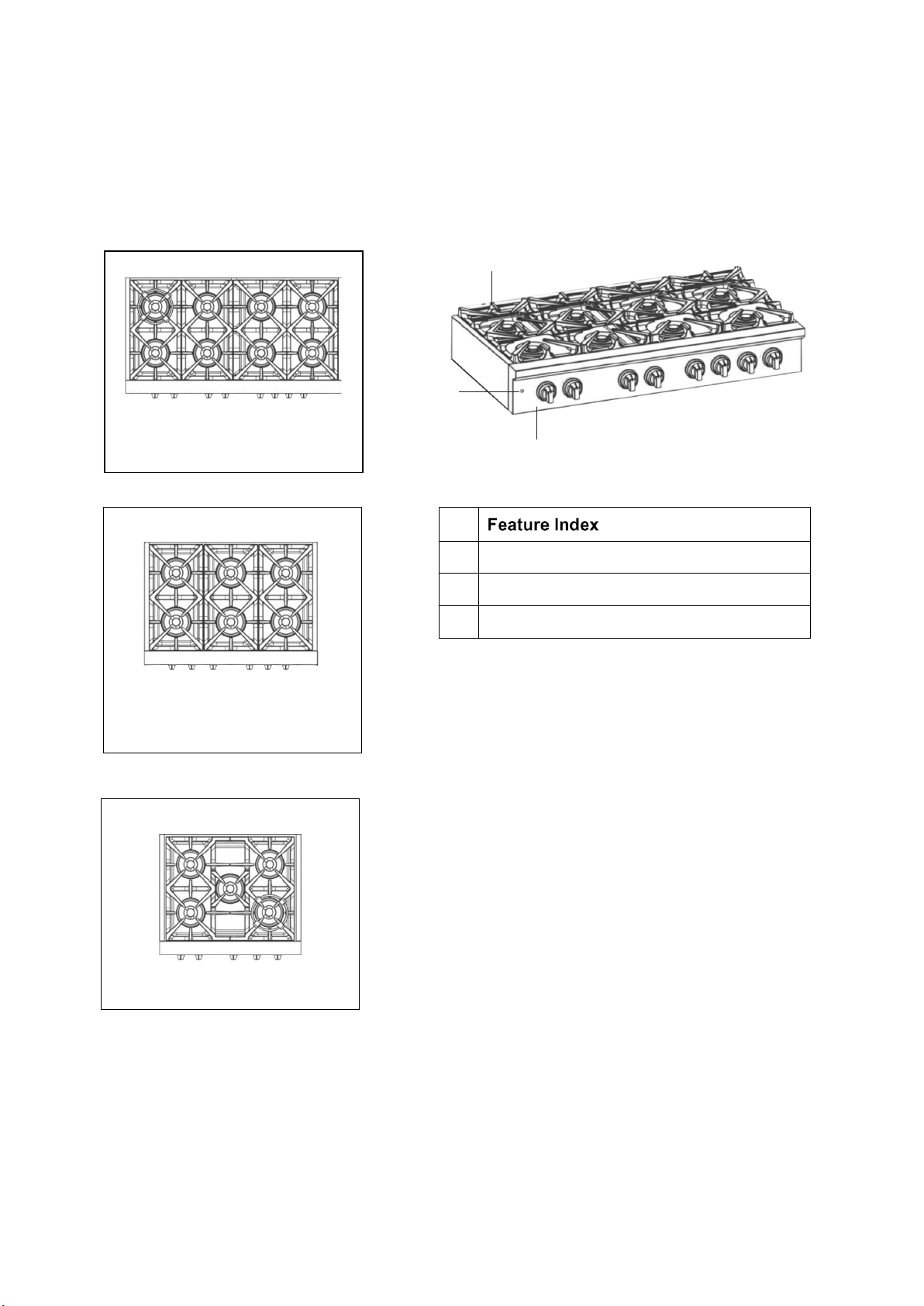
Features of Your Rangetop
Not all features are on all models. Appearance may vary.
1
2
Cooktop Burner Grates
3
Control Panel
6 burners
5 burners
8 burners
1
2
3
LED Light Switch

9
Installation Instructions
Before using your rangetop
1. Remove all packaging material.
2. Check to make sure you have all of the accessories listed below
LPG injector
FCTGS5751-30 15 pieces
FCTGS5751-36 18 pieces
FCTGS5751-48 24 pieces
Burner Grills FCTGS5751-30 2 pieces
Burner Grills
FCTGS5751-36 3 pieces
FCTGS5751-48 3 pieces
1 piece
Burner & Cap
(20000BTU)
FCTGS5751-30 5 sets
FCTGS5751-36 6 sets
FCTGS5751-48 8 sets
1 piece
Burner Grills FCTGS5751-48
Regulator (pre-installed) 1 piece
Serial Number Sticker & Instruction Manual 1 set
Cook plate (Griddle)
Wok Support 1 piece

10
YOU NEED TOOLS FOR INSTALLATION. (not supplied with the rangetop)
Screwdriver Wrench Socket wrench Allen key Tape measure
&Pencil
Protective
gloves Hammer Adjustable
wrench Adjustable
pliers
Drill
Cooktop Burner Grills Installation
Remove the packing materials from the cooktop burner
grills. Place the burner grills to the correct position. Check
the direction of middle grill on the right as illustrated, the
thicker side should be towards the left.
Put the cook plate (for FCTGS5751-48) and the wok support
to the burner(s) you like to cook. 48"
Electrical
Your rangetop must be electrically grounded in accordance with local codes or, in the absence of
local codes, in accordance with the National Electrical Code (ANSI/NFPA 70, latest edition). In
Canada, electrical grounding must be in accordance with the current CSA C22.1 Canadian
Electrical Code Part 1 and/or local codes.
The power supply must be the correct polarity. Reverse polarity will result in continuous sparking
of the electrodes, even after flame ignition. If there is any doubt as to whether the power supply
has the correct polarity or grounded, have it checked by a qualified electrician.
ELECTRICAL REQUIREMENTS
Electrical Supply
Service
Grounded, 110/120 VAC, 60 Hz
15 amp or 20 amp dedicated circuit
Receptacle 3-prong grounding-type
Power Cord 5' (1.3 m)

11
Gas Supply
Installation must comply with local codes or, in the absence of local codes, with the National Fuel
Gas Code, ANSI Z223.1 / NFPA 54. In Canada, installation must conform to the current natural
Gas Installation /code, CAN 1-1.1-M81 and with local codes where applicable.
This rangetop has been design-certified according to ANSI Z21.1b-2012 latest edition.
Ventilation: it is recommended that the unit be operated with an oven head, vented exhaust
hood of sufficient size and capacity.
this rangetop is equipped with a three-prong
(grounding) plug for your protection against shock hazard and should be plugged directly into a
properly grounded three-pronged receptacle.
cut or removes the grounding prong from the plug.
Label all wires prior to disconnection when servicing controls. Wiring errors can
cause improper and dangerous operation. Verify proper operation after servicing.
GAS REQUIREMENTS
NATURAL GAS WC
5" (12.5 mb)
6"
14" (34.9 mb), 0.5 psi (3.5 kPa)
Regulator Pressure
Minimum Supply Pressure
Maximum Supply Pressure
LP GAS WC
10" (25 mb)
Regulator Pressure
Minimum Supply Pressure
Maximum Supply Pressure
11"
14" (34.9 mb), 0.5 psi (3.5 kPa)
The min and max gas supply pressure stands for the pressure at the Gas Shut-Off Valve.
shock hazard from the rangetop.
12
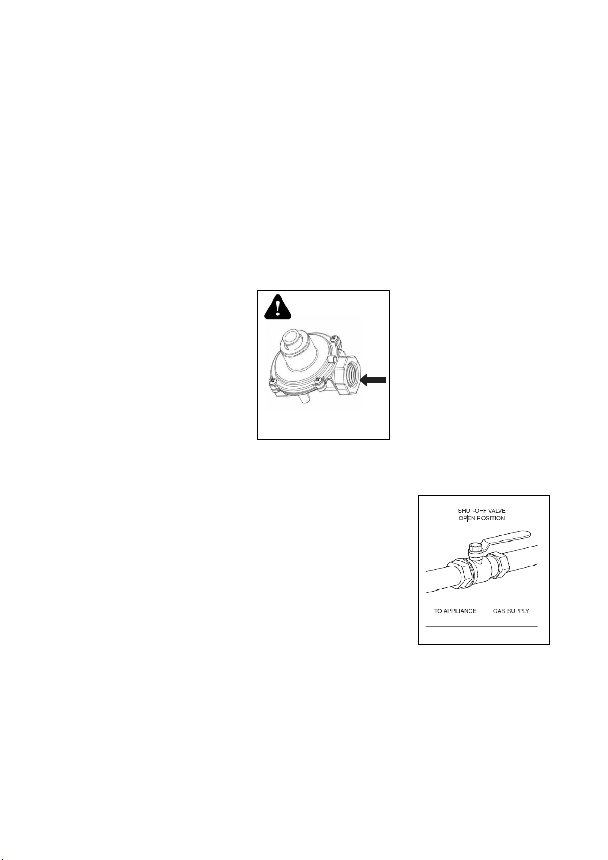
Gas Shut-off Valve
Pressure regulator can withstand
a maximum input pressure of 0.5
psi (3.5 kPa), and is set at 5"
WC outlet pressure when used
on NATURAL GAS and 10" WC
outlet pressure when used on
LIQUID PROPANE.
The supply line must be equipped with an approved external gas
shut-off valve located near the range in an accessible location. Do
not block access to the shut-off valve. Refer to the illustration below.
A 3/4" (19 mm) ID gas supply line must be provided to the range. If
local codes permit, a certified, 3' (.9 m) long, 1/2" (13 mm) or 3/4"
(19 mm) ID flexible metal appliance connector is recommended to
connect the unit’s 1/2" NPT (30" 36" 48") female inlet to the gas
supply line. Pipe joint compounds suitable for use with natural or LP
gas should be used.
The appliance and its shut-off valve must be disconnected from the gas supply piping system
during
any pressure testing of the system at test pressures in excess of 0.5 psi (3.5 kPa). The appliance
must be isolated from the gas supply piping system by closing its individual manual shutoff valve
during any pressure testing of the system at test pressures equal to or less than 0.5 psi (3.5 kPa).
(not included)
Pressure Regulator
Since service pressure may fluctuate with local demand, every rangetop must be equipped with a
pressure regulator on the incoming service line for safe and efficient operation.
The pressure regulator shipped with the range has two female threads 1/2" NPT for the 30" 36" and
the 48".
The regulator is preinstalled in order to be accessible when the appliance is installed in its final
position.
P
X
GAS INLET
Pressure Regulator
Gas Shut-off Valve

13
Product Dimensions and Cabinets
30"(762)
26" (665)
7"1/2 (190)
36" (914)
26" (665)
7"1/2 (190)
48" (1219)
26" (665)
7"1/2 (190)
FCTGS5751-36
FCTGS5751-30
FCTGS5751-48

Dimensions and Clearances
Recommended
gas and electrical
service location,
consult local code
B
10”" (25.4 cm) to
combustible side
wall min. both sides
1 1/2”" (3.8 cm)
typical countertop
thickness
7 1/2"
(19cm)
36" (91.4 cm)
typical
Mounting platform
1" (2.5 cm) min.
thickness
Cabinet/Countertop Dimensions - Front View
Cabinet tolerances ± 1/16" (± 1.6 mm) unless otherwise noted.
Cabinet/Countertop Dimensions - ISO View
1Vertical to combustible surface from rangetop grate level;
if installing an overhead vent hood, also check the hood
specifications for minimum required clearances.
2See Cabinet/Countertop Dimensions - Top View
3This specification not applicable for cabinets more
than a horizontal distance of 10" (25.4 cm) from the cabine.
Rangetop
Model B C
FCTGS5751-36 36" (91.4 cm) 36" (91.4 cm)
42" (106.7 cm)
FCTGS5751-48 48" (121.9 cm) 48" (121.9 cm)
54" (137.2 cm)
*MinimumMini Rec
**
**
*
*
mum **
FCTGS5751-30 30" (76.2 cm) 30" (76.2 cm)
36" (91.4 cm) **
*
For reference only, please refer to the real object.
14
See note 2
C
13" (33.0 cm)
max. 3
Top of
finished
counter
Grate
level Grate
level
15" (40.6 cm)
min.1, 3
40" (101.6 cm)
min.1
Cutout for
utility access

IMPORTANT: Use only the downdraft vent models specified.
Non-combustible
rear wall, rear of
mounting platform
10" (25.4 cm) min.
to combustible wall
above countertop,
both sides
Cabinet face
below countertop
overhang
Increase countertop and overhang
additional 2 1/2" (6.4 cm) min. for
combustible rear wall above
countertop
1/2" (1.3 cm)
countertop overhang
1" (2.5 cm) thick mounting platform min.
Countertop
Countertop
Counterop
overhang
1” (2.5 cm)
typical
1 7/10”
(4.35 cm)
max.
23.7"
cm)(60.2
min.
cabinet
depth
B
Installed Rangetop - Side View Gas connection and power cord may be
routed through bottom or back of chassis
Gas and electrical connections at
right rear section of chassis
Cabinet
face
Installed control
panel overhang
1/7/10" (4.35 cm)
23.7" (60.2 cm)
Countertop
Mounting platform
Cabinet/Countertop Dimensions (cont.)
Cabinet tolerances ±1/16" (±1.6mm) unless otherwise noted.
FOR FCTGS5751-30
FCTGS5751-36
11.4" (29cm)
FOR FCTGS5751-48
For reference only, please refer to the real object.
15
16
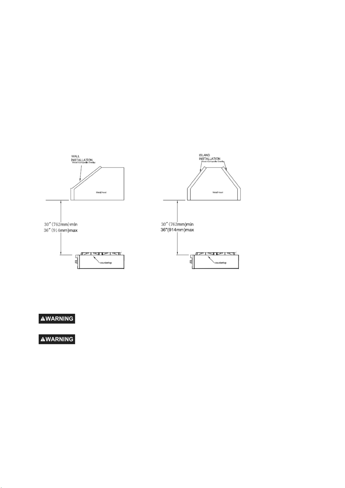
Exhaust Hood Installation
The bottom of the hood should be 30" min. to 36" above the countertop. This would typically result
in the bottom of the hood being 66" to 72" above the floor. These dimensions provide safe and
efficient operation of the hood.
After Installation:
1. Check ignition of cooktop burners.
2. Check the air shutter adjustment – sharp blue flame, with no yellow tipping or lifting flames.
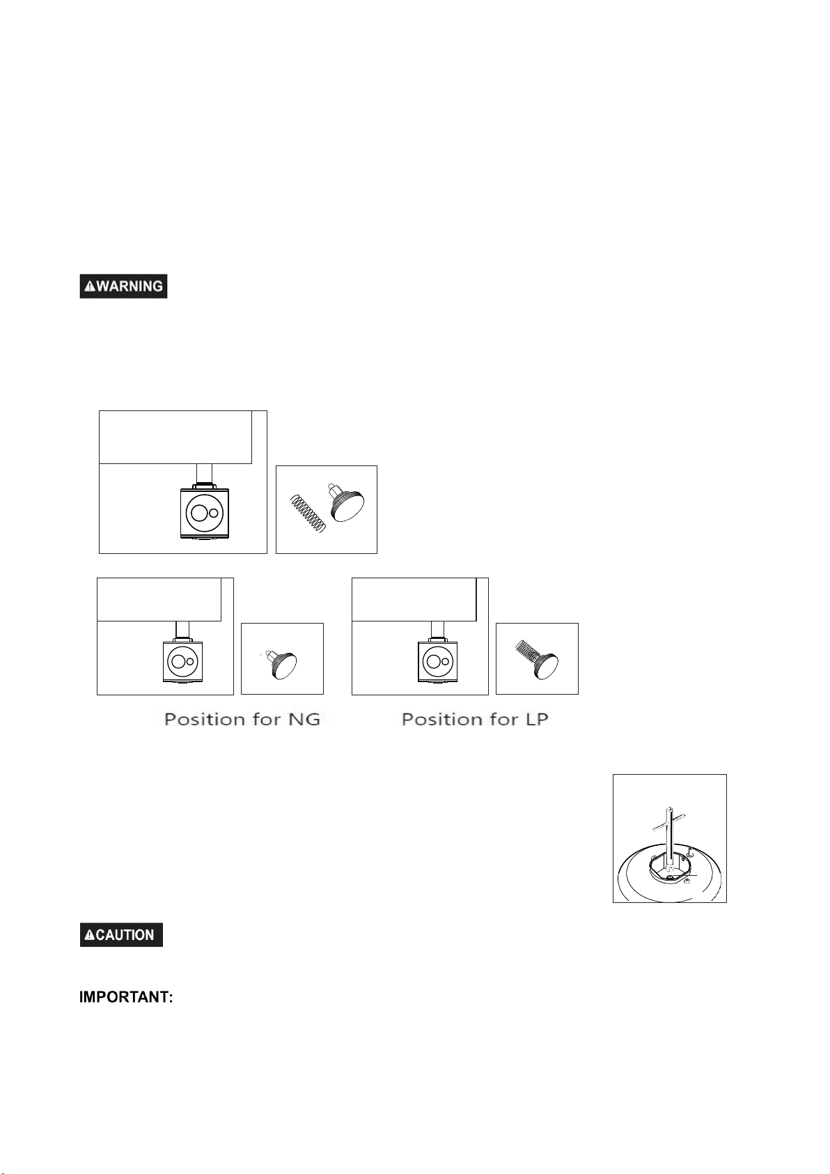
Gas Conversion Operation
This rangetop can be used with LP gas and NG gas. It is shipped from the factory adjusted for
use with NG(Nature Gas). Conversion nozzles are included. Follow the instruction shown
below for gas conversion.
Gas conversion shall be conducted by a factory- trained professional. Call
the
customer service hotline to identify a factory-trained professional near your home.
Before carrying out this operation, disconnect the rangetop from gas and electricity.
1. Pressure regulator 5. Installation of new rating label
2. Cooktop burners
3. Gas valves
4. Reconnect Gas and Electrical Supply
The gas conversion procedure for this range includes 5 steps:
17
The conversion is not completed if all 5 steps have not been concluded properly.
Before performing the gas conversion, locate the package containing the replacement nozzles
shipped with every rangetop.
STEP 1: Pressure Regulator
To access the gas regulator, pull the rangetop away from the cabinet wall. The
gas regulator is located at the back of the rangetop.
Electrical shock hazard can occur and result in injury or death. Disconnect electrical
power to the rangetop before servicing. Do not remove regulator or allow it to turn during
servicing.
a. Unscrew the cap from the regulator. Do not remove the spring from the regulator.
b. Unscrew the insert from the cap and turn it over so the longer stem is facing the cap. Replace
insert on the cap. Replace the cap on the regulator.
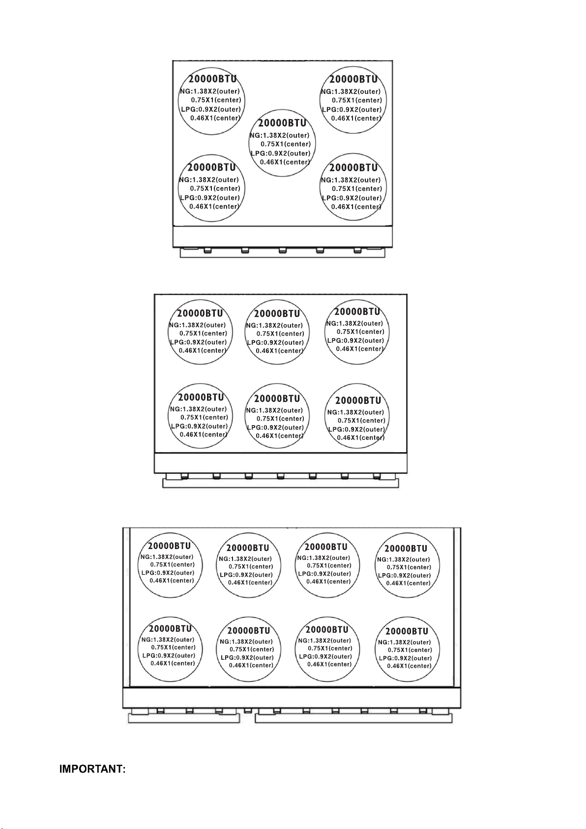
STEP 2: Cooktop Burners
a. Remove cooking grates, burner caps and inner burner rings.
b. Lift off outer burner heads and burner bases.
c. Remove the factory installed natural gas nozzles from the center
of the nozzle holders using a 7mm socket wrench. Replace the LP
nozzle in each nozzle holder. Tighten each nozzle until snug. Use
caution not to over tighten.
Care should be taken when removing and replacing gas
components. Use proper support to prevent damage to components.
Socket Wrench
Each nozzle has a number indicating its flow diameter printed on the body. Consult
the table below for matching nozzles and burners.
Å
ÅÅ
18
Model:FCTGS5751-30
Model:FCTGS5751-36
Model:FCTGS5751-48
Save the nozzles removed from the rangetop for future use.
19
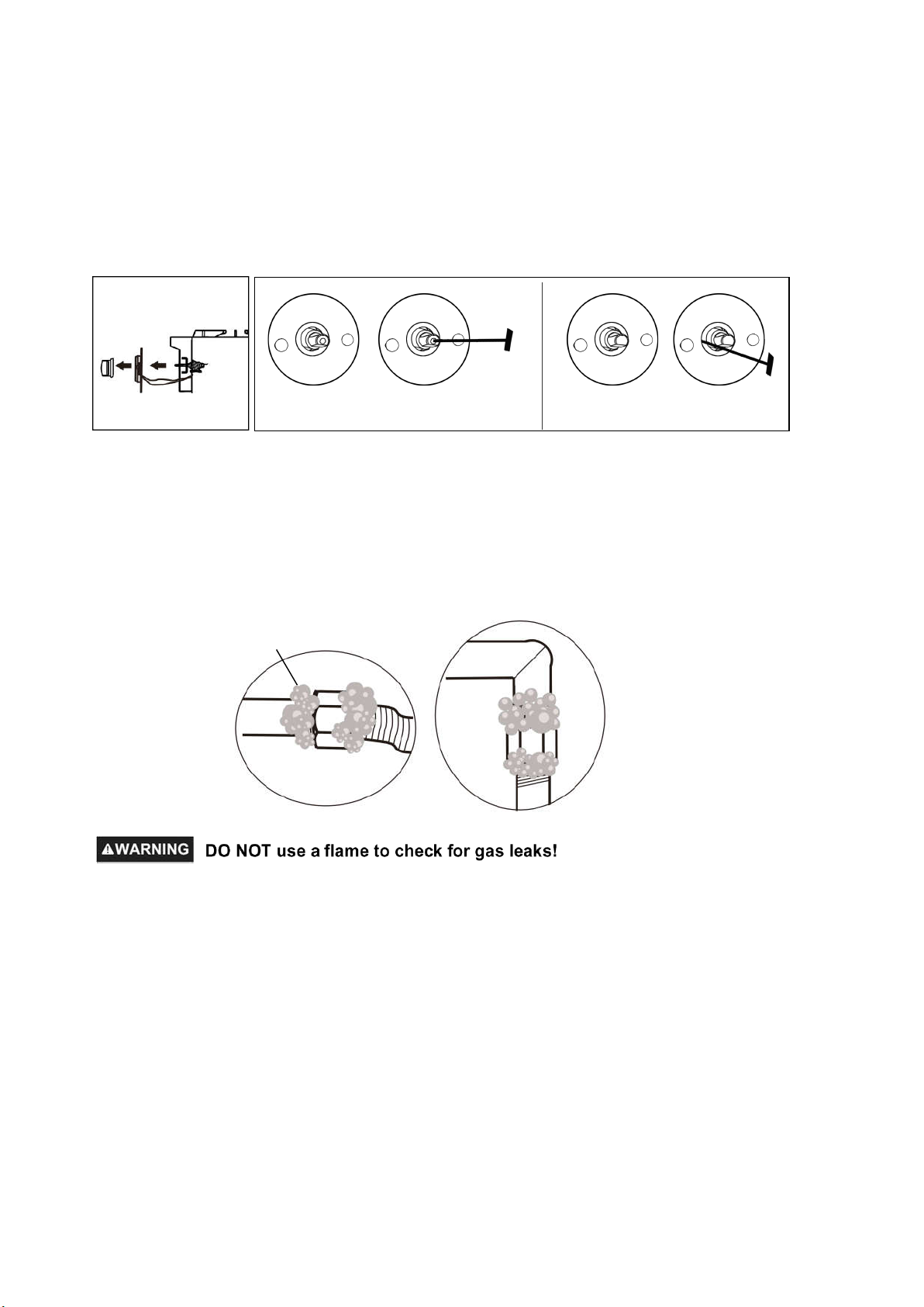
STEP 3: Gas Valve
a. Remove control knobs.
b. Using a flat screwdriver, adjust main burner bypass jets toward to 1/4 circle for LP until the flame
is normal. For 9,000btu and 15,000btu burners, please refer to fig.1, which is in the center of valve
axis. For 20,000btu burners, please refer to fig.2, which is in the left side of valve axis.
STEP 4: Reconnect Gas and Electrical Supply
Leak testing of the rangetop shall be conducted according to the installation instructions provided
with the rangetop.
Before operating the rangetop after the gas conversion, always check for leaks with a soapy water
solution or other acceptable method in at gas connections installed between the gas inlet pipe of the
rangetop, gas regulator, and the manual shut-off valve.
STEP 5: Installation of New Rating Label
Record the model and serial number on the LP / Propane Rating serial plate provided in this kit.
The information can be obtained from the existing Rating / Serial plate. Place the new plate as
close as possible to the existing Rating / Serial plate on the rangetop.
fig.1 fig.2
Use soapy solutions to check for leakage on all joints.

20
Gas Supply Connection
All connections to the gas piping must be wrench-tightened. Do not overtighten or allow pipes to
turn when tightening.
When all connections have been made, check that all rangetop controls are in the “OFF” position
and turn on the main gas supply valve.
If a flexible metal connector is being used, verify it is not kinked, then attach the gas supply line to
the regulator on the rangetop. Open the valve and check for leaks by placing a liquid detergent
solution onto all gas connections. Bubbles around connections indicate a gas leak. If a leak
appears, close the shut-off valve and adjust connections.
Leak testing of the appliance shall be conducted according to the manufacture’s instructions. Use
some soap water (50% water and 50% soap) or a leak detector at all joints and connections to
check for leaks in the system. Do not use a flame to check for gas leaks.
The appliance must be isolated from the building’s gas supply piping system by closing its
individual manual shut-off valve during any pressure testing of the gas supply piping system at test
pressure equal to or less than 0.5 psi (3.5kPa).
Getting Started
Before you start cooking, please take the following steps.
• Remove the exterior and interior packing.
• Remove the protective film on steel and aluminum parts.
• Clean the rangetop thoroughly with hot water and a mild detergent. Rinse and dry with a soft
cloth to remove any residual oil and grease left over from the manufacturing process.
• Check that surface burner components are assembled correctly.
Cooktop Operation
The burner design combines all burner
parts in one assembly. The burner cap must
be seated horizontally on the burner. Refer
to the illustration.
Other manuals for Alfa Qualita FCTGS5751-30
1
This manual suits for next models
2
Table of contents
Other Forno Hob manuals


