manuals.online logo
Brands
  1. Home
  2. •
  3. Brands
  4. •
  5. AGA
  6. •
  7. Hob
  8. •
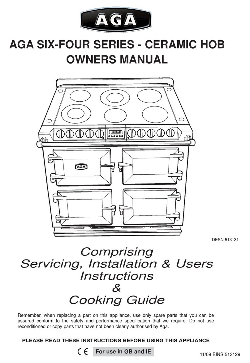
  9. AGA Six Four Series User manual

AGA Six Four Series User manual

AGA
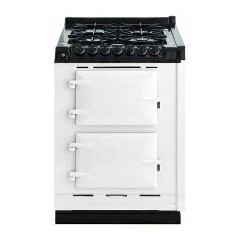
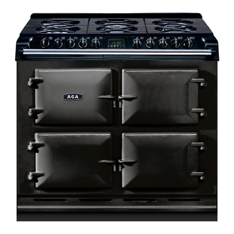
AGA Six Four Series
Six Four Series
(with gas hob)
(with gas hob)
assembly instructions
for models supplied in modular format
s.t 6.04
sixfourassbly1gas
This guide must be read in conjunction with the normal product installation instructions
AGA
AGA Six Four series (Gas Hob)
Six Four series (Gas Hob)
---
--- assembly instructions for modular models
assembly instructions for modular models
Installation Requirements
Floor :-
To ease handling the product may be delivered in five separate cartons, the heaviest
of which is 86kg. This requires the cooker to be assembled on site in accordance with
these instructions.
The floor should be level and strong enough to carry the total weight of 245kg. There
are levelling adjustments fitted to the Aga to compensate for minor variations.
This product requires a safety chain and stability bracket to be fitted.
Clearances:-
Refer to diagram below
Where the Aga is to be ‘slot’ fitted, a gap of 3mm is recommended each side, to allow
the product to slide in easy. See dimension ’B’
Dimension ‘A’ 60mm, is the clearance to be provided against any side wall which
extends above the level of the hob, to allow for protruding utensil handles.
Dimension ‘C’ 650mm is the minimum clearance required to any surface immediately
above the hob. but, if a cooker hood is to be installed, the clearance must be increased
to 800mm. We recommend the Aga CH900 hood which has been specifically designed
for this product.
2
AGA
AGA Six Four series (Gas Hob)
Six Four series (Gas Hob)
---
--- assembly instructions for modular models
assembly instructions for modular models
Gas Supply:-
The gas supply pipe should not be less than 15mm diameter. A fixing kit is supplied
with the product suitable for the relevant gas, i.e. LPG or Natural. This includes a 48”
length bayonet hose & adaptor, stability bracket & chain.
The gas fittings must not protrude further than 45 mm from the wall, therefore the spe-
cial straight bayonet adaptor supplied should be used, in conjunction with a ‘flat’ wall
bracket plate, rather than using an elbow. The gas supply must terminate within the
shaded area shown below.
This product requires the safety chain and stability brack-
et supplied to be fitted as shown
3
Electrical Supply:-
The Six-Four requires connection to a single phase 30 amp supply, using a 6mm2cable.
Alternatively, a 3 phase & neutral supply may be used with 2.5mm2 cable, noting that in
this case the load is as follows L1 2.0 kW, L2 2.3 kW, L3 3.0 kW
Conversion between 1 phase / 3 phase is easily accomplished as shown below
An appropriate electrical isolator must be fitted within 2 metres of the Aga, but not sited
immediately above it. In the case of an existing supply, it should be confirmed that both
the isolator and the cable back to the distribution board are both rated to deliver 30 amp
An excess length/loop of cable should be provided at the rear to permit connection into
the Aga, into the position shown overleaf.
Cable entry is at the Right-hand side of the rear panel at high level.
AGA
AGA Six Four series (Gas Hob)
Six Four series (Gas Hob)
---
--- assembly instructions for modular models
assembly instructions for modular models
1 phase connections
3 phase connections
4
Assembly procedure:-
1. Check that all 5 cartons are present and carefully unpack the contents.
Remove side panels from oven assembly, but leave rear panel in place to provide a
lifting point.
Lift oven assembly off of its pallet.
AGA
AGA Six Four series (Gas Hob)
Six Four series (Gas Hob)
---
--- assembly instructions for modular models
assembly instructions for modular models 5
Remove rear panel (7 screws) From the rear of the Front plate. Remove
four outer screws but leave the two centre
ones loosely in place.
Lift front-plate onto main oven chassis, engaging the two centre screws into the slotted
holes. Ensure that the front-plate drops down into the baseplate and that the apertures
line up to the ovens. The seals should be slightly compressed.
Using an extended length screwdriver passing
between the ovens, tighten the centre two
screws, then work evenly around the outer ones,
ensuring that the ovens seal against front-plate.
AGA
AGA Six Four series (Gas Hob)
Six Four series (Gas Hob)
---
--- assembly instructions for modular models
assembly instructions for modular models 6
Fasten the hotplate chassis down to
the the main assembly. 4 screws.
Identify and unwrap the three oven thermostat capillaries. These will be found labelled
and tied to the rear of the hotplate chassis.
To avoid confusion, work with one at a time.
Lower left
Thread each capillary through into its respective oven and into its retaining clip.
Lower right
AGA
AGA Six Four series (Gas Hob)
Six Four series (Gas Hob)
---
--- assembly instructions for modular models
assembly instructions for modular models 7
Top right
Plug in the two multi-way plugs. They
are biased and will only fit into their cor-
rect sockets.
Refit rear panel.
An electrical safety test must now be
performed.
Confirm that the household electrical
supply is of correct polarity.
Select 500v on a megger tester and
connect the leads on to the appliance
connections.
Depress the test button and record
results. Meter should read infinity.
Any inconclusive results should be
investigated and rectified.
AGA
AGA Six Four series (Gas Hob)
Six Four series (Gas Hob)
---
--- assembly instructions for modular models
assembly instructions for modular models 8
Connect mains supply onto terminals as shown page 3
Refit side panels. Note that they drop down into the base then slide forward into posi-
tion.
Connect flexible gas hose.
Slot splashback into its sockets
Cooker may now be rolled into its final position and gas hose plugged in.
Carry out gas tightness test.
Using the four levelling screws, turn clockwise to raise the cooker off of its wheels
and to obtain the final level adjustment.
Fit the hotplates into position and secure with the corner stay-nuts and buttons.
Remember to locate the gaskets and to connect the earthwires from the castings.
Fit the burners and pan supports as shown in the installation instructions
AGA
AGA Six Four series (Gas Hob)
Six Four series (Gas Hob)
---
--- assembly instructions for modular models
assembly instructions for modular models 9
Complete installation by fitting the doors and test the correct functioning of ovens, con-
trols and hotplate burners etc.
Demonstrate correct operation to owner.
Check that each oven ‘floor’ is
pushed up tight and seals against
the front-plate.
Adjustment can be gained by slack-
ening the screw located at the rear
of the plate.

Other manuals for Six Four Series

2

Other AGA Hob manuals

AGA TC3 Instruction Manual

AGA

AGA TC3 Instruction Manual

AGA Six Four Series User manual

AGA

AGA Six Four Series User manual

AGA DC3 Instruction Manual

AGA

AGA DC3 Instruction Manual

AGA TC/DC Use and care manual

AGA

AGA TC/DC Use and care manual

AGA 60 User manual

AGA

AGA 60 User manual

AGA Companion User manual

AGA

AGA Companion User manual

AGA 7 Series Instruction Manual

AGA

AGA 7 Series Instruction Manual

AGA ELECTRIC HOB UNIT User manual

AGA

AGA ELECTRIC HOB UNIT User manual

AGA 60 Instruction Manual

AGA

AGA 60 Instruction Manual

AGA LPRT 517725 Instruction Manual

AGA

AGA LPRT 517725 Instruction Manual

AGA FFD User manual

AGA

AGA FFD User manual

AGA eR7 Series User manual

AGA

AGA eR7 Series User manual

AGA Masterchef II Ceramic User manual

AGA

AGA Masterchef II Ceramic User manual

AGA AG1M251730 User manual

AGA

AGA AG1M251730 User manual

AGA CITY60 CONTEMPORARY User manual

AGA

AGA CITY60 CONTEMPORARY User manual

AGA TC MODULE (FFD)(with Gas Hob) User manual

AGA

AGA TC MODULE (FFD)(with Gas Hob) User manual

AGA 4-oven User manual

AGA

AGA 4-oven User manual

AGA SIX-FOUR Series User manual

AGA

AGA SIX-FOUR Series User manual

AGA FFD User manual

AGA

AGA FFD User manual

Popular Hob manuals by other brands

Gaggenau VI 270134 use and care manual

Gaggenau

Gaggenau VI 270134 use and care manual

SCHOLTES TV 641 GH operating instructions

SCHOLTES

SCHOLTES TV 641 GH operating instructions

Electrolux LIT60336C user manual

Electrolux

Electrolux LIT60336C user manual

John Lewis JLBIGGH605 instruction manual

John Lewis

John Lewis JLBIGGH605 instruction manual

Gaggenau CE291 Series user manual

Gaggenau

Gaggenau CE291 Series user manual

ROSIERES RES8D instruction manual

ROSIERES

ROSIERES RES8D instruction manual

AEG 66331 K-MN user manual

AEG

AEG 66331 K-MN user manual

AEG Electrolux FM 6520 K-AN user manual

AEG Electrolux

AEG Electrolux FM 6520 K-AN user manual

Leonard LES6001F user manual

Leonard

Leonard LES6001F user manual

Euromaid CH32 Installation & operating instruction

Euromaid

Euromaid CH32 Installation & operating instruction

KitchenAid 2C-1R-2SR -1AUX Instructions for use

KitchenAid

KitchenAid 2C-1R-2SR -1AUX Instructions for use

Tisira TCT90 user manual

Tisira

Tisira TCT90 user manual

Taurus GI3EB manual

Taurus

Taurus GI3EB manual

AEG HC412000 user manual

AEG

AEG HC412000 user manual

NEFF T16BT71N manual

NEFF

NEFF T16BT71N manual

AEG HE634400XB user manual

AEG

AEG HE634400XB user manual

ETNA T009V manual

ETNA

ETNA T009V manual

BORETTI MLIH84 instructions

BORETTI

BORETTI MLIH84 instructions

manuals.online logo
manuals.online logoBrands
  • About & Mission
  • Contact us
  • Privacy Policy
  • Terms and Conditions

Copyright 2025 Manuals.Online. All Rights Reserved.