Forte 450 Series User manual

1
1
2
3
4
5
6
7
8
9
10
450 Series 30 & 36 Inch
Built-In Bottom Freezer Refrigerator
Installation Manual
F16BFRESC450PR
F16BFRESC450SS
F20BFRESC450PR
F20BFRESC450SS
11
12
13
14

2
Table of Contents
Symbols and Their Meanings ...........................................................................................................................................4
Installation Place.............................................................................................................................................................7
Tool list...........................................................................................................................................................................10
ALTERNATIVES FOR INSTALLATION......................................................................................................................................11
PREPARATION FOR INSTALLATION ......................................................................................................................................12
Cabin Dimensions...........................................................................................................................................................12
Location of the Electrical Wiring....................................................................................................................................13
Location of the Water System........................................................................................................................................14
Production dimension …… ........................................................................................................................................... 16
Unpacking ......................................................................................................................................................................26
Removing Connectors on the rearWall..........................................................................................................................28
Removing Mounting Parts in the Freezer Compartment...............................................................................................29
Removing the FRZ Crisper..............................................................................................................................................30
Removing the FRZ Door .................................................................................................................................................31
Removing the Lower Vent Hole Assembly.....................................................................................................................32
Removing the Upper Vent Hole Part..............................................................................................................................33
PRE-INSTALLATION.............................................................................................................................................................34
Mounting the Anti-Tip Brackets.....................................................................................................................................34
Alternative anti-tip method...........................................................................................................................................37
Preparing the Water Hose and the Power Plug.............................................................................................................38
INSTALLATION TO THE CABIN ............................................................................................................................................39
Taking the Refrigerator from the Wooden Pallet ..........................................................................................................39
Placing the refrigerator into the cabin...........................................................................................................................40
Adjusting the height of the refrigerator in the cabin.....................................................................................................43
Adjusting the refrigerator according to the cabin flange...............................................................................................44
Screwing the side brackets ............................................................................................................................................47
Screwing the upper bracket...........................................................................................................................................48
INSTALLING THE CABIN BOTTOM ......................................................................................................................................49
Water connection ..........................................................................................................................................................49
Attaching the upper vent hole part ...............................................................................................................................51
Attaching the lower vent hole assembly........................................................................................................................52
Attaching the decorative parts ......................................................................................................................................53
FURNITURE DOOR PREPARATION......................................................................................................................................54
Choosing the Door Thickness.........................................................................................................................................54

Confidential
3
Removing the Mechanism Covers..................................................................................................................................56
Removing the Panel-Adjustment Mechanisms on the Refrigerator..............................................................................57
Preparing Furniture Door...............................................................................................................................................59
Preparing the Fridge Furniture Door .............................................................................................................................60
Installing the Fridge Furniture Door...............................................................................................................................68
Installing the Freezer Furniture Door.............................................................................................................................74
HINGE ADJUSTMENT..........................................................................................................................................................80
Adjusting the hardness of the hinges ............................................................................................................................80
CHANGING THE DIRECTION OF THE FF DOOR ...................................................................................................................81
Removing the FF clad door ............................................................................................................................................81
Removing and preparing the Fridge Inner Door............................................................................................................84
Replacing the hinges......................................................................................................................................................86
Installing the FF PU Door................................................................................................................................................90
4
Symbols and Their Meanings
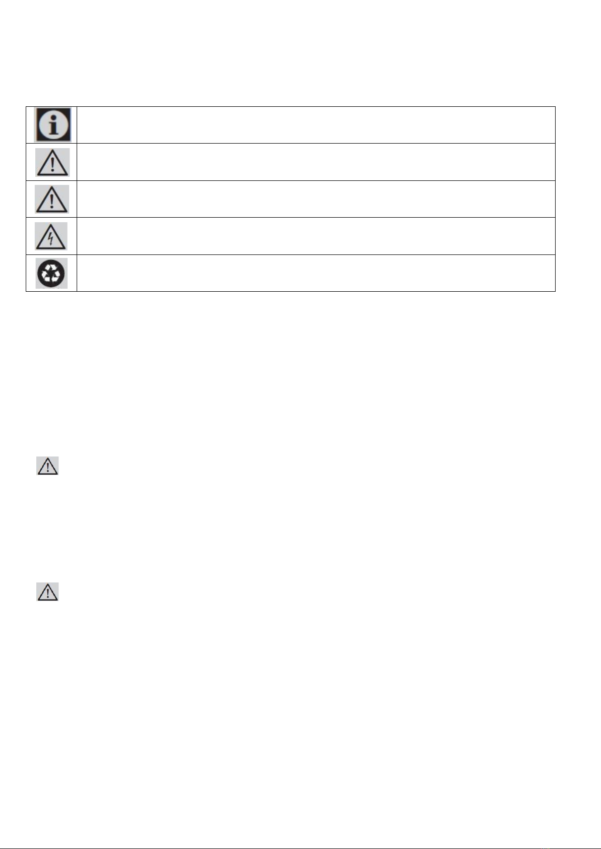
Symbols used in the installation manual are as follows.
Important information or useful usage tips
WARNING: Conditions that may damage the product or its operating functions
ATTENTION: Conditions containing serious injury risk
Conditions containing electric shock risk
Packaging materials of the product have been manufactured from recyclable materials in
accordance with our National Environment Regulations.
Disposing the packaging materials
The package has been designed to protect the product during transport.
The packaging materials used for the product do not harm the nature during disposal and
they need to be recycled.
All plastic packaging materials, bags etc. must be disposed safely and kept out of the reach of children.
Please return the packaging to your dealer.
WARNING:
This installation manual has been prepared to help installation teams. The User Manual provided with the product
must also be taken into consideration.
You may get seriously injured and your product may get damaged if you ignore the warnings given in this manual.
Please read the following carefully.
WARNING:
R600a Refrigerant
This product contains R600a isobutane refrigerant, which is a very eco-friendly natural gas. However, it is also
flammable. Please follow the warnings given below:
•If the product has been transported horizontally, you must wait for 4 hours minimum before plugging itin.
•The following instructions must be followed during installation:
•Dimensions of the installation area must besuitable.
•Dimensions, features and position of the object used to support and fix the product to this area must be
suitable.

Confidential
5
•Minimum clearances between product parts and surrounding structures must besuitable.
•Minimum dimensions and proper organization of ventilation holes must beobserved.
•The product must be connected to the mains power,
and corresponding connections of other components must be suitable.
•The product must be disconnectable from the power supply afterinstallation.
•The socket or fuse must be accessible to de-energize theproduct.
•Extension cables or ungrounded (two-terminal) adapters must not beused.
ATTENTION:
You must wear gloves and eye protectors when installing the product.
You must also take measures against high noise levels when drilling the floor or using a drill.
ATTENTION:
Make sure that your product is suitable for your local mains.
ATTENTION:
The product must be installed by a qualified technician according to the installation instructions.
WARNING:
The product may tip over since it is quite heavy. For this reason, precautions must be taken against tipping over.
The doors of the product must be kept closed until it reaches the destination and it must be transported
in accordance with the installation instructions.

6
Climate class
Product weight:
Load bearing capacity of the doors
Climate range
Ambient temperature of the room
This appliance has been designed to
be used in certain climate ranges
(ambient temperatures). It must not
be used out of this range.
SN
N
ST
T
Between +50oF (10oC) and +90oF (32oC)
Between +60oF (16oC) and +90oF
(32oC)
Between +60oF (16oC) and +110oF (38oC)
Between +60oF (16oC) and +120oF (43oC)
Category
F16BFRESC450PR
F20BFRESC450PR
FFD20ESC450PR
Product weight
361Ibs (164kg)
373Ibs (169kg)
355IIbs (161kg)
Max load
F16BFRESC450PR
F20BFRESC450PR
FFD20ESC450PR
Fridge door
55Ibs (25kg)
55Ibs (25kg)
22Ibs (10kg)
Freezer door
22Ibs (10kg)
22Ibs (10kg)
22Ibs (10kg)
22Lbs
(10kg)
22Lbs
(10kg)
FFD20ESC450PR
TRF-76BINFIA
TRF-91BINFIA
F16BFRESC450PR
F20BFRESC450PR

7
Installation Place
You must follow the instructions below:
•The floor on which the product will be installed must be capable of bearing 1,200 pounds (544 kg)minimum.
•Kitchen floor and the bottom of the product must be at the same level. Otherwise, problems may occur with
the air suction of the product.
•There must be no objects preventing the installation of the product at the back and on the side walls of the
product's installation place.
•The power socket must be at the correct place.
•Dimensions of the furniture where the product will be installed must be in strict conformity with the
dimensions given in the manual.
•Do not install the product with the fridge and the freezer are adherent next to each other. Otherwise,
condensation and damage may occur in the product. (Please see "Dual Cabin Installation" for detailed
information)
•Flatness of the floor where the product will be installed must be checked with a Bubble Level Tool.
•Installation area must not be subjected to direct sunlight and it must be away from heat sources, ovens,
radiators etc.
•The ambient temperature must be between 55°F (13°C) and 110°F (43°C). Otherwise,
•function errors may arise when the product is running.
•If it is not possible to avoid installing the product near a heat source, the minimum clearances given below must
be maintained between the product and the said source:
•11/4" (3 cm) from electric hobs orovens 1 1/4”
•12" (30 cm) from gas or fuel operated hobs orovens
Please observe the following rules:
•The power socket or fuse must be easily accessible in case of an emergency;
it must not be hidden behind the product.
•Plug or cable must not touch the back surface of the product. Otherwise,
it may get damaged due to the vibration of the product.
•Do not connect the plugs of other appliances behind this product.
If the humidity level is high where the product is used, corrosion may be seen
on the outer surface of the product.
Keep the installation room dry and well-cleaned to avoid corrosion.

Confidential
8
To avoid the risk of electric shock:
•Connect the plug to a grounded 3-pin socket.
•Do not remove the ground terminal of the plug.
•Do not use adapters.
•Do not use extension cables.
ATTENTION:
Failure to follow these instructions may result in death, fire or electric shock. Connecting the grounding conductor of
the equipment to an improper place may lead to electric shock. Please have the grounding checked by a qualified
electrician or service technician if you have any doubt about the proper grounding of the product.
Installation, repair and other procedures performed by unqualified persons may cause danger. Before installing the
appliance, make sure that the voltage, load and circuit current parameters on the data plate are in compliance with
the power mains in your house.
The appliance is provided with a NEMA 5-15 P plug and a 3-pin power cable which is in the UL list and ready to be
connected to a 120 V, 60 Hz power supply. Fuse is 15 A. The appliance must be connected to a 3-pin socket. The plug
must be installed only by a licensed electrician.
If the electrical wiring or the electric power supply of the house needs alteration, the necessary procedures must be
performed by a qualified electrician.
ATTENTION:
Do not install your refrigerator:
•In open areas
•In environments where water is dripping
•In environments where temperature is lower than 55° F(0°C)
Furniture:
Make sure that the furniture where you will install the appliance has been safely mounted in your kitchen.
Your furniture must be connected to the floor and the wall properly and with suitable connections.
For the best installation, clearances between the furniture and the product must be in compliance
with the values specified in the installation instructions.
Side walls must be free of clearances and their surfaces must be flat.
Minimum thickness of the side walls must be 5/8" (16 mm).
Minimum thickness of the doors to be attached to the product must be ¾" (19 mm) .

9
ATTENTION:
There is a stainless steel door and stainless kick plate option. Please consult the authorized service.
Ventilation:
Vent holes where the air enters and exits the unit must not be blocked or obstructed. In addition, you must
periodically clean the dust and dirt that accumulate on these holes in time.
Electrical Connection:
•Never use an extension cable.
•The power socket must definitely be grounded and checked by an authorizedperson.
•Location of the electrical wiring must comply with the dimensions specified in themanual.
ATTENTION:
RISK OF ELECTRIC SHOCK
Electrical grounding is necessary. This appliance is equipped with a three-pin plug
to protect you against possible electric shocks.
•Do not remove the round grounding terminal from theplug.
•Do not use two-pin groundingadapters.
•Do not use extension cables to energize theproduct.
ATTENTION:
Do not connect the grounding cable to the gas pipe. Please have the grounding checked by a qualified electrician if
you are not sure about the grounding of the product. Do not install a fuse on the neutral line or grounding circuit.
WARNING:
Please wait for 3-6 hour before energizing the product to protect it against possible damages. This way, the
refrigerant and the lubricants in the system get balanced.
Water Connection
•Pressure of the mains water must be in compliance with the values specified in themanual.
•Location of the water system must comply with the dimensions specified in themanual.
IMPORTANT INFORMATION:
Bypass is recommended for the water filtering system if a reverse osmosis system is used.
10
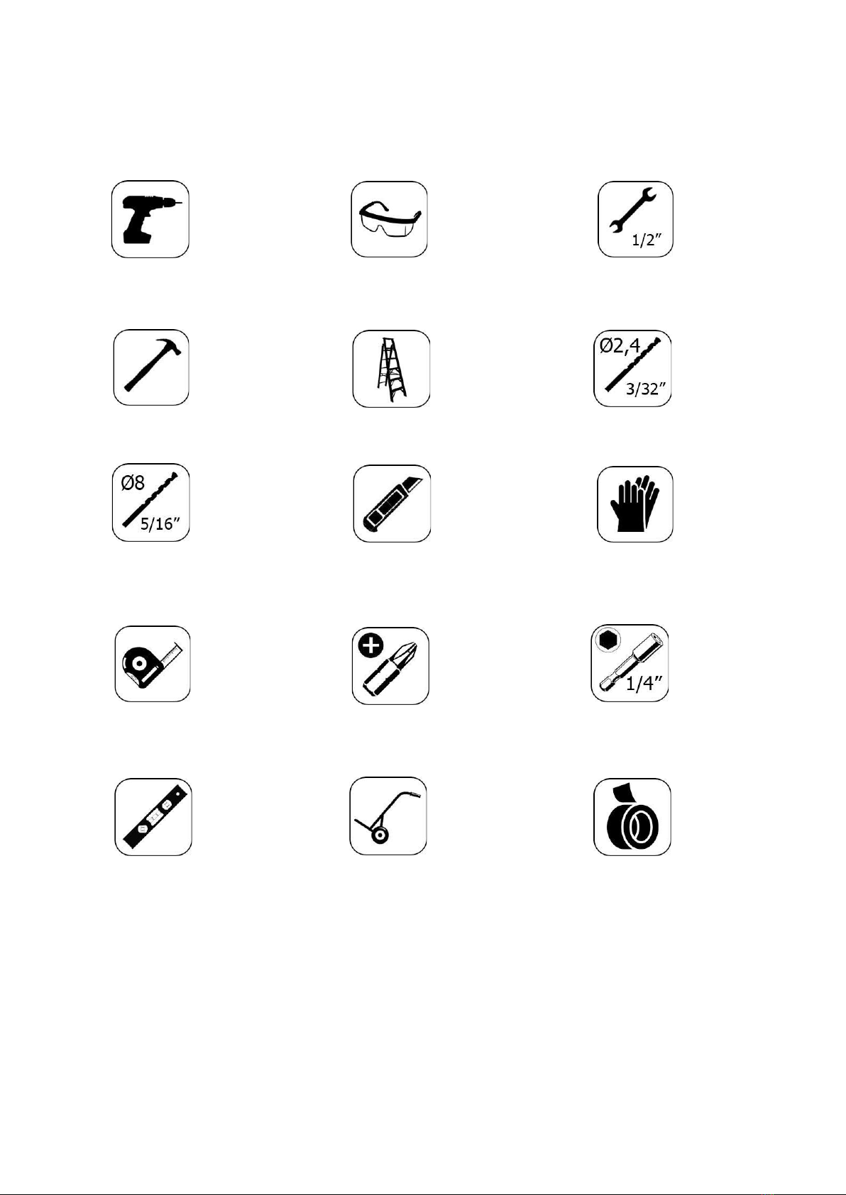
TOOL LIST
Tools to be used when installing the product are as follows:
Cordless
Drill
Safety
Goggles ½"
Wrench
Hammer Ladder Ø2.4
Drill bit
Ø8.0
Drill bit Box
Cutter
Safety
Gloves
Tape
measure
Star bit ¼"
Wrench Flat
Bubble
Level
Tool
Wheelbarrow Tape
11
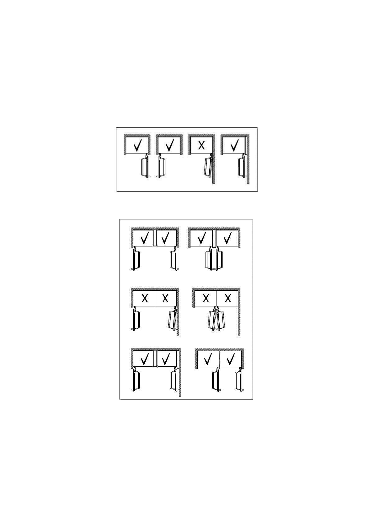
ALTERNATIVES FOR INSTALLATION
The product can be placed in various ways based on the kitchen design. It must be installed at a place where it is
ensured that the door can be opened and closed properly. If the doors cannot be opened 90 degrees at least, you
cannot completely open the drawers inside the product.
•Single cabin placement methods
•Dual cabin placement methods
12
PREPARATION FOR INSTALLATION
The instructions below have been prepared according to Built-in type.
Built-in: The Appliance and Panels fully seat into the gap, and a material that can be their own box is jammed
between the two kitchen cabinets or decorative columns.
This is the most common installation scenario.
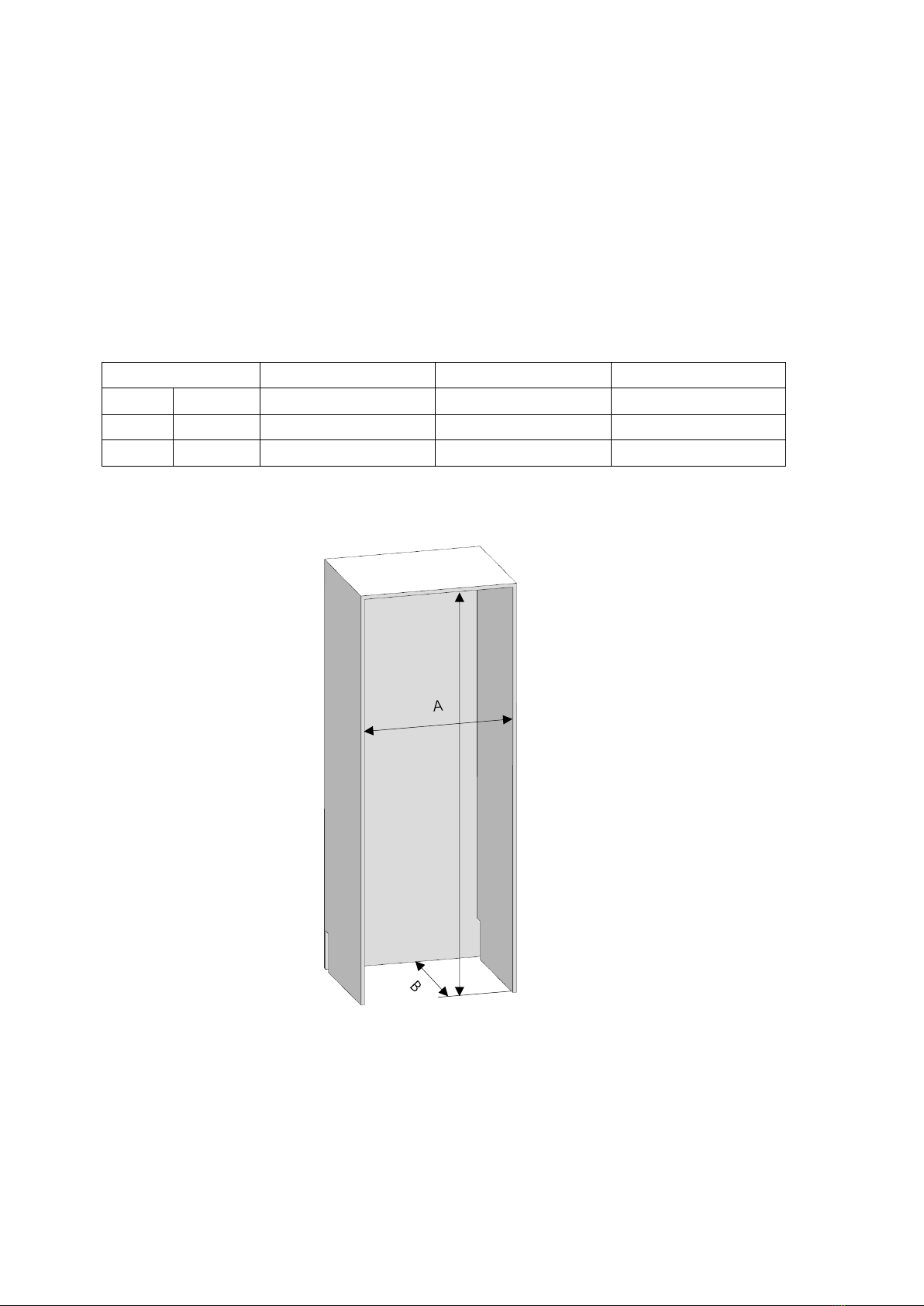
Cabin Dimensions
•Cabin dimensions below must be checked before startingthe installation.
Category
F16BFRESC450PR
F20BFRESC450PR
FFD20ESC450PR
A
width
30" (762mm)
36" (914mm)
36" (914mm)
B
depth
25" (635mm)
25" (635mm)
25" (635mm)
C
height
84" (2134mm)
84" (2134mm)
84" (2134mm)
C
13
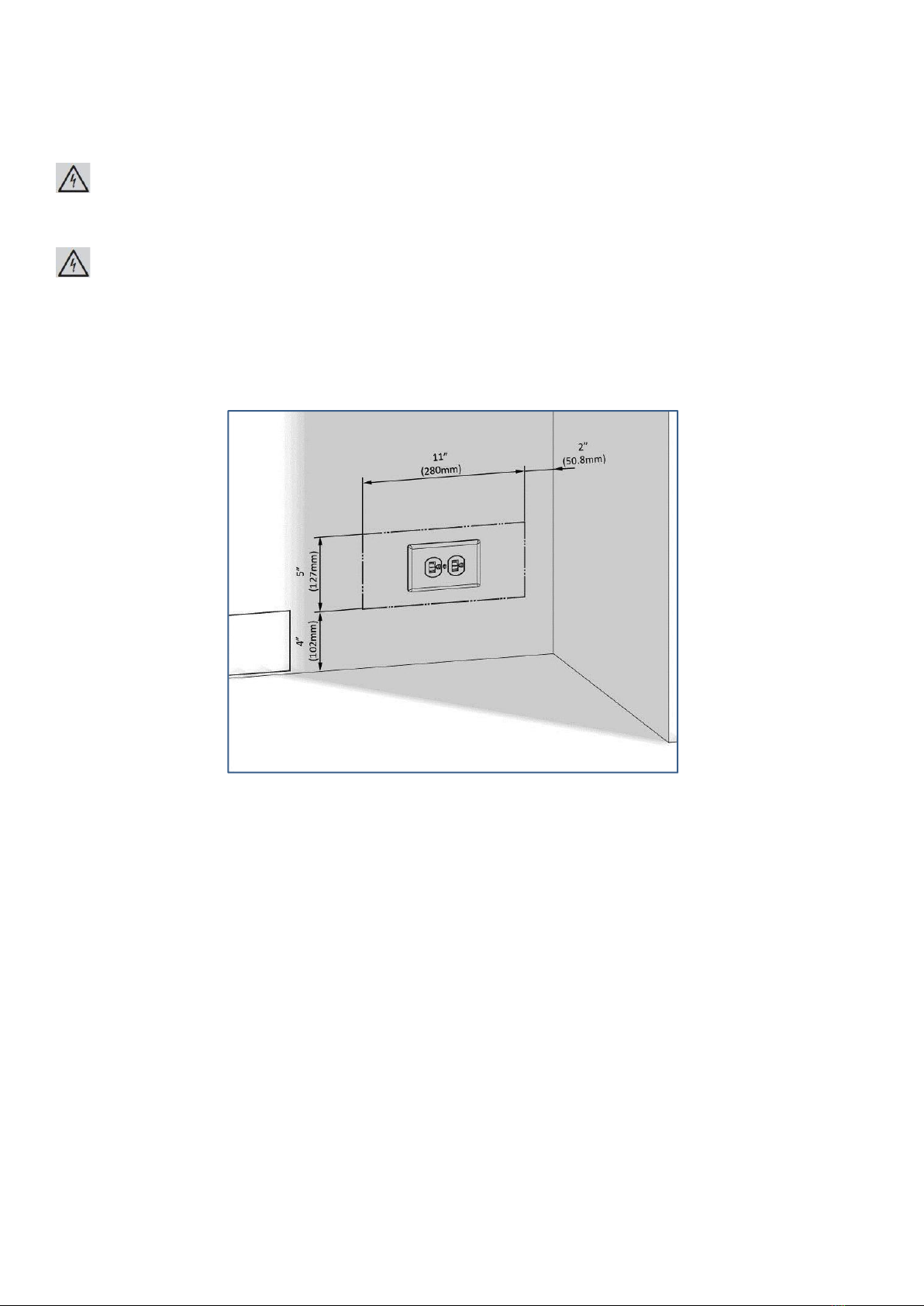
Location of the Electrical Wiring
Location of the electrical wiring must be within the range given below.
ATTENTION:
Do not use extension cables or two-pin adaptors and do not remove the ground terminal of the grounding cable.
ATTENTION:
A qualified electrician must ensure that the poles of the socket are connected correctly.
Verify that the grounding of the socket is correct.
14
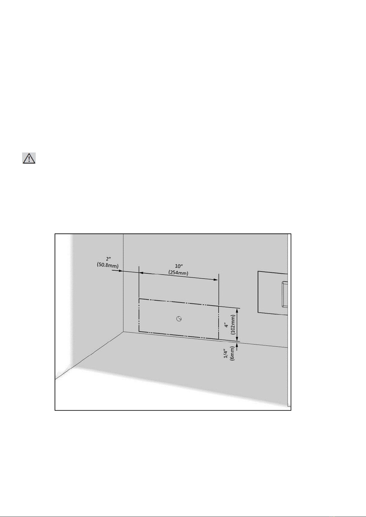
Location of the Water System
The water connected to the water mains must be potable.
Location of the water system must be within the range given below.
Water system of the refrigerator must be connected to the water mains system in the house.
The user must be able to switch it on/off with the valve when necessary.
Objects that might pierce the water hoses or cause them to twist must not be present
where the water line is installed.
Pressure of the water system must be between 25-80 psi (1.7-5.5 Bar).
If the water pressure exceeds 80 psi, install a pressure limiting device or water impact protector to the inlet valve.
Never install the product or operate the appliance if it is possible for the water pressure to exceed 120 psi.
WARNING:
Make sure that there is no water leakage when making the water connections. Otherwise,
there will be water on the floor and the furniture will get damaged.
You will need a hose with a minimum length of 60" (1.5 meters) and a diameter of ¼"
for water connections of the product during installation.
A connector that has a thread with an external diameter of ¼ must be used to connect the hose end to the product.
Before completing the installation, make sure that water flows and there is no water leakage.

15
WARNING:
•Flatness of the floor where the product will be installed must be checked with a Bubble LevelTool.
•Uprightness of the furniture flanges must be checked with a Bubble Level Tool.
•If the flatness and uprightness of the product is not proper, problems may arise with theinstallation.

16
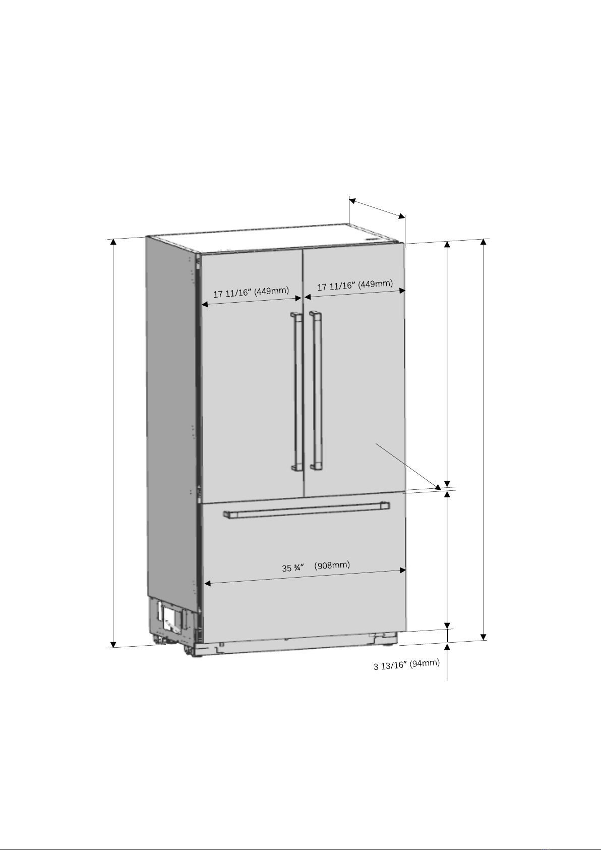
PRODUCT DIMENSION
Category
F16BFRESC450PR
F20BFRESC450PR
A
29 3/4” (756mm)
35 3/4” (908mm)
51 1/16”(1297mm)
28 11/16”(729mm)
83 9/16”(2123mm)
3
without panel : 23 5/16”(592mm)
with panel : 24 ¼” (616mm)
83 9/16”(2123)
17
51 1/16”(1297mm)
28 11/16”(729mm)
83 9/16”(2123mm)
without panel :23 5/16”(592mm)
with panel : 24 ¼” (616mm)
83 9/16”(2123)
Gap : 1/8”(3mm)
FFD20ESC450PR
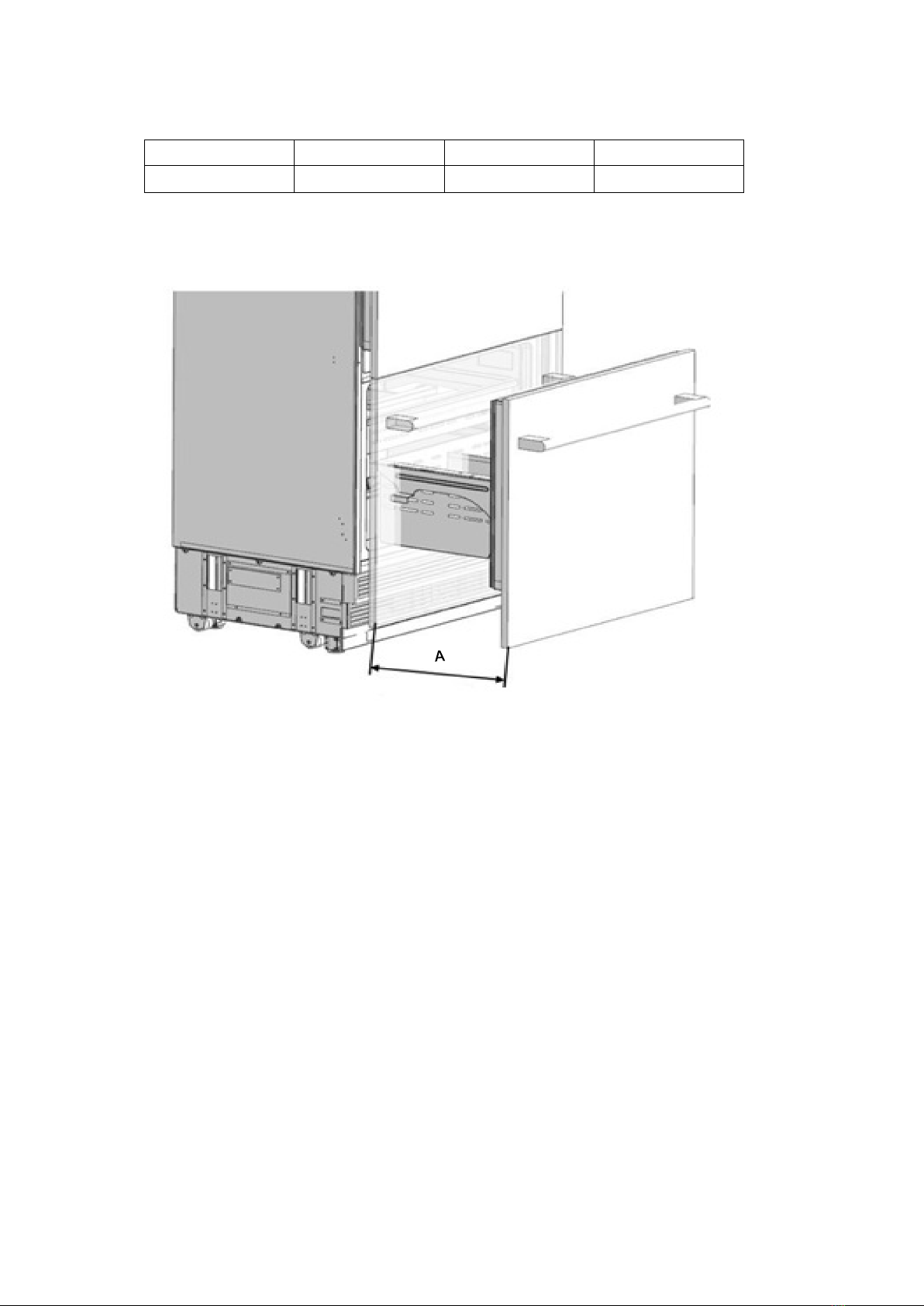
18
Category
F20BFRESC450PR
F20BFRESC450PR
FFD20ESC450PR
A
15 9/32" (388mm)
15 9/32" (388mm)
15 9/32" (388mm)

19
Category
F16BFRESC450PR
F20BFRESC450PR
A
32 7/16”(824mm)
38 7/16”(976mm)
B
29 3/4“(756mm)
35 3/4“(908mm)
C
55 1/32”(1398mm)
61”(1550mm)
21 27/32”(555mm)
2 11/16
”
(68mm)
90°Door swing
Minimum to wall
3/8”(10mm)
90°
B
C
A

20
Category
F16BFRESC450PR
F20BFRESC450PR
A
443/8”(1127mm)
54 3/4”(1391mm)
B
29 3/4“(756mm)
35 3/4“(908mm)
C
14 5/8”(371mm)
19”(483mm)
D
52 11/16”(1338mm)
57 11/16”(1466mm)
115°Door swing
115°
A
C
D
B
Other manuals for 450 Series
1
This manual suits for next models
4
Table of contents
Other Forte Refrigerator manuals

Forte
Forte F21UFLESSS User manual

Forte
Forte F12BFRES450R User manual

Forte
Forte 450 Series User manual

Forte
Forte F12BFRES450SS User manual

Forte
Forte F16SBS250SS User manual

Forte
Forte F10TFRESSS User manual

Forte
Forte F18TFRESWW User manual

Forte
Forte FFD18ES250SS User manual

Forte
Forte F15TFRESWW User manual

Forte
Forte F14ARESWW User manual


