FRANCO UCP-fly Instruction manual

INSTRUCTION MANUAL FOR USE
AND MAINTENANCE
UCP-fly
COOLER
HUMIDIFIER
E N G L I S H
Before installing or running the unit,
it is mandatory to carefully read and consult this manual.
Manual version: 01-000/2010 Franco srl –Via Nazionale, 80 12010 Cervasca (CN), Italy

FRANCO srl Manual of use and maintenance UCP-fly
2
INDEX
INDEX ......................................................................................................................................2
1 - INTRODUCTION.................................................................................................................3
1.1 General warnings............................................................................................................3
1.2 Instructions for proper disposal of the product................................................................3
1.3 Conventions used in this manual....................................................................................4
1.4 Instruction manual conservation.....................................................................................4
1.5 Recipients.......................................................................................................................5
1.6 Glossary and pictograms................................................................................................5
1.7 Applications ....................................................................................................................9
1.8 Versions..........................................................................................................................9
1.9 Identification and data label of the unit ...........................................................................9
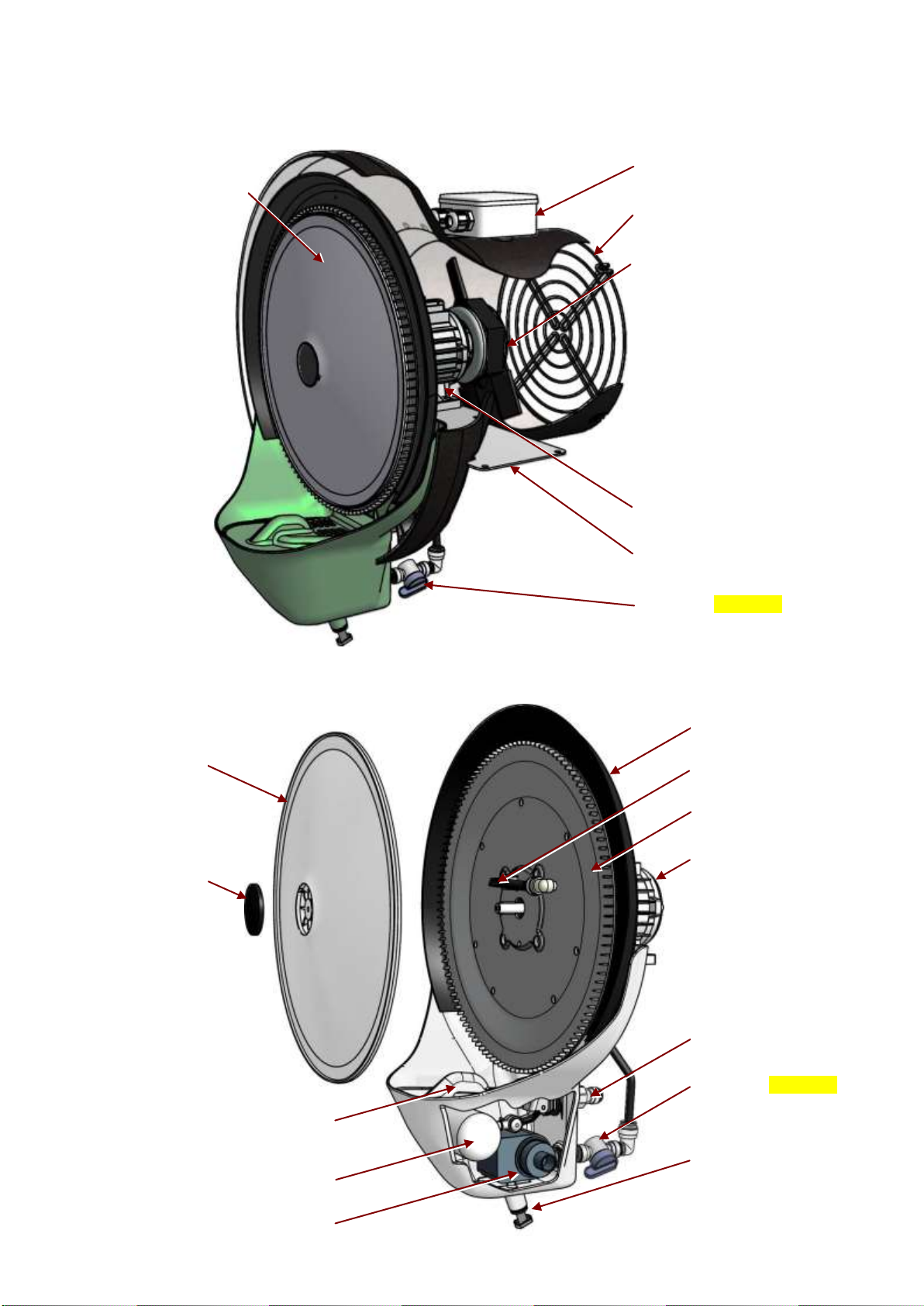
1.10 Parts description......................................................................................................... 10
1.11 Transport and handling...............................................................................................11
1.12 Warranty.....................................................................................................................11
1.13 Manufacturer’s identification data ...............................................................................11
1.14 Declarations................................................................................................................11
1.15 Declaration of conformity............................................................................................12
2 - INSTALLATION................................................................................................................ 13
2.1 Before installing............................................................................................................ 13
2.2 Positioning....................................................................................................................13
2.3 Electrical connection.....................................................................................................14
2.4 Hydraulic connection .................................................................................................... 14
3 - OPERATION..................................................................................................................... 14
3.1 Getting started..............................................................................................................14
3.2 First start.......................................................................................................................14
3.3 Starting ......................................................................................................................... 15
3.4 Setting...........................................................................................................................15
3.5 Water drain...................................................................................................................15
4 - MAINTENANCE................................................................................................................ 15
4.1 Cleaning the disk .......................................................................................................... 15
4.2 Cleaning the tank..........................................................................................................15
4.3 Changing the float.........................................................................................................16
4.4 Changing the pump ...................................................................................................... 16
4.5 Replacing the nozzle ....................................................................................................16
4.6 Replacing the spinning disk..........................................................................................17
4.7 Replacing the fan..........................................................................................................18
4.8 Accessories .................................................................................................................. 18
5 –TECHNICAL SPECIFICATIONS...................................................................................... 19
5.1 Technical data ..............................................................................................................19
5.2 Wiring diagram..............................................................................................................20
5.3 Spare parts...................................................................................................................21
6 - PROBLEMS AND SOLUTIONS ....................................................................................... 23

FRANCO srl Manual of use and maintenance UCP-fly
3
1 - INTRODUCTION
1.1 General warnings
This device must be used only for the functions it was intended for: "Adiabatic Cooler –Humidifier”. Any other
use has to be considered improper and dangerous. Franco s.r.l. cannot be held liable for any damages caused
by improper, incorrect or unreasonable use, or if the device is used in systems that do not comply with safety
regulations.
- Check the integrity of the device at the opening of the package, paying particular attention to the presence of
damages or deformations of the plastic parts that can lead to breakage and/or malfunction during use. In such
cases do not connect the machine to the main. Carry out these checks before each use.
- Before connecting the unit, make sure that the data shown on the device’s plate matches that of your electricity
distribution network. The data label is located on the side of the device (par.1.9).
- Respect the safety standards set for the electrical equipment and in particular:
oFollow the installation and operation instructions concerning the use of the equipment.
oDo not place objects on the humidifier.
oEnsure that children and/or unable subjects cannot use the device without proper supervision.
oDo not touch the humidifier during operation or until the complete stop of the disk.
oNever immerse the device into water or any other liquid. In case of the device becoming wet,
immediately turn off the electricity by lowering the switch on the electrical panel of your system and
disconnect the power before touching the device.
oDo not insert objects inside the tank as the device may be damaged irreparably.
oDo not use accessories, spare parts and/or components which are not provided or supplied by the
manufacturer.
oAvoid touching the appliance with wet and/or humid hands.
oDo not pull the power cord nor expose it to risk of severing.
oDo not expose the unit to weather (rain, sun, etc...).
oIn case of failure or malfunction, switch off immediately and disconnect the power. Do not try to open or
tamper the device: contact the technical service provided by Franco s.r.l.
oDo not try to fill and/or empty the tank during operation.
1.2 Instructions for proper disposal of the product
In compliance with the European Directive 2002/96/EC.
At the end of its useful life the product must not be disposed of as waste.
The device can be taken to special recycling centers provided by local authorities, or at retailers that provide this
service. Disposing the product in separate parts avoids possible negative consequence to the environment and
to human health, which would both be the result of an inappropriate disposal, and allows the retrieval of
materials which results in significant savings in energy and resources. As a reminder of the obligation to dispose
electrical equipment separately, the product will be marked with the crossed-out wheeled bin.
Fig. 1.1

FRANCO srl Manual of use and maintenance UCP-fly
4
1.3 Conventions used in this manual
The Manual is divided into autonomous chapters, each of which is addressed to a specific operator (installer,
operator and maintenance operator), who have the skills needed to operate the machinery safely.
The chapter order follows the temporal logic of the machine life.
To facilitate the immediate understanding of the text, terms, abbreviations and pictograms, whose meaning is
shown below, are used throughout the manual.
The Instruction Manual consists of a cover, an index and a series of chapters (sections).
The home page lists the machine and model identification data, the revision of the instruction manual, and
finally, a picture of the described machine, drawn in order to facilitate the reader to identify the machine and its
use.
ABBREVIAZIONI
Ch. = Chapter
Par. = Paragraph
P. = Page
Fig. = Figure
Tab. = Table
UNITS OF MEASURE
The units of measure used in this manual are those provided by the International System (SI).
1.4 Instruction manual conservation
The instruction manual must be carefully stored and must follow and match the device in all the cases of change
of ownership incurred during the life span of the machine itself.
The manual must be handled with care, with clean hands and placed on clean surfaces. Do not remove, tear or
arbitrarily modify any part.
The manual must be stored in a secure environment, protected from moisture and heat, and near the device to
which it refers. The manufacturer, if requested by the User, may provide additional copies of the machine’s
instruction manual.
UPDATING THE MANUAL
The Manufacturer reserves the right to modify the design or specifications of the machine as part of its policy of
improving and enabling them to comply with the statutory or other requirements or standards applicable in any
territory in which its goods are sold, without notifying the Customer and without updating the manuals given to
the user. Moreover, in case of changes (previously agreed between the Customer and the manufacturer) to the
machine installed, which entails a change in one or more chapters of the Instruction manual, the manufacturer
will be responsible for sending the modified chapters (including the new revision) to the User.
The User is responsible, following the directions accompanying the updated documentation, for replacing all the
copies owned, the old chapters with the new ones, the home page, and the index with the new updated version.
The manufacturer shall be responsible for the descriptions included in this manual; in case of any inconsistency
detected in a translated version of the manual (English version), the reader must refer back to the original Italian
version of the manual and, if needed, contact the sales department, who will make necessary changes.

FRANCO srl Manual of use and maintenance UCP-fly
5
1.5 Recipients
The manual is addressed to: the installer, the operator, and the qualified personnel entitled to the maintenance
of the device.
EXPOSED PERSON:
refers to any person wholly or partially exposed to a danger zone;
OPERATOR:
refers to those persons responsible for installing, operating, regulating,
clearing, repairing and moving the machine, and also performing the
maintenance of the device;
QUALIFIED PERSONNEL
QUALIFIED OPERATOR:
refers to the persons who have completed specialization courses and
training, and who have acquired experience in: installing, starting,
operating, maintaining, repairing and transporting the device, or similar
ones
The machine is intended for industrial use (professional and not widespread) for which qualified operators are
needed, in particular, workers who:
Have reached the age of majority;
Are physically and mentally appropriate to perform works which include technical difficulties;
Have been properly educated on the use and maintenance of the machinery;
Have been considered suitable to undertake the assigned job by their employer;
Can understand and interpret the operator’s manual and the safety requirements;
Know the emergency procedures and their implementation;
Possess the ability to operate the specific type of equipment;
Are familiar with the specific applicable rules;
Have understood the operating procedures defined by the manufacturer of the machine.
1.6 Glossary and pictograms
In this section we list the uncommon terms included in the manual. The following table also explains the
abbreviations used and the meaning of the pictograms which indicate the qualification of the operator and the
state of the machine; their use can provide quick and unique information, necessary for the proper use of the
machine under safety conditions.
GLOSSARY (Att. I p. 1.1.1 Dir. 2006/42/CE)
HAZARD
A potential source of injury or damage to health;
DANGER ZONE
Any area within and/or around the machinery in which the
presence of a person constitutes a risk to his/her health and
safety;
EXPOSED PERSON
Any person that finds himself/herself entirely or partially in a
hazardous area;
OPERATOR
The person installing, operating, adjusting, clearing, repairing,
maintaining and moving the machinery;
RISK
A combination of the probability and degree of an injury or damage
to health that can arise in a hazardous situation;
GUARD
The part of the machinery used specifically to provide protection by
means of a physical barrier;
PROTECTION DEVICE
The device (other than a guard) that reduces the risk of an
operation, either alone or in conjunction with a guard;
INTENDED USE
Use of the machinery according to the information provided in the
instruction manual;
REASONABLY FORESEEABLE
MISURE
Use of the machinery in a way not intended in the instruction
manual, which may result from a foreseeable human behavior.

FRANCO srl Manual of use and maintenance UCP-fly
6
OTHER DEFINITIONS:
HUMAN-MACHINE INTERACTION: Any situation in which an operator interacts with the machine in any of
the operational phases at any time of the life of the machine itself;
OPERATOR’S QUALIFICATION:Minimum level of competence that an operator must have in order to
perform the described operation;
NUMBER OF OPERATORS: The appropriate number of operators needed to optimally perform the
described operation, resulting from an accurate analysis made by the
manufacture, and for which the use of a different number of operators
may prevent the occurrence of the expected result or endanger the
safety of the personnel involved;
STATE OF THE MACHINE: The state of the machine includes the operating mode, for example:
running in automatic mode, hold-to-run control (jog), shutdown, etc… the
safety conditions on the machine such as included protectors, excluded
protectors, emergency shutdown, isolation from energy sources, etc…
RESIDUAL RISK: Risks that remain, despite the inherent safe design measures,
safeguarding and complementary protective measures.
SAFETY COMPONENT: Component:
- designed to fulfill a safety function;
- the failure and/or malfunctioning of which endangers the safety of
persons (such as a lifter; a fixed, moving or adjustable protector; an
electrical, electronic, optical, pneumatic or hydraulic device which
interlocks a protector; etc…).

FRANCO srl Manual of use and maintenance UCP-fly
7
PICTOGRAMS REGARDING THE OPERATOR’S QUALIFICATION
Symbol
Description
Generic worker: operator lacking of specific competences, capable of performing only simple tasks
under the control of qualified technicians.
Lifting and handling vehicles driver: operator qualified for the use of vehicles used in lifting and
handling materials and machines (carefully following the manufacturer’s instructions), in accordance
with the user country’s laws.
Mechanical maintenance operator: qualified technician, able to operate the machine under normal
conditions, to run it with the hold-to-run control (JOG) with disabled protections, and to intervene on
the mechanical parts in order to make the necessary adjustments, maintenances and repairs.
Typically this operator is not qualified to work on electrical systems while the device is connected to
the main.
Electrical maintenance operator: qualified technician, able to operate the machine under normal
conditions, to run it with the hold-to-run control (JOG) with disabled protections, and enabled to any
kind of operation of electrical adjustment, maintenance and repair. This operator is qualified to work
on electrical systems while the device is connected to the main.
Manufacturer’s technician: qualified technician provided by the manufacturer to carry out complex or
particular operations or any other operation agreed with the user. The skills are, as the case may be,
mechanical and/or electrical and/or electronic and/or software.
PICTOGRAMS REGARDING THE STATE OF THE DEVICE
Pictograms in a square/rectangle provide information.
Symbol
State of the device
Device OFF: with electric and pneumatic power disconnected.
Machine in motion: with automatic function, movable protections closed and relative interlocking
devices activated, and fixed protections closed.
Device ON: in standby and ready to start by functional consent activation (eg. switchboard
consent), movable protections closed with relative safety device included, and fixed protections
closed.

FRANCO srl Manual of use and maintenance UCP-fly
8
PICTOGRAMS REGARDING SAFETY
Pictograms contained in a triangle indicate DANGER.
Pictograms contained in a circle impose PROHIBITION / OBLIGATION.
Pictogram
Denomination
Hazardous voltage.
Entanglement.
Dragging.
General danger.
Do not remove safety devices.
Prohibition of cleaning, oiling, greasing, repairing or adjusting by hand when the device is in motion.
Obligation to remove power before starting works or repairs.
Protective gloves required.
Safety footwear required.
Safety helmet required.

FRANCO srl Manual of use and maintenance UCP-fly
9
1.7 Applications
In the industrial field, the machine is installed in places where it is necessary to maintain a certain humidity
level, for example in fruits and vegetable refrigerating rooms, in aging warehouses, in the paper and tobacco
industries, and in textile companies.
In agriculture the machine is used to humidify greenhouses and mushroom farms, and for disinfectant
treatments.
In animal husbandry the machine is used to cool or nebulize disinfectant or other solutions in the environment.
The casing is made in PE, the screws are in stainless steel, and the remaining parts of the humidifier are made
in PA PC and ABS.
The UCP-fly combines the power of the humidification and the ease of installation.
The water pressure required is the same as in the water supply network (between 2 and 4 atm).
This device must be used only for the functions for which it was intended
and designed: "Adiabatic Cooler –Humidifier”.
Any other use has to be considered improper and dangerous.
1.8 Versions
The adiabatic cooler/humidifier UCP-fly is available in the following versions:
3108400 Version UCPfly H15 with air flow of 750 m³/h 230V 50Hz
3108500 Version UCPfly H15 with air flow of 750 m³/h 230V 60Hz
3108000 Version UCPfly H20 with air flow of 100m³/h 230V 50Hz
3108200 Version UCPfly H20 with air flow of 1.100m³/h 230V 60Hz
3108100 Version UCPfly H25 with air flow of 1.800m³/h 230V 50Hz
3108300 Version UCPfly H25 with air flow of 1.800m³/h 230V 60Hz
1.9 Identification and data label of the unit
Each machine is identified by the CE plate on which the reference data of the device is inscribed indelibly.
In any communication, either with the manufacturer or with the customer service, always cite these references.
Fig.1.2
The label plate positioning may vary from one device to another.

FRANCO srl Manual of use and maintenance UCP-fly
10
1.10 Parts description
Fig.1.3
Constituent parts of the centrifugal atomizer
Fig.1.4
Spinning disk
Spinning disk cap
Tank lid
Rear shelter
Float valve
Recirculation pump
Nozzle
Motor
Water supply connection,
fast connection 3/8”
Water flow regulation
valve
Fast connection drain
hole ⅜” with cap.
Fixed disk
Electric connections box
Safety grill
Anchorage bracket
Fan
Electric motor
Water flow regulation valve
Centrifugal atomizer

FRANCO srl Manual of use and maintenance UCP-fly
11
1.11 Transport and handling
The machine has been properly packed before being put into sturdy carton boxes.
Carefully open the package to prevent damages to the components of the device.
Verify the integrity of the machine by controlling that there are no visible damaged parts.
Do not dispose the packaging elements in the environment; they must be disposed in suitable waste
collection points.
The UCP-fly can be lifted and hung using suitable brackets.
WARNING!
Before moving the device:
a. stop the machine,
b. disconnect the electrical supply,
c. interrupt the water supply.
To lift the machine, use a suitable lifting device (consult the weights table).
Lift the machine slowly, being careful not to drop it and moving the straps according to the centre of mass.
1.12 Warranty
This device is guaranteed for 12 months from the date of manufacture for all failures attributed to a proven
manufacturing or material defect.
The guarantee does not cover all the parts damaged by transport, improper maintenance, negligence, inability to
use, improper use, tampering by unauthorized personnel and by any other cause not dependent from the
company Franco s.r.l. from Cervasca (CN), Italy. During the warranty period, the company Franco s.r.l.
undertakes to replace or repair free of charge those parts which result faulty from the origin.
The intervention must be made at Franco s.r.l. with transport borne by the user.
1.13 Manufacturer’s identification data
Manufacturer
FRANCO S.r.l.
Registered office –Administrative headquarters
VIA NAZIONALE, 80 - 12010 CERVASCA (CN) - ITALY
Contacts
Tel.: (0039) 0171 - 61.16.63
Fax: (0039) 0171 - 61.23.37
Email: [email protected]
Web: www.francosrl.com
1.14 Declarations
The machine is built in accordance with the EC directives that are relevant and applicable at the time of its the
market entry.
The machine is not among those mentioned in the Att. IV of the Directive 2006/42/CE.

FRANCO srl Manual of use and maintenance UCP-fly
12
1.15 Declaration of conformity
(Att. IIa DIR. 2006/42/CE)
THE MANUFACTURER
FRANCO S.r.l.
Company
Via Nazionale, 80 12010 CN
Address Postal code Province
Cervasca Italy
City Country
DECLARES THAT THE MACHINE
Cooler / Humidifier UCPfly H15 / UCPfly H20 / UCPfly H25
Description Model
3108000 / 3108100 / 3108200 / 3108300 / 3108400 / 3108500 2018
Series/Registration number Year of construction.
UCP - fly Cooler / Humidifier
Commercial denomination
Humidification and/or cooling of environments
Intended use
Meets the following essential requirements:
RESS from 1.1 to 1.7
Complies with the EU directives:
Directive 2006/42/CE - Directive 2006/95/CE - Directive 2004/108/CE
Referring to harmonized norms: EN 120100-1; EN 12100-2;EN 60204-1
AND AUTHORIZES
Marco Fantino
Name
Via Nazionale 80 12010 CN
Address Postal code Province
Cervasca Italia
City Country
TO COMPILE THE TECHNICAL FILE ON HIS BEHALF
Place and date of the document
The manufacturer
Cervasca, 10/05/2010
Firma
Function
Administrator
D.C.: DC N-001/310001

FRANCO srl Manual of use and maintenance UCP-fly
13
2 - INSTALLATION
2.1 Before installing
In order to start the UCP humidifier, it is necessary to comply with the following requirements:
Connection to the electric power supply with voltage and frequency suitable for the machine and
with grounding and safety devices;
Connection to water supply (pressure required: between 2 and 4 atm);
The operating temperature must be between 1°C and 40°C.
The unit must be supplied with drinking water, or water having a low fixed residue, or treated
water. The water quality affects the unit maintenance, the frequency of the servicing operations
and the correct functioning of the humidifier.
We suggest suggested to provide the unit with temporized discharging system to drain the
water tank, as a bleed-off valve, in order to keep the unit in good working conditions.
The installation must meet the safety requirements provided by local regulation in force.
Follow the regulations of the UNI 8884 standard “Requirements and treatment of water cooling
and humidification system.” conductivity <100 μS/cm and total hardness <5° fH (50 ppm CaCO3).
Make sure that all the connections necessary to operate the equipment have been properly prepared.
2.2 Positioning
The UCP humidifier / cooler must be installed horizontally, hanging off the ground, with the non-
atomized water tank facing down. Use the suitable brackets to hang the machine and to hold it in
the correct operating position with an appropriate sealing system (the distance between holes is
shown in Figure 2.1).
Fig.2.1
Holes positioning for hanging
Example of installation on the ceiling with chains.
The machine must be installed in horizontal position.
The positioning of the UCP-fly must be done by maintaining the minimum recommended
distance that allows the correct operation of the machine and to perform maintenance when
needed. Choose the most suitable position for the humidification and cooling of the
environment according to the type of installation adopted.
In order to prevent fog condensation on walls, maintain a minimum distance of 1m from the
ceiling and the walls, while as for the front wall, the distance has to be calculated based on the
UCP-fly model chosen and the amount of water atomized.
The machine installation must meet the safety distance in
accordance with the DIN UI EN ISO 13857/2008 norm. The machine must
be placed at least at 2.5 meters above the ground level.
1m
OK
NO

FRANCO srl Manual of use and maintenance UCP-fly
14
2.3 Electrical connection
The installation requires a humidistat or an ON/OFF thermostat controlling the power of the
machine; it is also possible to use, as an alternative, an ON/OFF switch, in this case the start
and stop of the machine must be done manually.
The choice, however, does not affect the installation procedure described below.
Electrical connections must be performed by specialized, experienced and trained
technicians, in accordance with the current legislation.
Ensure that the electricity supply specifications correspond to those indicated in the
in this manual.
It is obligatory that the device is grounded using an efficient ground line.
The installation should provide a device for machine disconnection from the electric supply, furthermore, a safety
fuse of 2.5 A (delayed motor start-up type) must be installed.
2.4 Hydraulic connection
The installation of the humidifier requires the connection to the water supply and drainage piping
lines at the designated sites (Fig. 1.4 –Fast connection for “rilsan” 3/8” tube - Exhaust hole with
fast connection ⅜”).
Hard rilsan pipes must be used for drainage, while as for supply a fast connection is ready for
“rilsan” 3/8” pipes.
3 - OPERATION
3.1 Getting started
Before operating the humidifier, verify that:
1. All connections, both electrical and hydraulic, are made according to the instructions contained in this
manual;
2. The humidifier is free and clean;
3. The water supply tap is open.
3.2 First start
- Check the correct air flow direction (Fig. 3.1);
- Check the spinning direction of the centrifuge (Fig. 3.1);
- Make sure all wires are regularly placed and not caught or pulled by any object;
- Ensure that the water connections are correct;
- Open the water supply tap and make sure that there are no leaks along the load circuit;
Fig. 3.1
Air
Flow
Spinning direction
of the disk
WARNING!
The humidifier’s disk can
spin up to 3200 rpm!

FRANCO srl Manual of use and maintenance UCP-fly
15
Adjust the water flow with the proper flow regulator in order to obtain a nebulization without
droplets dragged by the spinning disk.
Warning: an excessive quantity of water increase the size of the droplets
The pump must not operate without water.
The temperature of the liquid used must not exceed 35°C.
3.3 Starting
The machine starts automatically when the electrical power is switched on
The pump circulates the water bringing it to the rotating disk that, spinning at 2.820 rpm, atomize the water
through the use of small “teeth”.
3.4 Setting
It is possible to vary the amount of atomized water adjusting the valve that regulates the spinning disk’s water
supply (Fig. 3.1).
The machine can nebulize from 15 to 55 lt/h (the quantity of atomized water affects the quality of the fog).
3.5 Water drain
The machine comes with a cap placed on the bottom of the storage tank. It is possible to empty the tank by
removing the cap.
To do this, act on the stopping ring pressing it gently (the operation can be facilitated by using a no. 10 spanner)
and remove the cap.
4 - MAINTENANCE
Before undertaking any maintenance,
disconnect the device from the electricity and water supply!
Periodically check that the amount of water reaching the slinger is correct, if necessary adjust the flow regulator.
Keep the disks, the tank and the internal components clean, and prevent dirt the accumulation on the lid.
4.1 Cleaning the disk
Keep the disk clean to avoid the formation of calcareous deposits or accumulation of dirt, which could cause an
increase in vibration or coarse nebulization.
To clean the rotating disk, simply use a soft damp cloth and a non-toxic and solvent free detergent, and be
careful to rub without excessive pressure.
Do not use solvents.
The fixed disk should be cleaned with a small brush with stiff bristles, rub the teeth, being careful not to damage
them.
Any eventual limescale can be removed with muriatic acid diluted with water.
4.2 Cleaning the tank
Periodically clean the water tank.
To access it, unscrew the two screws on the lid and pull gently, grasping the grip.
To ease the cleaning, it is possible to remove the float’s ball and the pump.
To remove the ball it is necessary to unscrew the plastic arm of the float (Fig. 4.1).
To remove the pump it is necessary to operate while holding with a no. 13 spanner the stop ring that blocks the
pump and pull gently the pump up to complete removal.
Once all these operations have been completed, it is possible to clean the interior of the tank with a cloth or a
sponge, rubbing gently on the walls. Do not use solvents.
It is necessary to periodically check the functioning and the cleanliness of the pump and the float.
Each 2-3 months clean the internal parts of the pump with warm water.

FRANCO srl Manual of use and maintenance UCP-fly
16
4.3 Changing the float
Disconnect the water supply by releasing the spreader pipe from the fast connection 3/8”.
Remove the two screws from the lid using a crosshead or “Phillips” screwdriver. Remove the cover pulling it,
grabbing the grip between the thumb and the forefinger.
After unscrewing the ½” connection with the 3/8” tube fast connection, unscrew the plastic ring nut indicated in
Fig. 4.3 and, consequently, remove the body of the float.
Place the new float and repeat the sequence in the reverse order, so that the water level inside the tank covers
the pump completely.
Fig. 4.1 Fig.4.3
4.4 Changing the pump
Remove the two cover screws using a cross or “Phillips” screwdriver. Remove the lid by pulling it, grabbing the
grip between thumb and forefinger. Unscrew the plastic arm of the float as shown in Fig. 4.1. Operate holding
the stop ring that blocks he pump with a no. 13 spanner and pull the pump gently up to complete removal.
Remove the nylon pawl from the pump supply and fit it onto the new pump. Repeat the sequence backward,
being careful to reposition the float so that the water level inside the tank covers the pump completely.
4.5 Replacing the nozzle
After removing the spinning disk (par. 4.5), remove the nozzle unscrewing n.2 - 2,9x9,5 screws.
Push the grey ring on the elbow connection (page 22 - item 22) and pull out the nozzle.
To place the new nozzle, repeat the same sequence in the reverse order.
Fast connection 3/8”

FRANCO srl Manual of use and maintenance UCP-fly
17
4.6 Replacing the spinning disk
A.
Remove the cap of the spinning disk. Lever it off
using a flat-heat screwdriver on the specific
groove.
B.
With a nut driver (pic no. 7) remove the M4
screw that fixes the disk to the motor shaft. Then
remove also the washer.
C.
Insert the M6x40 screw (provided with the
machine) into the central hole of the disk.
SCREW M6x40
SCREW M4
with washer
3~5mm
7

FRANCO srl Manual of use and maintenance UCP-fly
18
D.
Using a screwdriver (pic no.10) tighten the
screw. By tightening the screw into the hole the
disk will be pulled out effortlessly.
E.
Once the disk is out, unscrew the M6x40 screw
and take it off the hole.
F.
Grease the motor shaft and insert the new disk. Check that the keys are well aligned, then press on
the centre. Do not beat on it and do not press excessively hard. Place the washer in its place, as well
as the screw M4 and the cap.
The distance between the spinning disk and the fixed disk must be about 4mm. If it is not, adjust it by
adding a spacer or taking a spacer off the motor shaft (item 5 and 6 on the spare parts list –see
paragraph 5.3).
4.7 Replacing the fan
Use a no.7 wrench to remove the 4 screws holding the safety grill. With a no.7 screwdriver unscrew the screw on
the fan impeller. Remove the fan.
Before positioning the new fan, grease the driveshaft, being careful not to misplace the key. Make sure that the
screws are replaced properly, fixing the fan and the safety grill.
4.8 Accessories
A full range of accessories matching your UCP is available, including electronic humidity controls, thermostats,
timing systems for the drainage of the tank (anti-legionella), electric wiring accessories, hydraulic accessories,
air conveying and inhalation channeling pipes.
Request the accessories catalog from your dealer for further details.
10

FRANCO srl Manual of use and maintenance UCP-fly
19
5 –TECHNICAL SPECIFICATIONS
5.1 Technical data
General characteristics
H15
H20
H25
Atomization capacity
lt/h
15 - 25
15 - 25
15 - 25
Electrical supply
1 phase
1 phase
1 phase
Degree of protection IP
IP56
IP56
IP56
Weight
kg
11
11
11
Air flow
m³/h
750
1.100
1.800
Electrical characteristics
Fan-humidifier’s motor
Power
W
380
390
420
Voltage
V
230
230
230
Current
A
1,8
1,9
2,05
Frequency
Hz
50
50
50
Pump’s motor
Power
W
6
6
6
Voltage
V
230
230
230
Frequency
Hz
50
50
50

FRANCO srl Manual of use and maintenance UCP-fly
20
5.2 Wiring diagram
All the wires used must be suitable to carry the current intensity (A) of the motor (par. 5.1).
Le terminal’s screws must be accurately tightened.
Make sure that the electricity supply characteristics are exactly as shown in the table (par. 5.1).
Install a differential magnetic switch upstream of the device.
Protect with a suitable motor overload protection (par 5.1).
Make sure that all connections are stuck on the box, that the box cover is secured and that the
screws are tightened to ensure the necessary level of protection.
Table of contents
Popular Freezer manuals by other brands

Frigidaire
Frigidaire FFC0723DW - 7.2 cu. Ft. Chest Freezer Manuel d’utilisation et d’entretien

ZANKER
ZANKER TT 120 F Instruction book

Electrolux
Electrolux U04454 Installation and use

Frigidaire
Frigidaire FFC7C4AW0 Service data sheet

Huawei
Huawei NetCol8000-C190 user manual

Black & Decker
Black & Decker BCFK356 instruction manual