Frankford AURORA F Specification sheet

AURORA
FRANKFORD UMBRELLAS
NORTH AMERICAN HEADQUARTERS
110 Gaither Drive
Mount Laurel, New Jersey 08054
856-222-4134
Info@frankfordumbrellas.com
frankfordumbrellas.com
OPERATION AND INSTALLATION MANUAL

TABLE OF CONTENTS
GRUB-SCREWS
WIND RATING
GENERAL OPERATION INFORMATION
SIMPLE MAINTENANCE PROCEDURES
FABRIC CARE / LONGEVITY
CASUAL / INTENSIVE FABRIC CARE & CLEANING
GUIDELINES TO CONSIDER BEFORE INSTALLING
ALIGNMENT AND SPIGOT INFORMATION
OPENING AURORA CANTILEVER UMBRELLA
CLOSING AURORA CANTILEVER UMBRELLA
ROTATING THE AURORA CANTILEVER UMBRELLA
INSTALLING THE WIND STABILIZER KIT
IN-GROUND
WOOD DECK SURFACE
CONCRETE/SOLID SURFACE
40G+36G ROUND GALVANIZED PLATE STACK
36Gx2 SQUARE GALVANIZED PLATE STACK
ARU-480 ROLLING BASE
XB-MODULAR CROSS BASE
BASES & MOUNTING INSTALLATION
RESIDENTIAL WARRANTY
WIND RATING & WARRANTIES
COMMERCIAL WARRANTY
BEFORE INSTALLING
GENERAL OPERATION INFORMATION & CARE
FABRIC CARE
UMBRELLA OPERATIONS
AURORA PARTS KEY
01
02
05
06
07
08
09
10
11
12
13
14
17
19
21
23
25
27
29
33
34
15
HARDWARE AND CORRESPONDING BASES03
+C MODULAR CROSS BASE COVER ASSEMBLY31

01
AURORA CANTILEVER UMBRELLAS ARE ENGINEERED TO WITHSTAND
25MPH SUSTAINED WINDS AT AN OPTIMAL 90° ANGLE. THE ADDITION OF
THE WIND STABILIZER KIT INCREASES THIS TOLERANCE BY 5MPH.
DO NOT ATTEMPT TO OPEN OR UTILIZE THE TILT FEATURE AT ANY DEGREE
OF TILT IN WINDY CONDITIONS.
Frankford Umbrellas have been tested successfully in extreme weather and winds, however, we
strongly recommend closing your umbrella when not in use, or in moderate sustained winds.
02
• GRUB-SCREWS ARE IN PLACE TO KEEP THE THREADED HOLES CLEAN AND
FREE FROM DIRT, SAND ETC.
• ONCE YOUR BASE IS IN PLACE, USE THE SUPPLIED ALLEN KEY TO REMOVE
ALL GRUB-SCREWS BEFORE INSTALLING THE UMBRELLA.
BEFORE INSTALLING
• YOU MAY RECEIVE ADDITIONAL MOUNTING HARDWARE WITH YOUR
UMBRELLA THAT IS NOT NEEDED FOR YOUR SPECIFIC MOUNTING
SELECTION.
• DO NOT DISCARD THIS ADDITIONAL MOUNTING HARDWARE IN CASE YOU
DECIDE TO CHANGE YOUR MOUNTING OPTION IN THE FUTURE.
THE FUNCTION OF GRUB-SCREWS ARE ONLY TO PROTECT THE THREADS IN WAREHOUSE STORAGE
AND SHIPPING. ONCE REMOVED, PLEASE DISCARD AND DO NOT LEAVE IN THE BASE. THEY ARE NOT
CORROSION RESISTANT AND WILL RUST IF EXPOSED TO THE ELEMENTS.
WIND RATING
Wind ratings do NOT form part of, nor fall under, any Frankford Umbrellas’ warranties. Wind ratings are
intended as a guide to the relative strength of the umbrellas only and tested at their optimal 90°and non-
tilted positions. Umbrellas with any degree of tilt added should not follow the above wind ratings. Wind can
be extremely variable, depending on the surroundings, elevation, angle of gusts, etc. In any high wind or
sudden extreme weather conditions, all umbrellas should be closed and secured immediately.
Frankford can recommend specific bases and anchoring systems for specific umbrella types. However,
these are only recommended weights, as dierent environments may require dierent base options. Please
contact us for assistance in choosing the proper umbrella base or anchoring system.
In the event Frankford shade products are left open and/or unattended in harsh weather conditions, our
customer service department is here to help you and promptly assist with parts for repairs. Our shade
products oer modular, self-repairable components which allow customers to service the umbrellas to keep
them in perfect working condition.
01

HARDWARE AND CORRESPONDING BASES
MOUNTING HARDWARE FOR BASES, IN-GROUND & SURFACE MOUNTS
You may receive additional mounting hardware with your umbrella that is not needed for specific
mounting selection. Please see the specific mounting installation pages in this manual for your
specific hardware needed, and detailed mounting instructions.
2” X .5” (8MM ALLEN KEY)
1.4” X .5” (8MM ALLEN KEY)
.75” X .5” (8MM ALLEN KEY)
6MM (GUIDE PINS & GRUB-SCREWS)
8MM (MOUNTING HARDWARE)
GUIDE PINS
1:1 SCALE
SCAN THE QR-CODE FOR VIDEO TUTORIAL
SCAN THE QR- CODE FOR THE VIDEO TUTORIAL ON HOW
TO PROPERLY AND EFFICIENTLY STACK THE G-PLATES
USING FRANKFORD GUIDE PINS.
PLEASE BE AWARE OF HARDWARE NEEDED FOR SPECIFIC BASES. NOT ALL HARDWARE WILL WORK WITH ALL BASE
CONFIGURATIONS AND OR MOUNTS.
03 04
TRIPLE GALVANIZED PLATE STACK
• DECK PLATE (SURFACE MOUNTING)
• IG (IN-GROUND MOUNTING)
• ARU-480 ROLLING BASE
DOUBLE GALVANIZED PLATE STACK
• 40+36G
• 36G-SQX2
• XB - CROSS BASE
GRUB-SCREWS ARE IN PLACE TO PROTECT THE THREADED HOLES ON BASES DURING
SHIPPING AND STORAGE. THEY MUST BE REMOVED AND DISCARDED BEFORE THE
INSTALLATION OF ANY UMBRELLA.
• FOR USE WITH TRIPLE PLATE STACK OPTIONS

Your Aurora Cantilever Umbrella is virtually maintenance free. The tips below should aid in the overall
longevity of the product and keep the umbrella working optimally for years to come.
05 06
Congratulations on purchasing your Aurora Cantilever Umbrella. The Aurora is manufactured using
the highest materials and fabrics on the market, and is perfectly designed to give you many years of
enjoyment. The following information will explain how to operate your Aurora Cantilever Umbrella to
ensure trouble free use and ease of operation. Please follow these instructions as they are designed to
assist operation and prolong the life of your umbrella.
SIMPLE MAINTENANCE PROCEDURES
• In coastal or metropolitan environments, frequent washing of the complete unit is beneficial. Particularly
the slider car, slider car guide tracks, and rotating mechanism.
• If you are in a coastal environment, a simple spraying of fresh water to remove any salt water and salt
air deposits on the aluminum that could cause calcium buildup and lead to having to do more intensive
cleanings.
• If extensive calcium buildup or hard water stains are an issue, this can be remedied with 2tbsp of white
vinegar per every quart of boiled fresh water and a soft bristle brush.
• Should the 16 rotating mechanisms stop pin holes become filled with sand or dust etc., lifting your
umbrella up o the Spigot (35) by 1” will allow the dust cover to be lifted and the 16 holes can be
cleaned. This will be a two person operation.
• Spraying silicon spray in the Slider Car and visible pulley wheels will assist operation if required and a
good idea before storing away for a season.
• Fold the acrylic canvas as mentioned in “Closing The Aurora” (Page 12). This will prolong the new look
of the fabric and prevent marking caused by “pinching” in the alloy frame.
• All parts are virtually maintenance free (e.g. aluminum, stainless steel, etc.) However, the above
mentioned care is recommended to increase the overall longevity of the umbrella.
• If the umbrella is not to be used for an extended period of time (winter months), you may remove the
umbrella from the Spigot (35), place in storage and then remove the Spigot as it can be a tripping
hazard.
• The included protective cover should be used when the umbrella will not be operated for an extended
period of time.
GENERAL INFORMATION
Your Aurora Cantilever Umbrella is principally intended for use in low to moderate wind conditions and will
provide you with many hours of protection from sun and light rain. You will get maximum benefit from your
umbrella when you use it in accordance with our instructions and in the weather condition for which it was
designed.
• Do not attempt to open the umbrella in windy conditions. This may cause unwanted stress on the
cranking system as the large umbrella canopy needs to work against the winds.
• Before you begin to open your umbrella, be sure to loosen the Slider Car Knob (26) so that the Slider
Car can travel freely and float along the mast while cranking. Tighten the Slider Car Knob (26) into
position only when the canopy is fully open.
• When you first open your umbrella, the fabric will be sti and you will notice a 1-3” gap between the
Hub Tube (12) and Tube Locator (10). This is normal and as the fabric relaxes this connection will seat
perfectly when fully open.
• DO NOT PUSH THE SLIDER CAR UP INTO ANY DESIRED POSITION BEFORE THE UMBRELLA
CANOPY IS FULLY OPEN. THIS IS TO MAINTAIN TENSION ON THE CABLE SYSTEM TO AVOID ANY
KINKING OR TANGLING, RENDERING THE UMBRELLA INOPERABLE.
• “Flung The Ribs” - When the umbrella is fully closed, the ribs will pass a 180° angle hindering them
from opening from simply cranking. Give the ribs a slight pull out from the hub (“flu”) while cranking.
• Do not leave umbrella open when unattended, particularly in windy conditions. Your Aurora Umbrella
should be closed and securely strapped in strong winds and adverse weather conditions.
• When using the Wind Stabilizer bars, your Aurora should be at it’s 90° locked angle, and Slider Car
Knob (26) tightened. The Wind Stabilizer bars are not to be used when the umbrella is in any degree of
tilt.
• Always secure your umbrella to a Frankford base that is appropriate to the environment in which it is
going to be used.
• Be careful when closing to ensure the canopy does not get caught or “pinched” by the umbrella arms.
• After the umbrella is closed, remove the inward fold by pulling fabric panels “out” from the center
• Once all fabric panels are pulled, fold one over the other towards the front face of the canopy
• Firmly wrap the supplied Velcro fabric strap and place the protective cover over your umbrella
This is particularly important before storing the umbrella away for extended periods of time or if the
umbrella is to be laid horizontally for storage. Damage to the fabric caused by “pinching” is not covered
by the warranty. Follow all manufacturer’s assembly instructions.
• Make sure your Aurora is dry and clean prior to storing away for extended periods of time to prevent
mold from developing on dirt and directly onto the fabric.
• Inspect the installation fitting/base on a regular basis and tighten as necessary.
• Please avoid any modifications to your umbrella, except those made by an authorized Frankford
customer service agent. Unauthorized modifications will void the warranty.

FABRIC CARE
Recacril® Marine Grade Acrylic Fabric Infinity Process is a highly technological finish, providing Recacril with
long lasting protection against mold and mildew, excellent water and oil repellency and protection from
both sun and water. However, the accumulation of dust, pollution particles, foreign organic materials, and
general dirt can damage this protection, shortening the life of the RECacril, so they should be removed. The
most eective method for maintaining Recacril® is to clean the canvas once a month with water using a low-
pressure hose. It is very important that after cleaning with water, the canvas be allowed to completely dry
before rolling or storing your umbrella. If for any reason you have to roll and/or store a wet umbrella, it must
be unrolled and opened as soon as possible to let it dry. In times of continuous rain, it is advisable to keep
the umbrella rolled and stored.
If periodic washing with water is done, in most environments, you should only need to do a more thorough
cleaning every 2-3 years.
CASUAL CARE & CLEANING
• Brush o dust and dirt with a soft brush. NEVER brush with sti brushes since this can damage the fabric
finish.
• Spray the umbrella with clean water. If a hose is used, avoid high pressure.
• Prepare a solution of solvent-free soap in warm water (no more than 100°F) and apply it to the fabric and
stitching.
• Scrub with a soft brush, allowing the solution to penetrate the fabric.
• Rinse with water to remove all traces of soap.
• Let air dry and do not close the umbrella until the canvas is completely dry.
INTENSIVE CARE & CLEANING
Recacril® is highly resistant to the growth of fungus, mold, and mildew. However, these can grow on
embedded dirt. To clean these stains, follow these more intensive cleaning procedures.
• Brush o dust and dirt with a soft brush. NEVER brush with sti brushes as this can damage the fabric
finish.
• Prepare a solution with 10% household bleach, 20% solvent-free neutral detergent (Free & Clear
detergents) and 70% water.
• Apply the solution to the fabric, allowing to remain between 15 and 20 minutes maximum.
• Rinse with clean water several times. Any bleach residues remaining on the canvas, combined with the
sun, could damage the fabric and stitching.
• Let air dry and do not close the umbrella until the canvas is completely dry.
• Repeat the process if necessary.
• DO NOT USE MAJORITY BLEACH BASED DETERGENTS TO CLEAN THE UMBRELLA CANOPY.
07 08
When the umbrella is closed, you’ll notice the weight of the fabric from the panels will tuck and fold in
towards the center hub and becoming pinched between the ribs of the frame. Leaving the fabric in this state
will cause premature wear and tear. Simple friction of constant rubbing and the pinching can cause micro
tears and pinholes on the fabric. This is not detrimental to the integrity of the fabric’s overall state, however
continued neglect over time the tears and pinholes will increase in size and cause a premature replacement
of the canopy.
To prevent this, after closing the umbrella, pull the panel fabric out and fold each panel in an over/over
method before wrapping with the supplied Velcro fabric tie.
FABRIC LONGEVITY

GUIDELINES TO CONSIDER BEFORE INSTALLING
When choosing a location to install your umbrella,
it is important to be aware of the umbrella’s arm
closing height and opening arc. Your umbrella may
connect with a wall, fence or furniture if situated too
close.
OPENING ARC
Be aware of the clearance space required if you
wish to rotate your umbrella. Nearby walls, trees,
fences or a building can limit this umbrella feature.
Positioning your umbrella in a corner can severely
limit your space to rotate.
ROTATIONAL SPACE
Where possible, we recommend the umbrella is
stood up in the desired installation location, and fully
opened before installing the ground anchors. This
is to ensure that the umbrella will fit and that the
installation location is correct. We recommend this is
done in little or no wind.
CHECK THE SPACE
A good rule of thumb when installing an umbrella with full
360° ROTATION, measure for canopy depth fully and rotate
for clearance.
✓
✗✓
✓
Your Aurora Cantilever Umbrella is delivered fully assembled. There are four dierent ways to install your
Aurora Cantilever Umbrella:
1. Installing on a wooden deck using a Deck Plate.
2. Installing on an existing concrete slab or pavers using a Deck Plate.
3. Installing into the ground (i.e. into a lawn, garden or paved patio) using the In-Ground mount.
4. Installing on a free-standing base.
Prior to installing your installation mounts please read the important information below.
Your Aurora Cantilever Umbrella can rotate 360° and be locked in 16 dierent locations. This means that
every 22.5° of rotation there is provision to lock the umbrella. In most situations there will be a preferred
area over which you will predominantly want shade. To ensure you have the ability to shade your preferred
location you must have one of the 22.5° rotation locking holes (Figure A) in line with this position. Please
have a look at the underside of your Spigot (35) to see these 16 locking holes
There is a locking hole in line with each of the 4 Spigot bolt holes in the Spigot plate. There are also three
intermediate holes between each of the Spigot bolt holes and these are marked with an indicator mark on
the top of the Spigot plate.
To point your umbrella in the perfect direction or to have a symmetrical installation (especially when
installing square umbrellas) it is very important to make sure you install the Base Plate or In-Ground mount
square to the direction that you predominantly want the umbrella to point.
ALIGNMENT
Your Aurora Cantilever come with the Spigot (35) already
inserted in the mast of your umbrella. It is a an integral part to
the installation and mounting of your umbrella.
The Spigot is secured within the mast of the Aurora by the
Spigot Locking Pin (36). Pull this button and slide the Spigot
(35) out from the mast.
1. You can mount the spigot to your choice of installation
first, and then secure your Aurora by lifting over and onto the
Spigot (35) until you hear an audible “click” from the Spigot
Locking Pin (36), indicating your umbrella is now secure.
2. You can leave the Spigot (35) inside of your Aurora and
mount the umbrella and Spigot together as a whole to your
choice of installation.
SPIGOT
Figure A
09 10

1. Remove the protective cover by unzipping
from the front. There will be two rods inserted
into the cover, use the rods to lift up and over
towards the back (mast) of the umbrella.
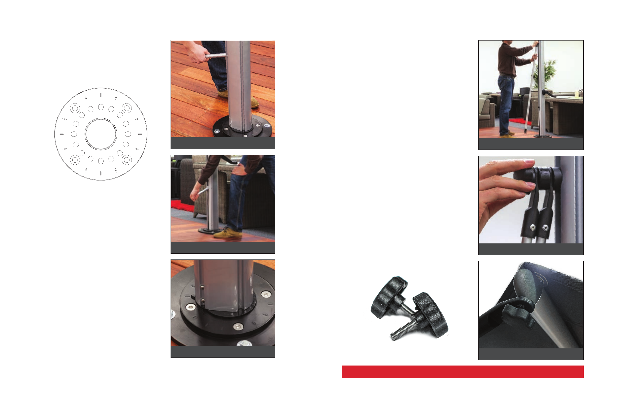
2. Towards the bottom of the mast, move your
attention to the Slider Car/Knob (26), and loosen
the knob. Your canopy will shimmy slightly.
3. Locate the crank handle (28) that is packed with
your umbrella and insert into the indentation on
the mast.
DISCLAIMER: Do not move the slider car into a
desired position until the canopy is 2/3 - fully open.
The cable system must maintain tension through the
opening and closing process.
4. Before cranking, gently spread/“flu” umbrella
arms (Figure B) and begin to crank your
umbrella clockwise. If you feel any impingement
whatsoever, halt cranking and flu your umbrella
once more.
5. As the canopy opens, the Infinity Tilt Knob (27)
should travel freely and begin to “float” on the
mast (this is normal). When your umbrella is
almost half way open, you can begin to push
the Slider Car up to it’s Highest position until
it stops, and tighten the Infinity Tilt Knob (27).
Continue to crank until umbrella is fully open.
6. At this point, your umbrella should be fully open
and at a horizontal position, and the Infinity Tilt
Knob (27) should be tightened. To Tilt into a
desired position, hold on to the Infinity Tilt Knob
(27), loosen and slide into your preferred tilt
angle. Once set, tighten the knob (27) and you’re
ready to enjoy.
FIGURE: B
Gently spread ribs before cranking open
FIGURE: A
Be sure that Infinity Tilt knob is loosened
FIGURE: C
Crank until hub reaches the tube or canopy is tight
FIGURE: B
Crank in a counter-clockwise motion to close
FIGURE: A
Be sure that Infinity Tilt knob is loosened
A B C
Properly closing and storing your umbrella
CLOSING AURORA CANTILEVER UMBRELLAOPENING AURORA CANTILEVER UMBRELLA
1. Loosen the Infinity Tilt Knob (27) and let the
Slider Car (26)free float.
DISCLAIMER: Do not move the slider car into a
desired position until the canopy is 2/3 - fully open.
The cable system must maintain tension through the
opening and closing process.
2. Begin to crank counter-clockwise. As the
umbrella starts to close, you can manually help
the Slider Car (26) down the mast.
3. When the canopy is fully closed, pull the Main
Arm (20) towards the mast ensuring the Slider
Car (26) is at it’s lowest point and then tighten
the Infinity Tilt Knob (27), locking the Slider Car
(26) down.
4. When the umbrella is closed, you’ll notice the
weight of the fabric from the panels will tuck and
fold in towards the center hub and becoming
pinched between the ribs of the frame. Leaving
the fabric in this state will cause premature wear
and tear.
• After closing the umbrella, pull the panel fabric
out and fold each panel in an over/over method
before wrapping with the supplied Velcro fabric
tie. This will ensure avoidable wear and tear on
the fabric with simple maintenance.
5. Secure the folded panels in place with the
canopy strap (B), wrapping it firmly around
the mast and canopy. Gently push the folded
canopy back against the mast so that it is
compact and the rubber bump-stops are in
contact with the Mast (22).
• PLACING THE PROTECTIVE COVER: Stand
in front of the folded canopy and open the
protective cover zipper completely. Use the
handle rod to lift the protective cover behind
the mast and up as high as possible to clear the
top of the umbrella. Pull the protective cover
down over the top of the mast (22) and canopy.
Zip the protective cover closed. The zip should
be on the front side of the canopy (C), not at the
back of the mast.
11 12
IMPORTANT:
• Do not attempt to open the umbrella in windy
conditions. This may cause unwanted stress
on the cranking system as the large umbrella
canopy needs to work against the winds.
• Avoid extreme angles in any windy situations.
Always set at 90° when gusty or in moderate
winds with the Wind Stabilizer Kit.
• The Wind Stabilizer Kit can ONLY be used while
the umbrella is at it’s optimal 90° position,
locked and the knob is tightened. This kit
cannot and used while the umbrella is at any
degree of tilt.

INSTALLING THE WIND STABILIZER KITROTATING THE AURORA CANTILEVER UMBRELLA
1. Lift the rotation handle (32) , releasing the pin
from the initial position (Figure A).
2. Lift up on the handle and feel the resistance
from the spring that houses the rotating lock pin.
3. By using the rotating-lift handle (32)as a lever,
you can rotate the umbrella on the base (Figure
B) until you arrive at the new desired position.
4. Each position is marked by a notch on the spigot
plate. Align the indicator arrow with a notch
(Figure C). Once aligned with a notch, lower the
rotating handle to engage the rotating-lock pin.
• IMPORTANT: Do not force the rotating handle
down if the indicator arrow is between notch
positions. The rotating handle should close
easily. If any resistance is encountered do not
force it, rotate the umbrella further until the pin
engages in a locking hole.
• DO NOT USE THIS HANDLE TO LIFT THE
UMBRELLA OFF OF THE SPIGOT.
• NOTE: There are 16 rotational-locking holes in
the spigot. These location holes are found at
every 22.5° intervals around the spigot plate
(Figure A). They are located where indicated
on the top of the spigot base and are under the
nylon indexing shield (34) which acts as a dust
cover for the holes not in use.
SPIGOT PLATE
FIGURE: B
Rotate the umbrella by using the handle
FIGURE: A
Lift rotation handle
FIGURE: C
Allign by using the marking on the spigot
FIGURE: B
Attaching bars to the stay block on mast
FIGURE: A
Silde stay block to height of the stabilizer bars
FIGURE: C
Stabilizer bars attached
NOT AVAILABLE FOR AURORA FIBERGLASS
13 14
1. While the umbrella is open, slide the stay block
(34)to the height of the stabilizer bars. Begin
to thread into the stay block using the thumb-
screw.
2. Attach the threaded stainless screw (with the
two aluminum bars attached) to the stay block
in the mast and tighten the screw suciently
for the stay block to remain in position without
sliding down the mast (Figure B).
3. Swing either aluminum-stay arm o the ground
and attach to the umbrella arms using the Star
Thumb-Screw fittings. (Figure C).
4. You may need to loosen the locking knob
(Figure B) and adjust up or down the mast for
the stabilizer arms to reach the correct position
on the arms (Figure C). Once both stabilizer
arms have been attached, tighten the central
threaded-locking knob to lock in position.
• NOTE: The wind stabilizer kit is not needed
for normal operation in calm to moderate
wind conditions. However for higher wind
environments or for commercial applications
it is advisable to fit the stabilizer kit to add
stability to the umbrella.
IMPORTANT:
• The Wind Stabilizer Kit can ONLY be used
while the umbrella is at it’s optimal 90° position
indicated by the locking pin, and the knob is
tightened. This kit cannot be used while the
umbrella is at ANY DEGREE OF TILT.

AURORA PARTS KEY
When the Aurora canopy is closed, the stainless steel cable pulley (30), are near the
top of the most. When Aurora canopy is open, the pulley (30) are lower down the mast
towards the mid point.
RIB
1
4
RIB JOINT
7
RIB END FITTING
CANOPY GROMMET/SCREWS
6
SHORT RIB
(SQUARE FRAME SPECIFIC)
2
STRETCHERS
3
BOTTOM HUB
9
MAIN ARM COUPLER
21
INFINITY TILT LOCKING KNOB
27
HUB TUBE LOCATOR
10
STAINLESS
STEEL CABLE
31
HUB TUBE
12
TOP STAY
16
11
HUB TUBE HOLDER
TOP HUB
14
TOP HUB PULLEY
15
MAST WALL PULLEY
24
MAIN ARM
20
TOP STAY STROP
17
BOTTOM STAY
18
BOTTOM STAY STROP
19
CABLE GUIDE
13
RIB SPACER BUTTON
5
STRETCHER KNURL PINS
8
MAST TOP BRACKET
25
MAST CAP
23
MAST
22
SLIDER CAR
26
CRANK HOUSING/
AXLE ASSEMBLY
29
SWIVEL PULLEY
(UP TOP WHEN CLOSED
)
30
CRANK HANDLE
28
SPIGOT
35
WIND STABILIZER BLOCK
34
SPIGOT LOCKING / LIFT-OFF PIN
36
ROTATION ASSEMBLY
32
ROTATION INDICATOR RIN
G
33
15 16

IMPORTANT: Where surface terrains dier, a dierent sized footing hole must be prepared and a dierent volume of concrete used. As a
guide only; a hole 16” wide x 18” deep is recommended for heavy soil terrain. If installing the mount into topsoil or sand, you will need a
larger hole and more concrete. We would recommend increasing the depth of the hole, however, it’s best that you seek appropriate advice
from a licensed contractor for your specific circumstances.
IN-GROUND INSTALLATION
GRUB-SCREWS ARE IN PLACE TO PROTECT THE THREADED HOLES ON BASES
DURING SHIPPING AND STORAGE. THEY MUST BE REMOVED AND DISCARDED
BEFORE THE INSTALLATION OF ANY UMBRELLA.
AURORA
TOOLS & MATERIALS NEEDED
• Spade (Shovel), Tamping Bar or Clamshell Digger
• Tape Measure
• Rebar (Optional)
• Quick Dry Concrete
• Level
SPIGOT
FIGURE 2FIGURE 1
FIGURE 4FIGURE 3
1. Locate and Identify your clearing to install your In-Ground mount. Be aware of the size of the umbrella and rotation of the umbrellas
when considering your placement.
2. When measuring out the size of your concrete set, you’re going to double the width of the footing of the In-Ground mount. 16” wide by
18” Deep. Be sure to flare the bottom of the hole wider than the bore. (
FIGURE 1
)
3. OPTIONAL: f you are using rebar to reinforce or wood planks to frame the concrete setting, place your supports around the perimeter,
leaving the center of the footing open for the In-Ground mount to settle (
FIGURE 2
).
4. Pour pea gravel in at about 3” deep then using a tamping bar or a piece of wood, tamp down the gravel. After you have a nicely
compact gravel set, pour another 3” of pea gravel on top of the tampered layer (
FIGURE 2A).
5. Using your In-Ground Mount, place it in the center of your hole and onto the gravel, and level it as best you can at this point. If the
In-Ground Mount is sitting below ground level, you can use more gravel to raise the height to a flush fit or plate resting above ground
level (flush fit shown
FIGURE 4
).
6. With the In-Ground mount now set, begin to pour your concrete until the bore is filled. Smoothen out to your desired look and double
check that the In-Ground is level. Wait 24hrs minimum for the concrete to cure.
7. Retrieve the Spigot from your umbrella. It will already be inserted into the mast, and place it on the In-Ground Mount. Using the
supplied hardware that is packed with your umbrella, bolt the Spigot onto the In-Ground Mount (
FIGURE 4
). Once your Spigot is
secure to the mount, begin to lift the Aurora onto the Spigot until you hear an audible “click” indicating your umbrella is secure.
FIGURE 2A
Remember the depth of the hole is more important than width, and it is much easier to make the hole larger at the
time of installation than to try and re-stabilize the in-ground mount should it start to move at a later date.
18”
16”
20”
IN-GROUND MOUNT
6MM ALLEN WRENCH (REMOVE GRUB-SCREWS)
8MM ALLEN WRENCH (MOUNTING HARDWARE)
17 18
INCLUDED IN-GROUND SPECIFIC MOUNTING HARDWARE
Your Aurora Cantilever comes with the Spigot already inserted in the mast of your umbrella. Once you have properly installed your In-Ground
Mount, remove the Spigot from your umbrella and you can begin to mount your Spigot to the Deck Plate, and then the umbrella.
(see
FIGURE 4
).

FIGURE 1
FIGURE 2
FIGURE 1-A
FIGURE 2-A
FIGURE 4
FIGURE 5
FIGURE 3
BRACE BLOCK
BRACE BLOCK
JOISTS
JOISTS
SPIGOT
DECK PLATE
TOOLS & MATERIALS NEEDED
• Power Drill
• 1/2” - 1” Ratchet Wrench
• Level
• Tape Measure
• Wood Brace Block - 2” x “Distance of your joists under the deck planks” (2” minimum)
• (8) “Big Timber #9” Coarse Wood Screws
• 1/2” - 1” Open ended or Box Wrench
• (4) 1/2” x 4” Socket Countersunk Flat Head Screws
• (4) 1/2” Hex Nuts
• (4) 1.5” OD (outside diameter) Fender Washers / 1/2” ID (inside diameter)
1. Unpack your Deck Plate and place into the position you plan on installing your cantilever umbrella. Evenly place across wood planks
(
FIGURE 1
) and be sure you are between deck joists. Use your drill with a 1/2” drill bit, place your foot with a good amount your weight
on the deck plate (
FIGURE 1-A
), and drill out the outer holes (
FIGURE 1 :magenta:
) through your mounting planks.
2. With the holes drilled, remove your Deck Plate, and begin to remove the adjacent wood planks. Enough space for a visual of the deck
joists (
FIGURE 1
) .
3. Measure the width between your joist and cut your wooden brace block to size (
FIGURE 2
). Using “Big Timber #9” or another generic
outdoor wood screw, begin to secure the brace block into place against the joists and firmly up against the mounting wood planks
(
FIGURE 2-A :magenta:
).
4. Now that the brace block is secure, move your attention to the four holes drilled for the Deck Plate mounting. Using the same drill bit
to initially set the pattern placement, drill clean through the brace block (
FIGURE 3
).
5. With clear holes drilled through the planks and the brace block, place the Deck Plate back in place, and drop in your 1/2” x 4” (adjust
to specific depth) countersunk flat head screws. Place the fender washer and nut on the underside and hand tighten.
6. With the bolts hand tight, use your box or open wrench to hold the nut on the underside in place, and torque down firmly using
the ratchet on the topside (
FIGURE 4
). Once the Deck Plate is firmly secure, replace the wooden planks you have removed in the
beginning of the installation.
7. Retrieve the Spigot from your umbrella. It will already be inserted into the mast. Place the Spigot on the Deck Plate lining up the inner
four bolts. Using the supplied hardware that is packed with your umbrella, bolt the Spigot onto the Deck Plate (
FIGURE 5
). Once your
Spigot is secure to the Deck Plate, begin to lift the Aurora onto the Spigot until you hear an audible “click” indicating your umbrella is
secure.
DECK SURFACE INSTALLATION
GRUB-SCREWS ARE IN PLACE TO PROTECT THE THREADED HOLES ON BASES
DURING SHIPPING AND STORAGE. THEY MUST BE REMOVED AND DISCARDED
BEFORE THE INSTALLATION OF ANY UMBRELLA.
AURORA
6MM ALLEN WRENCH (REMOVE GRUB-SCREWS)
8MM ALLEN WRENCH (MOUNTING HARDWARE)
19 20
INCLUDED DECK PLATE SPECIFIC MOUNTING HARDWARE
Your Aurora Cantilever comes with the Spigot already inserted in the mast of your umbrella. Once you have properly installed your Deck Plate,
remove the Spigot from your umbrella and you can begin to mount your Spigot to the Deck Plate, and then the umbrella. (see
FIGURE 4
).

IMPORTANT: You will need at least 3 1/2” of solid depth for a sucient installation. Any shallower than 3” the integrity of
the install may be compromised causing catastrophic failure to your surface, the umbrella and surrounding property. Always
consult a professional before installing.
FIGURE 1
FIGURE 2
FIGURE 3
FIGURE 4
TOP VIEW
Put the Deckplate in place where you intend to mount
your umbrella and mark where you need to drill into
the concrete.
Drill your markings that you’ve marked by wrapping
tape on your drill bit.
(See TIP)
Drop your wedge anchors in (hammer in if-needed),
and torque down all four bolts.
Mount your Spigot to the inner four threaded holes
exposed by removing the grub-screws.
It is normal for the washer
to rest on the ledge of the
counter-sunk hole or above
and overlapping.
SPIGOT
DECK PLATE
Your Aurora Cantilever comes with the Spigot already inserted in the mast of your umbrella. Once you have properly installed your Deck Plate,
remove the Spigot from your umbrella and you can begin to mount your Spigot to the Deck Plate, and then the umbrella. (see
FIGURE 4
).
TOOLS & MATERIALS NEEDED
• (x4) 1/2” x 3 3/4” Concrete Wedge Bolts (Longer can be used) - Min. length of 3” if applicable.
• 1/2” Open ended or box wrench (Torque Wrench is optimal)
• Hammer Drill / 1/2” x 4” Carbide mason hammer drill bit 4” +
• 1/2” Open ended or box wrench.
• Hammer
• Can of Air / Air Compressor
• Marker/Paint to mark drill point on surface
IMPORTANT: Minimum recommended anchored depth should be no less than 3”. We highly recommend there being at least a depth of
3.5” on any concrete or solid surface to anchor your umbrella into.
• Level
1. Unpack your Deck Plate and place onto the position you plan on installing your cantilever umbrella. Using a marker or spray paint,
mark through the bolting pattern (
FIGURE 1 :magenta:
) onto the concrete.
2. Now that your marks are in place, measure the depth you intend to drill on the drill bit and add at least 1/2” to the depth and mark with
a piece of masking tape around the drill bit (min. 3” + 1/2”). (
FIGURE 2
)
3. Set your Deck Plate back in place over the holes you have just drilled. Drop your wedge or sleeve anchors in, and if needed, use a
hammer to pound the anchors fully down and into the Deck Plate. The washers should nestle nicely into the edge of the countersunk
hole, or overlap the countersunk hole. Either is perfectly fine and will not compromise the installation (
FIGURE 3
).
4. Using your 1/2” wrench or a drill, torque down the anchors to 55 lbs. (74Nm) of torque wrench is available (
FIGURE 3
).
5. Now that your Deck Plate is in place and secured, double check that the grub-screws are removed from the inner pattern, retrieve
your Spigot from the mast of your cantilever and set onto the Deck Plate in place over the threaded holes.
6. Using the supplied hardware that is packed with your umbrella, bolt the Spigot onto the Deck Plate (
FIGURE 4
). Once your Spigot is
secure to the Deck Plate, begin to lift the Aurora onto the Spigot until you hear an audible “click” indicating your umbrella is secure.
TIP: BE SURE TO DRILL 1/2” DEEPER THAN THE ANCHOR AND REMOVE DUST FROM THE HOLE THAT WOULD
PREVENT THE ANCHOR FROM COMPLETELY DROPPING IN.
CONCRETE SURFACE INSTALLATION
GRUB-SCREWS ARE IN PLACE TO PROTECT THE THREADED HOLES ON BASES
DURING SHIPPING AND STORAGE. THEY MUST BE REMOVED AND DISCARDED
BEFORE THE INSTALLATION OF ANY UMBRELLA.
AURORA
6MM ALLEN WRENCH (REMOVE GRUB-SCREWS)
8MM ALLEN WRENCH (MOUNTING HARDWARE)
21 22
INCLUDED DECK PLATE SPECIFIC MOUNTING HARDWARE

36G-PLATE
FIGURE 2
FIGURE 2-A
Remove all grub-screws from threaded holes on
your G-Plates.
PRO TIP: LEAVE THE GRUB-SCREWS IN YOUR STACKING PLATES TO
FURTHER HELP IDENTIFY WHICH HOLES TO HAVE THE GUIDE PINS
FOLLOW THROUGH. REMOVE THE GRUB-SCREWS FROM EACH PLATE
BEFORE STACKING ANOTHER.
Once your spigot is in place and on the Guide Pins,
begin to remove them from the stack.
This will give a clear visible path to the bottom
plate’s threaded holes.
FIGURE 1-A
FIGURE 3
PACKING FOAM
After Guide Pins are removed,
thread the supplied hardware to
the bottom plate.
FIGURE 4
“NAKED” THREADLESS HOLES
GRUB-SCREW (THREADED HOLES)
FIGURE 1
36G-PLATE
40G-PLATE
40G-PLATE
40G-PLATE
1. Once your 40G-Plate is unpacked, move into the desired location you will be mounting the umbrella. Once in place immediately
remove and discard ALL Grub-Screws from the G-Plate (
FIGURE 1
).
2. Locate your pair of Guide Pins and hand tighten into a pair of parallel threaded holes into the 40G-Plate you have set into place and is
designated as your bottom plate (
FIGURE 1-A
) .
3. Begin to unpack your 36G stacking plate. Using a half of the white packing foam, place on the edge of the bottom plate already in
place and set down your plate (
FIGURE 2A
). This will help prevent any pinching of your fingers or injury.
4. TWO PERSON JOB: Lift your 36G-Plate (
FIGURE 2
), and slowly stack the plate with the “naked” non-threaded holes over the Guide
Pins. If the plate does not pass through and set down, please check to be sure you have rotated the plate to line up the “naked” holes
with the Guide Pins.
5. Once all three plates are stacked, and over the Guide Pins, retrieve and remove the Spigot from the mast of your Aurora umbrella.
Place the Spigot over the Guide Pins (
FIGURE 3
) then remove the Guide Pins and you will have a clear visible path to the bottom
plate’s threaded holes.
6. With your Spigot in place on G-Plate stack lined up to the outer four bolts, use the supplied hardware that is packed with your
umbrella and bolt the Spigot onto the G-Plate stack threading down into the bottom plate (
FIGURE 4
). Once your Spigot is secure to
the G-Plate stack, begin to lift the Aurora onto the Spigot until you hear an audible “click” indicating your umbrella is secure.
40G+36G ROUND GALVANIZED PLATE STACK
Your Aurora Cantilever comes with the Spigot already inserted in the mast of your umbrella. Once you have properly stacked your G-Plate,
remove the Spigot from your umbrella and you can begin to mount your Spigot to the plate stack, and then the umbrella. (see
FIGURE 4
).
AURORA
SCAN THE QR-CODE FOR VIDEO TUTORIAL
GRUB-SCREWS ARE IN PLACE TO PROTECT THE THREADED HOLES ON BASES DURING SHIPPING AND STORAGE. THEY
MUST BE REMOVED AND DISCARDED BEFORE THE INSTALLATION OF ANY UMBRELLA.
6MM ALLEN WRENCH (REMOVE GRUB-SCREWS)
8MM ALLEN WRENCH (MOUNTING HARDWARE)
GUIDE PINS
36G-PLATE
23 24
INCLUDED G-PLATE DOUBLE STACK SPECIFIC MOUNTING HARDWARE
1.4” X .5” (8MM ALLEN KEY)

Remove all grub-screws from threaded holes on
your G-Plates.
PRO TIP: LEAVE THE GRUB-SCREWS IN YOUR STACKING PLATES TO
FURTHER HELP IDENTIFY WHICH HOLES TO HAVE THE GUIDE PINS
FOLLOW THROUGH. REMOVE THE GRUB-SCREWS FROM EACH PLATE
BEFORE STACKING ANOTHER.
FIGURE 1-A
GRUB-SCREW (THREADED HOLES)
FIGURE 1 - (BOTTOM PLATE / “THREADED HOLES”)
FIGURE 2 - (STACKING PLATES / “TOP PLATE”)
FIGURE 2-A - (INSTALLING CASTER WHEELS)
If installing Caster Wheels, you must install to your
bottom 36G plate before stacking other plates.
Be sure to lock your wheels before stacking other
plates.
FIGURE 3
SPIGOT
PACKING FOAM
After Guide Pins are removed,
thread the supplied hardware to
the bottom plate.
FIGURE 4
1. Once your 36G-Plate (“Bottom Plate”) is unpacked, move into the desired location you will be mounting the umbrella. Once in place
immediately remove and discard ALL Grub-Screws from the G-Plate (
FIGURE 1
).
NOTE: If you are installing Caster Wheels (
+W
), do-so before stacking your “Top Plates” (If you choose to use wheels after you’ve
created a stack, you will have to remove the top plate to install the wheels). Once your wheels are installed, be sure to lock them
in place while completing your stack.
2. Locate your pair of Guide Pins and hand tighten into a pair of parallel threaded holes into the 36G-SQ (“Bottom Plate”) you have set
into place (
FIGURE 1-A
) .
3. Begin to unpack your 36G-SQ “Top Plate”. Using a half of the white packing foam, place on the edge of the bottom plate already in
place and set down your plate (
FIGURE 2A
). This will help prevent any pinching of your fingers or injury.
4. TWO PERSON JOB: Lift your second 36G-SQ “Top Plates” (
FIGURE 2
), and slowly stack the plate over the Guide Pins. Repeat for your
third plate to complete the stack.
5. Once both plates are stacked, and over the Guide Pins, retrieve and remove the Spigot from the mast of your Aurora umbrella. Place
the Spigot over the Guide Pins (
FIGURE 3
) then remove the Guide Pins and you will have a clear visible path to the bottom plate’s
threaded holes.
6. With your Spigot in place on G-Plate stack lined up to the outer four bolts, use the supplied hardware that is packed with your
umbrella and bolt the Spigot onto the G-Plate stack threading down into the bottom plate (
FIGURE 4
). Once your Spigot is secure to
the G-Plate stack, begin to lift the Aurora onto the Spigot until you hear an audible “click” indicating your umbrella is secure.
Your Aurora Cantilever comes with the Spigot already inserted in the mast of your umbrella. Once you have properly stacked your G-Plate,
remove the Spigot from your umbrella and you can begin to mount your Spigot to the plate stack, and then the umbrella. (see
FIGURE 4
).
36Gx2 SQUARE GALVANIZED PLATE STACK
GRUB-SCREWS ARE IN PLACE TO PROTECT THE THREADED HOLES ON BASES
DURING SHIPPING AND STORAGE. THEY MUST BE REMOVED AND DISCARDED
BEFORE THE INSTALLATION OF ANY UMBRELLA.
AURORA
X16 X16
X16
6MM (GUIDE PINS & GRUB-SCREWS)
GUIDE PINS
1.4” X .5” (8MM ALLEN KEY)
X4 AURORA / DIOUBLE STACK
+W (WHEEL OPTION HARDWARE)
25 26
INCLUDED G-PLATE DOUBLE STACK SPECIFIC
MOUNTING HARDWARE

1. Once you have unpacked your ARU-480, remove the lid, locate and retrieve your mounting hardware, wheels (hardware) and
adjustable feet. Choose which you would like to use and install before weighing down with pavers and/or weights.
2. After you have installed the wheels or feet, pavers should be placed in the base corner towards the center first (
FIGURE 1
), under the
mounting plate. Repeat in each quadrant until the base is full with Twelve (12) appropriately weighted pavers.
3. After your base is suciently weighed down, place the lid back onto the base (
FIGURE 2
), lock your wheels if installed, and retrieve
your Spigot (35) from the mast of the Aurora
4. Mount your Spigot (35) to the ECU-480 with the included mounting hardware on the outer threaded pattern (
FIGURE 3A
).
5. With your Spigot in place and on 480 Mounting Plate, use the supplied hardware that is packed with your umbrella and bolt the Spigot
onto the plate threading down to only the plate
FIGURE 3
). Once your Spigot is threaded down, begin to lift the Aurora onto the Spigot
until you hear an audible “click” indicating your umbrella is secure.
IMPORTANT: Your umbrella mounting hardware, wheels (hardware) and adjustable feet are packed within the base. Remove the lid to
locate and retrieve your hardware and accessories. Proceed to remove the grub-screws from the mounting plate on the ARU-480.
TOOLS & MATERIALS NEEDED
• A trusted level (if adjustable feet are chosen)
• Twelve (12) Concrete Pavers (recommended weight 35 lbs. +) 2” x 16” - Most pavers have a tolerance and may be
smaller. The weight is most important. Minimum weight per quadrant 100-110lbs.
• 1/2” Crescent or box wrench 16” x 16” x 2”
FIGURE 1
16” x 16” x 2”
3 Pavers
3 Pavers
FIGURE 2
FIGURE 3A
AURORA MOUNTING
Your Aurora comes with the Spigot (35) already inserted in the mast of your umbrella. Once you have properly leveled your base (If
adjustable feet used) or have installed the caster wheels and have them in the locked position, you can begin to mount your Spigot (35)
and then umbrella. (see
FIGURE 1
).
FIGURE 3
.75” X .5” (8MM ALLEN KEY)
ARU-480 ROLLING BASE
GRUB-SCREWS ARE IN PLACE TO PROTECT THE THREADED HOLES ON BASES
DURING SHIPPING AND STORAGE. THEY MUST BE REMOVED AND DISCARDED
BEFORE THE INSTALLATION OF ANY UMBRELLA.
AURORA
8MM ALLEN WRENCH (MOUNTING HARDWARE)
6MM ALLEN WRENCH (REMOVE GRUB-SCREWS)
X16 X16
X16
X1: 6MM ALLEN WRENCH (ADJUSTABLE FEET SPECIFIC)
ADJUSTABLE FEET
X4
27 28
INCLUDED ARU-480 SPECIFIC MOUNTING HARDWARE

CROSS BASE
AURORA
IMPORTANT: Your Cross Base is shipped disassembled.
TOOLS & MATERIALS NEEDED
• A trusted level (if adjustable feet are chosen)
• Eight (8) Concrete Pavers (recommended weight 35 lbs. +) 2” x 16” - Most pavers have a tolerance and may be smaller.
The weight is most important. Minimum weight per quadrant 100-110lbs.
Your Aurora comes with the Spigot (35) already inserted in the mast of your umbrella. Once you have properly leveled your base (If
adjustable feet used) or have installed the caster wheels and have them in the locked position, you can begin to mount your Spigot (35)
and then umbrella. (see
FIGURE 1
).
Once you have decided on the location of the Aurora umbrella, make sure you have an area of at least 40” in diameter for the base to rest,
then place your assembled Cross Base into position. Locate the four threaded holes on the legs at the crossing point. (This pattern can be
identified on the below drawing).
1. Once your Cross Base is fully unpacked, begin to attach the end plates to the cross bars using the supplied hardware.
2. Lay the (A) cross-bar down first (this is the bar with the notched center).
3. Lay the (B) cross-bar across the center of the notch of the (A) cross-bar, and use a rubber mallet if necessary to securely fit full down
into the notch.
4. Retrieve and remove the Spigot from the mast of your Aurora umbrella. Place the Spigot over the four hole bolt pattern (
FIGURE 3
) then
using the supplied hardware that came with your umbrella, bolt your Spigot down to the Cross Base. This will eectively lock the cross
bars together creating a solid footing for your Aurora Cantilever.
5. Now that your Cross Base is full assembled with the Spigot mounted, you can begin to place the 16” x 16” x 2” pavers into the open
quadrants. Be sure to use the maximum (if cover is being used See next page) of two pavers per quadrant (8 total).
6. With your Cross Base properly assembled, weighted and the Spigot is secure, you can begin to lift the Aurora onto the Spigot until you
hear an audible “click” indicating your umbrella is secure.
• Rubber Mallet
NOTE: You can stack a maximum of 12 pavers (3 per quadrant) within your Cross Base to create a heavier footprint. Total
minimum (8 pavers) recommended weight should be no less than 280 lbs. If 12 pavers are used, you cannot use the Cross
Base Cover (
+C
).
6MM ALLEN WRENCH (REMOVE GRUB-SCREWS)
8MM ALLEN WRENCH (MOUNTING HARDWARE)
FIGURE 1 FIGURE 2
16” x 16” x 2” CONCRETE PAVERS
FIGURE 3
29 30
INCLUDED XB MODULAR BASE SPECIFIC MOUNTING HARDWARE
1.4” X .5” (8MM ALLEN KEY)

1 x FLAT TOP PANEL WITH SPIGOT HOLE (A)
4 x LONG SIDE PANELS (B)
4 x CORNER EXTRUSIONS (C)
HARDWARE
CROSS BASE COVER (+C)
AURORA
IMPORTANT: Avoid using a hammer or other hard materials when assembling. Some force may be required to lock pieces into place.
We suggest firm pressure or a rubber mallet to assure all tabs are locked in and secured.
The Aurora Cross Base Cover ships flat and is easy to assemble. It is specifically designed for the Cross Base with 8 pavers and
seamlessly fits over the Cross Base creating a more aesthetically pleasing look.
Once you have decided on the location of the Aurora umbrella, make sure you have an area of at least 40” in diameter for the base to rest,
then place your assembled Cross Base into position. Locate the four threaded holes on the legs at the crossing point. (This pattern can be
identified on the below drawing).
1. Clear out a space on the floor or flat surface. Lay Flat Top Panel (
A
) face down. Peel o the red strips from the 3M double-sided tape
on the underside of the Flat Top Panel (
FIGURE 1
).
2. Place the four corner extrusions (
C1-4
) underneath the panel by lining up the guide hole (
FIGURE 1-A
)
3. Pick up a Long Side Panel (
B1-4
) and line up the locking window and hook slot in the corner extrusion (
FIGURE 2
). When the side panel
is in place, you’ll notice the window slotted with the tab from the corner extrusion (
FIGURE 2-A
).
4. Repeat this process on the remaining three sides. When complete, your cover should look like (
FIGURE 3
).
NOTE: There is a rolled edge on the side panels. Make sure this is facing the top panel and sits flush against the bead of
dampening tape. You may need to apply gentle force these panels to lock in place. We suggest using a rubber mallet or a
towel and a block of wood or a material in equal hardness.
NOTE: Before turning over and placing on your Cross Base, be sure to double check the corner extrusions (
C1-4
) and that all
locking tabs are still in place and all side panels (
B1-4
) are flush and level against the top panel (
A
)
FIGURE 1 FIGURE 1-A
FIGURE 2 FIGURE 2-A
FIGURE 3
SIDE PANELS (B1-4)
SIDE PANELS (B1-4)
31 32

33 34
WARRANTY RESIDENTIAL
Frankford offers 9 oz. marine grade solution dyed acrylic
fabric from several mills, including Sunbrella®, Outdura, and
Recasens®. All marine grade acrylic fabrics we use carry a
warranty of 10 years from the original date of purchase. All
upholstery grade fabrics we use carry a warranty of 5 years
from the original date of purchase.
The warranty protects against the loss of characteristics,
rot, mildew, and colorfastness typical in normal
atmospheric conditions. The product must be properly
installed, maintained, and under normal use and
environment.
This warranty does not cover damage caused by contact
with foreign objects, abuse, negligence, vandalism, burns
of any kind, improper cleaning techniques, normal wear,
perforations, weather soiling, environmental pollution
stains, natural disasters, or acts of nature. Damage caused
by the storage method or location used by clients is not
covered.
DISCLAIMER: When opening and closing the umbrella, the
user must be sure all fabric is pulled away from the ribs
to prevent unnecessary rubbing of the fabric against the
frame or hardware. This could result in premature wearing
or holes in the fabric. Damage of this nature is not covered
under warranty.
The warranty, if applicable, does not cover labor, frames,
systems, and installation supplied by the dealer or reseller.
Replacement fabric canopy is covered for the time
remaining in the original warranty and does not activate a
new 10-year, or 5-year warranty.
10YR WARRANTY
Frankford warrants the crank mechanisms for a period of
5 years from the original date of purchase. This warranty
includes manufacturer defects of crank handles, crank
axles, crank spool, steel cable and para-cord.
Frankford warrants the frame structure for a period of 5
years from the original date of purchase. This warranty
includes manufacturer defects to the notch, runner, mast
and skeletal structure. This warranty does not include
damages sustained to these umbrellas while in any degree
of tilt or improper installation.
5YR WARRANTY
Frankford warrants all powder coat and anodized finishes
for aluminum masts a period of 3 years from the original
date of purchase. This warranty includes chipping, peeling,
flaking, bubbling, and fading of the powder coat and
anodized finishes on the aluminum masts only.
3YR FINISH WARRANTY
Frankford warrants all UMBRELLA BASES for a period of
one (1) year from the original date of purchase.
DISCLAIMER: This warranty covers manufacturing defects
only. It does not cover breakage due to contact with
foreign objects, chipping of the finishes, crumbling of
concrete, or any damage associated with transporting the
base.
1YR WARRANTY
Rust is a natural part of the aging process for all steel
and iron-based materials, therefore it is not considered a
defect and is not covered under any Frankford Umbrellas’
warranties. Steel bases and mounts are designed to require
minimum maintenance and should be kept clean and well
maintained.
RUST DISCLAIMER
Frankford Umbrellas’ warranties do not cover damage to any
umbrellas or umbrella bases related to extreme weather,
abuse, misuse, or any damage that occurs as a result of
contact with the ground or any other foreign object due to
sudden and severe weather events or other extreme acts of
nature.
Frankford Umbrellas’ warranties are only applicable to
products that are properly secured to Frankford bases or
anchoring systems equal to or greater than recommended
by Frankford. Failure to properly secure Frankford umbrellas
to Frankford bases equal to or greater than recommended
will void all warranties.
If warrantable damage occurs, Frankford will refinish,
replace or repair any item in this category at its own
discretion.
GENERAL DISCLAIMER
WARRANTY COMMERCIAL
Frankford offers 9 oz. marine grade solution dyed acrylic
fabric from several mills, including Sunbrella®, Outdura, and
Recasens®. All marine grade acrylic fabrics we use carry a
warranty of 7 years from the original date of purchase. All
upholstery grade fabrics we use carry a warranty of 5 years
from the original date of purchase.
The warranty protects against the loss of characteristics,
rot, mildew, and colorfastness typical in normal
atmospheric conditions. The product must be properly
installed, maintained, and under normal use and
environment.
This warranty does not cover damage caused by contact
with foreign objects, abuse, negligence, vandalism, burns
of any kind, improper cleaning techniques, normal wear,
perforations, weather soiling, environmental pollution
stains, natural disasters, or acts of nature. Damage caused
by the storage method or location used by clients is not
covered.
DISCLAIMER: When opening and closing the umbrella, the
user must be sure all fabric is pulled away from the ribs
to prevent unnecessary rubbing of the fabric against the
frame or hardware. This could result in premature wearing
or holes in the fabric. Damage of this nature is not covered
under warranty.
The warranty, if applicable, does not cover labor, frames,
systems, and installation supplied by the dealer or reseller.
Replacement fabric canopy is covered for the time
remaining in the original warranty and does not activate a
new 7-year, or 5-year warranty.
7YR WARRANTY
Frankford warrants the crank mechanisms for a period of
3 years from the original date of purchase. This warranty
includes manufacturer defects of crank handles, crank
axles, crank spool, steel cable and para-cord.
Frankford warrants the frame structure for a period of 3
years from the original date of purchase. This warranty
includes manufacturer defects to the notch, runner, mast
and skeletal structure. This warranty does not include
damages sustained to these umbrellas while in any degree
of tilt or improper installation.
3YR WARRANTY
Frankford warrants all powder coat and anodized finishes
for aluminum masts a period of 3 years from the original
date of purchase. This warranty includes chipping, peeling,
flaking, bubbling, and fading of the powder coat and
anodized finishes on the aluminum masts only.
3YR FINISH WARRANTY
Frankford warrants all UMBRELLA BASES for a period of
one (1) year from the original date of purchase.
DISCLAIMER: This warranty covers manufacturing defects
only. It does not cover breakage due to contact with
foreign objects, chipping of the finishes, crumbling of
concrete, or any damage associated with transporting the
base.
1YR WARRANTY
Rust is a natural part of the aging process for all steel
and iron-based materials, therefore it is not considered a
defect and is not covered under any Frankford Umbrellas’
warranties. Steel bases and mounts are designed to require
minimum maintenance and should be kept clean and well
maintained.
RUST DISCLAIMER
Frankford Umbrellas’ warranties do not cover damage to any
umbrellas or umbrella bases related to extreme weather,
abuse, misuse, or any damage that occurs as a result of
contact with the ground or any other foreign object due to
sudden and severe weather events or other extreme acts of
nature.
Frankford Umbrellas’ warranties are only applicable to
products that are properly secured to Frankford bases or
anchoring systems equal to or greater than recommended
by Frankford. Failure to properly secure Frankford umbrellas
to Frankford bases equal to or greater than recommended
will void all warranties.
If warrantable damage occurs, Frankford will refinish,
replace or repair any item in this category at its own
discretion.
GENERAL DISCLAIMER

FRANKFORD UMBRELLAS
NORTH AMERICAN HEADQUARTERS
110 Gaither Drive
Mount Laurel, New Jersey 08054
856-222-4134
Info@frankfordumbrellas.com
frankfordumbrellas.com
Table of contents
Other Frankford Patio Furniture manuals
Popular Patio Furniture manuals by other brands

Harbor Freight Tools
Harbor Freight Tools Butler 90317 Assembly instructions

Greemotion
Greemotion GM-3003 quick start guide

Kettler
Kettler 01438-000 operating instructions

VONROC
VONROC ISEO GP513 Series Original instructions

paramondo
paramondo Parapenda Plus installation instructions

leco
leco 124146 Assembly instruction