FRIEDHELM LOH Rittal 3138.000 User manual

Dachlüfter
Roof-mounted fan
Ventilateur de toit
Dakventilator
Takfläkt
Ventilador de techo
Ventilatore da tetto
ルーフ型ファン
Montage-, Installations- und Bedienungsanleitung
Assembly and operating instructions
Notice d’emploi, d’installation et de montage
Montage-, installatie- en bedieningshandleiding
Montage-, installations- och bruksanvisning
Instrucciones de montaje, instalación y mando
Istruzioni di montaggio, installazione e uso
取扱説明書 (組立・設置および操作マニュアル )
3138.000
3139.100
3139.110
3140.100
3140.110
3140.140
3140.500
3140.510

Warning and safety notes
2Rittal roof-mounted fan
Warning and safety notes Hinweis:
Die Montage-, Installations- und Betriebsan-
leitung ist auch als Download unter
www.rittal.de verfügbar.
Note:
The assembly and operating instructions are
available for downloading from
www.rittal.com.
Remarque :
La notice d’emploi, d’installation et de mon-
tage peut être téléchargée depuis le site
www.rittal.fr.
Opmerking:
De montage-, installatie- en gebruikshandlei-
ding is ook te downloaden via www.rittal.nl.
Obs:
Montage-, installations- och bruksanvisning-
en kan även laddas ner på www.rittal.se.
Nota:
Las instrucciones de montaje, instalación y
puesta en marcha también están disponibles
para su descarga en www.rittal.es.
Nota:
Le istruzioni di montaggio, installazione e uso
possono anche essere scaricate dal sito
www.rittal.it.
注記:
この取扱説明書 (組立・設置および運用マ
ニュアル )は、www.rittal.co.jp からもダウ
ンロードできます。

Rittal roof-mounted fan 3
Contents
EN
Contents
Warning and safety notes ........................... 2
1 Notes on documentation .................. 4
1.1 General information....................................... 4
1.2 CE label ........................................................ 4
1.3 Storing the documents.................................. 4
1.4 Symbols used in these operating instructions 4
1.5 Other applicable documents ......................... 4
2 Safety notes ..................................... 4
3 Product description .......................... 5
3.1 Components................................................. 5
3.2 Function........................................................ 5
3.2.1 Control ................................................................. 5
3.2.2 Safety devices ...................................................... 5
3.2.3 Filter mats ............................................................ 5
3.3 Proper use .................................................... 5
3.4 Scope of supply............................................ 6
4 Installation ........................................ 6
4.1 Choosing the installation site......................... 6
4.2 Notes on installation...................................... 6
4.2.1 General ................................................................ 6
4.2.2 Layout of the electronic components in the
enclosure ............................................................. 6
4.3 Installing the roof-mounted fan...................... 7
5 Performing the electrical installation .. 8
5.1 Electrical connection ..................................... 8
5.1.1 Notes on electrical installation ............................... 8
5.1.2 Connection data ................................................... 8
5.1.3 Overvoltage protection and supply line load .......... 8
5.1.4 PE conductor connection ..................................... 8
5.1.5 Installing the power supply ................................... 8
5.2 Installing the pilot wire................................... 9
6 Commissioning .............................. 10
7 Inspection and maintenance .......... 10
8 Storage and disposal ..................... 10
9 Technical specifications ................. 11

1 Notes on documentation
EN
4Rittal roof-mounted fan
1 Notes on documentation
1.1 General information
These assembly instructions are aimed at
– tradespersons who are familiar with assembly and in-
stallation of the roof-mounted fan.
– trained specialists who are familiar with operation of
the roof-mounted fan.
1.2 CE label
Rittal GmbH & Co. KG hereby confirms that the roof-
mounted fan is compliant with the Machinery Directive
2006/42/EC and the EMC Directive 2004/108/EC. A
corresponding declaration of conformity has been is-
sued and enclosed with the unit.
1.3 Storing the documents
The assembly and operating instructions as well as all
other applicable documents are an integral part of the
product. They must be issued to everyone who works
with the roof-mounted fan and must always be available
and on hand for the operating and maintenance person-
nel.
1.4 Symbols used in these operating in-
structions
The following symbols are used in this documentation:
This symbol indicates an "action point" and shows that
you should perform an operation or procedure.
1.5 Other applicable documents
Assembly and operating instructions exist as paper doc-
uments for the unit types described here and are en-
closed with the equipment.
We cannot accept any liability for damage associated
with failure to observe these instructions. Where applica-
ble, the instructions for any accessories used also apply.
2 Safety notes
Please observe the following safety notes when as-
sembling and operating the unit.
– Assembly, installation and servicing may only be per-
formed by properly trained specialists.
– Do not obstruct the air inlet and air outlet of the roof-
mounted fan inside and outside the enclosure (see
also section 4.2.2 "Layout of the electronic compo-
nents in the enclosure").
– The specific air throughput of the roof-mounted fans
must be adequate to meet the climate control require-
ments of the enclosure.
– Use only original spare parts and accessories.
– Do not make any changes to the roof-mounted fan
other than those described in these and other applica-
ble instructions.
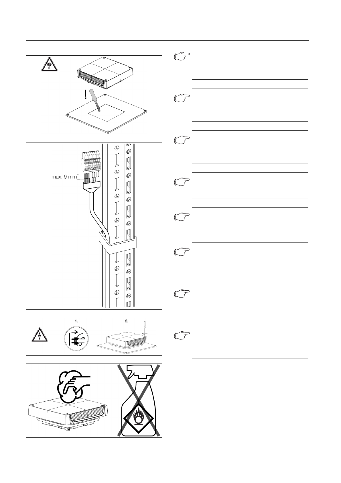
– The roof-mounted fan must only be connected to the
mains with the system de-energised. Connect the pre-
fuse specified in the Technical Specifications.
– Never insert your fingers into the rotating fan blade.
– The roof-mounted fan must only be fitted on a sealed
enclosure with protected access to the electrical con-
nection.
– Electrical connection and any repairs may only be car-
ried out by authorised, specialist personnel.
– Children and persons with limited cognitive/coordina-
tive abilities must not operate, maintain or clean the
unit or be allowed to use it as a toy.
– Spending long periods in the airflow may irritate the
eyes and muscles.
– If extinguisher gas is used in the enclosure, the roof-
mounted fan must be incorporated into the fire protec-
tion concept.
Danger!
A dangerous situation which will result in
death or severe injury if the instructions
are not followed.
Warning!
A hazardous situation which may lead to
death or serious injury if the instructions
are not followed.
Caution!
A hazardous situation which may lead to
(minor) injuries if the instructions are not
followed.
Note:
Important notices and indication of situations
which may result in material damage.

Rittal roof-mounted fan 5
3 Product description
EN
3 Product description
3.1 Components
Fig. 1: Product description
Legend
1Cover
2 Fan plate with fan
3 Inflow nozzle for air routing
4 Base tray with filter mats
5 Electrical connector
3.2 Function
The roof-mounted fan in conjunction with the corre-
sponding inlet filter(s) is used to dissipate heat loss from
enclosures and ventilate the enclosure, thereby protect-
ing temperature-sensitive components. This is achieved
via the direct infeed of ambient air, the temperature of
which must be lower than the admissible enclosure inte-
rior temperature.
3.2.1 Control
Rittal roof-mounted fans may be controlled more effi-
ciently with the following accessories:
* Not compatible with 3140.140.
3.2.2 Safety devices
The fan is equipped with a thermal winding protection for
protection against overload.
3.2.3 Filter mats
The roof-mounted fan is supplied with four class G3 filter
mats installed. The filter must be checked regularly de-
pending on the level of dust exposure, and replaced as
necessary.
3.3 Proper use
Rittal roof-mounted fans were developed and designed
in accordance with the state of the art and the recog-
nised rules governing technical safety. Nevertheless, if
used improperly, they may pose a threat to life and limb
or cause damage to property. The unit is only intended
for ventilating enclosures and electronic cases. Any oth-
er use is deemed improper. The manufacturer will not be
liable for any damages caused as a result of improper
use, or for incorrect assembly, installation or use. All risk
is borne solely by the user.
Proper usage also includes the observation of all valid
documents and compliance with the inspection and ser-
vicing conditions.
Accessories 3139.1x0 3140.1x0 3140.5x0
AC EC
Enclosure internal
thermostat
3110.000
■■■
Hygrostat
3118.000
■■■
Digital enclosure
internal tempera-
ture display and
thermostat
3114.200
■■■
Speed control
3120.200
■■* –
Sensor for speed
control 3235.450
––■
Control unit for
speed control
3235.440
––■
Tab. 1: Accessories

4 Installation
EN
6Rittal roof-mounted fan
3.4 Scope of supply
The roof-mounted fan is supplied in a packaging unit in
a fully assembled state and ready to connect.
Please check the scope of supply for completeness.
4 Installation
4.1 Choosing the installation site
When choosing the installation site for the enclosure,
please observe the following:
– The site for the enclosure, and hence the position of
the roof-mounted fan, must be carefully selected so as
to ensure good ventilation.
– The site must be free from excessive dirt and moisture.
– Roof-mounted fans must always be installed on hori-
zontal panels (roof).
– The ambient temperature must be lower than the ad-
missible enclosure interior temperature.
– The mains connection data as stated on the rating
plate of the unit must be guaranteed.
4.2 Notes on installation
4.2.1 General
Check the packaging carefully for signs of damage.
Any packaging damage may be the cause of a subse-
quent functional failure.
– The enclosure must be sealed on all sides (IP 54). If the
enclosure has a leak, unfiltered, contaminated air may
enter the enclosure.
– The fan motor is a rotating component that may trans-
fer vibrations and oscillations.
– Appropriate measures to decouple vibration must be
taken in advance by the company responsible for the
overall plant or system.
– During transportation, the roof-mounted fan must be
secured in accordance with section 4.3 "Installing the
roof-mounted fan" (installation for protection category
IP 55) to prevent damage.
4.2.2 Layout of the electronic components in the
enclosure
Take note of the air flows from the internal fans of in-
stalled electronic components.
When installing the roof-mounted fan, it is important to
ensure that the airflows of fans and built-in electronic
components do not adversely influence one another
(air short-circuit).
The corresponding minimum distances between the
fan and component must be observed in order to en-
sure unhindered air circulation.
Qty. Description
1Roof-mountedfan
1 Assembly and operating instructions
4 Standard filter mats (pre-installed)
1 EC declaration of conformity
1 Connector
Tab. 2: Scope of supply
Note:
The inlet filter must ensure an adequate air
exchange.

Rittal roof-mounted fan 7
4 Installation
EN
4.3 Installing the roof-mounted fan

5 Performing the electrical installation
EN
8Rittal roof-mounted fan
Step 1
Step 2
Step 4
Step 5
Step 6
5 Performing the electrical installa-
tion
5.1 Electrical connection
5.1.1 Notes on electrical installation
When performing the electrical installation, it is important
to observe all valid national and regional regulations as
well as the provisions of the responsible electrical supply
company.
The electrical installation must only be carried out by a
qualified electrician who is responsible for compliance
with the existing standards and regulations.
5.1.2 Connection data
– The connected voltage and frequency must corre-
spond to the values stated on the rating plate.
– The electrical installation and any repairs may only be
carried out by authorised specialist personnel.
Use only original spare parts!
Install the pre-fuse cited in the Technical Specifica-
tions (circuit-breaker or slow fuse) to protect from
short-circuits.
– If several fans are operated on a single pre-fuse, ob-
serve the total connected load.
– The roof-mounted fan must be connected to the
mains via an all-pole disconnecting device to overvolt-
age category III (IEC 61058-1).
5.1.3 Overvoltage protection and supply line load
– The unit does not have its own overvoltage protection.
Measures must be taken at the supply end by the
switchgear manufacturer or operator to ensure effec-
tive protection against lightning and overvoltage. The
limits specified in standard UL/IEC/EN 60335-2-40
must be observed.
– The units are classified as overvoltage category III. The
mains voltage must not exceed a tolerance of ±10%.
5.1.4 PE conductor connection
The PE conductor must be connected to the PE con-
ductor system of the overall system.
5.1.5 Installing the power supply
Remove the mains connector from the packaging and
connect to the mains as shown in the connection dia-
gram.
Note:
The position of the roof-mounted fan in the
mounting cut-out is freely selectable. It
should be based on the position of the elec-
trical connection inside the enclosure.
Note:
No filter mats are needed in order to achieve
protection category IP 20.
Note:
Check that the clips are completely snapped
into place to ensure that the roof-mounted
fan is securely held in the mounting cut-out.
Note:
The filter mats may be removed to achieve a
higher air throughput. In this case, the pro-
tection category will be reduced to IP 22 and
UL Type 1.
Note:
Use only original Rittal filters which bear the
Rittal logo to be sure of the protection cate-
gory, air throughout and approvals.
Note:
You should inspect the filter regularly de-
pending on the amount of dust. Recom-
mended: Replace after 2,000 operating
hours at the latest, and as and when neces-
sary.
Note:
The side with the Rittal logo must be pointing
towards the fan.
Note:
The orientation of the cover on the base tray
is freely selectable.

Rittal roof-mounted fan 9
5 Performing the electrical installation
EN
Fig. 2: Connection diagrams
Select the conductor cross-section according to the
pre-fuse (0.5–4 mm² single-wire, 0.5–2.5 mm² fine-
wire).
A smaller pilot wire may be selected (min. 0.34 mm²).
Fig. 3: Connector and strain relief
Key
1 Strain relief
Connect the connector to the roof-mounted fan from
below.
5.2 Installing the pilot wire
To control the EC roof-mounted fans via an external
control unit (e.g. 3235.440), types 3140.5xx have addi-
tional connections for the pilot wire.
Release and remove the jumper between the "+10 V"
and "0 – 10 V/PWM" (terminals 1 and 2) connections.
Use a screwdriver with a 3.5 x 0.5 mm blade.
Open the terminal with the screwdriver and insert the
connection cable as shown in the connection dia-
gram.
Remove the screwdriver.
Connection Pin Function/assignment
L Power supply
N Neutral conductor
PE PE conductor
+10 V 1 Voltage output 10 V max. 1.1 A,
galvanically isolated, not short
circuit-protected
0…10 V/PWM 2 Control input 0…10 V or PWM,
galvanically isolated, impedance
100 kΩ
GND 3 GND connection of the control
interface
Speed 4 Speed output Open Collector, 1
pulse per revolution, galvanically
isolated
Tab. 3: Connection designations
Note:
In accordance with NFPA 70 (NEC), only
copper conductors must be used to connect
the supply cable to the mains connector.
Note:
To operate without a pilot wire, the jumper
should be left in the connection terminal. The
unit will then be operated at maximum
speed.

6 Commissioning
EN
10 Rittal roof-mounted fan
Fig. 4: Pilot wire
Key
1 Max. speed (as delivered, with jumper between the
"+10 V" and "0 – 10 V/PWM" connections.
2 Adjustable speed
3 Adjustable speed via PWM 1 – 10 kHz
4 Adjustable speed via potentiometer
6 Commissioning
Once all the assembly and installation work is com-
plete, switch on the power supply to the roof-mounted
fan.
The roof-mounted fan operates automatically, in other
words, the fan will start up once the power has been
switched on.
7 Inspection and maintenance
The installed maintenance-free fan is mounted on ball
bearings, protected against moisture and dust, and fit-
ted with a temperature monitor.
The life expectancy is at least 50,000 operating hours
(L10, 40°C).
The roof-mounted fan is therefore largely maintenance-
free.
From time to time, the components may need to be
cleaned using a vacuum cleaner or compressed air if
they become visibly dirty.
Any stubborn, oily stains may be removed using a non-
flammable detergent, such as degreaser.
Sequence of maintenance work
– Check the level of dirt: If necessary, vacuum the fan
housing, or clean with compressed air.
– Filter soiling: Replace the filter.
– Check the noise generation of the fan.
8 Storage and disposal
Facilities for disposal are available at the Rittal plant.
Please contact us for advice.
Note:
EC roof-mounted fans start running with a
delay of approx. 15 sec.
Note:
The roof-mounted fan must not be exposed
to temperatures above +70°C or below
-30°C whilst in storage.

Rittal roof-mounted fan 11
9 Technical specifications
EN
9 Technical specifications
Unit 3138.000 3139.100 3139.110 3140.100 3140.110 3140.140 3140.500 3140.510
Electrical specifications
Rated operating voltage V
Hz
Without fan
motor
Pre-fuse A – 3 3 3 3 – 3 3
Motor circuit-breaker – – – – – 0,2...0,4 – –
Rated insulation voltage
(U
i
)
V – 300
Rated impulse with-
stand voltage (U
imp
)
kV – 4 2
Controlinterface ––––––■■
Dimensions
Width (B1) x depth (T1) mm 400 x 400
Required mounting cut-
out (B2 x T2)
mm 258 x 258 ±2
Height (H1) mm 133
Maximum installation
height (H2)
mm 27.5 34.6
Air throughput (for performance diagrams, see Rittal homepage)
Air throughput, unim-
peded air flow (without
filter mats)
m³/h – 500/525 500/525 873/965 873/965 863/942 1069 1069
Air throughput, unim-
peded air flow (with filter
mats)
m³/h – 417/446 446 725/759 759 700/749 841 841
Air throughput (with fil-
ter mats and inlet filter)
1 x 3243.200 m³/h – 370/391 391 590/610 610 580/610 690 690
Fan – Radial / capacitor motor Radial / ro-
tary current
motor
Radial / EC motor
Electromagnetic compatibility
Immunity to interference – For industrial areas to EN 61000-6-2
Emitted interference – For residential, business and commercial areas and small companies to EN 61000-6-3
Other
Noise level (with filter
mats)
Noise level (without filter
mats)
Tab. 4: Technical specifications for roof-mounted fans
220…240,
1~, 50/60
115, 1~, 60 220…240,
1~, 50/60
115, 1~, 60 380…415,
3~,50/60
400…480,
3~, 60
220…240,
1~, 50/60
115, 1~, 60
Rated current max.
A – 0,23/0,27 0,56 0,43/0,56 1,2 0,17/0,2 1 1,51
Power consumption
W – 51/62 65 99/130 138 90/122 129 112
98/130
2 x 3243.200 m³/h – 400/428 428 680/700 700 650/695 785 785
dB (A) – 52/54 54 58/60 60 56/58 60 60
dB (A) – 54/56 56 60/62 62 60/61 63 63

9 Technical specifications
EN
12 Rittal roof-mounted fan
Fig. 5: Dimensions
Operating temperature
range
°C -20...+55
Storage temperature
range
°C -40...+70
Protection category (to
IEC 60 529)
IP 21 (without filter mat and installation in accordance with section 4.3 “Installing the roof-mounted fan” –
Installation for protection category IP 21)
IP 21 (without filter mat and installation in accordance with section 4.3 "Installing the roof-mounted fan" –
Installation for protection category IP 55)
IP 55 (without filter mat and installation in accordance with section 4.3 "Installing the roof-mounted fan" –
Installation for protection category IP 55)
Accessories Packs of
Spare filter mats (filter
class G3)
12 pc(s). 3174.100
Enclosure internal ther-
mostat
1 pc(s). – 3110.000
Digital enclosure inter-
nal temperature display
and thermostat
1 pc(s). – 3114.200
Hygrostat 1 pc(s). – 3118.000
Speed control 1 pc(s). – 3120.200 –
Sensor for speed con-
trol
1 pc(s). – – – – – – 3235.450
Control unit for speed
control
1 pc(s). – – – – – – 3235.440
Outlet filter 1 pc(s). 3243.200
Unit 3138.000 3139.100 3139.110 3140.100 3140.110 3140.140 3140.500 3140.510
Tab. 4: Technical specifications for roof-mounted fans


◾Enclosures
◾ Power Distribution
◾ClimateControl
◾ IT Infrastructure
◾ Software & Services
You can find the contact details of all
Rittal companies throughout the world here.
www.rittal.com/contact
3nd edition 05.2019/ ID no. 335 522 / Drawing no. D-0000-00000432
This manual suits for next models
7
Table of contents
Popular Fan manuals by other brands

Vents
Vents Quiet-dMEV 100 DC user manual

Harbor Breeze
Harbor Breeze LANDON LAN52SS5L manual

SUNTEC
SUNTEC KLIMATRONIC CoolBreeze 3500 BV user manual

COOK
COOK PLC Installation, operation and maintenance manual

ELTA FANS
ELTA FANS MORI dMEV II T installation manual

ACUTRONIC
ACUTRONIC MONSOON Instructions for use