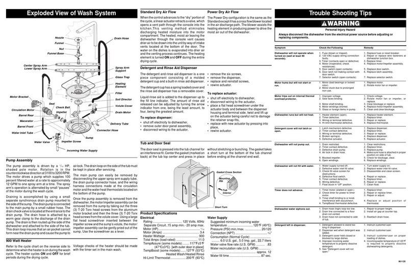
TroubleShootingTipsExplodedViewofWashSystem
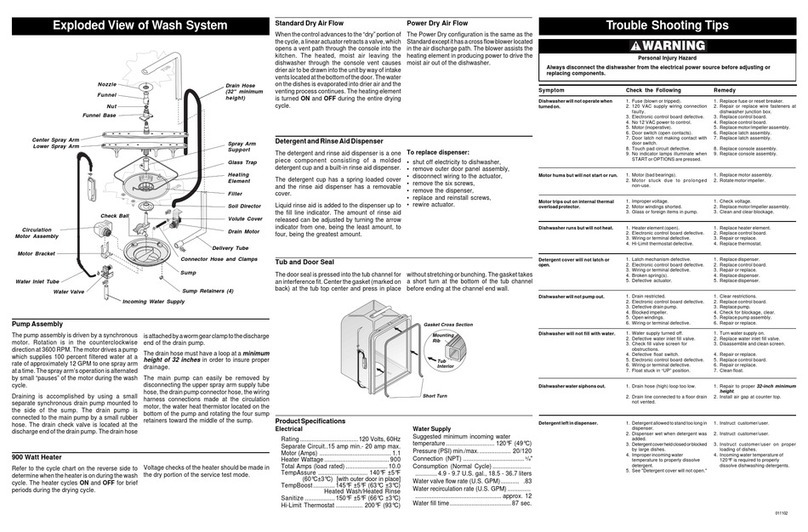
Tub and Door Seal
Thedoorsealispressedintothetubchannelfor
aninterferencefit.Centerthegasket(markedon
back)at thetubtop centerandpress inplace
ProductSpecifications
Electrical
Rating .......................... 120Volts,60Hz
SeparateCircuit..15ampmin.-20ampmax.
Motor(HP) ..................................... 1
/12
Motor(Amps) ................................. 3.4
HeaterWattage .............................. 900
TotalAmps(loadrated) ................... 11.0
TempAssure ....................... 140°F±5°F
(60°C±3°C) [withouterdoorinplace]
TempBoost ......... 145°F±5°F (63°C±3°C)
HeatedWash/HeatedRinse
Sanitize ............. 150°F±5°F (66°C±3°C)
Hi-LimitThermostat ............ 200°F(93°C)
WaterSupply
Suggestedminimumincomingwater
temperature ...................... 120°F(49°C)
Pressure(PSI)min./max. ............... 20/120
Connection(NPT) ............................ 3/8"
Consumption(NormalCycle) .................
..........4.9- 9.7 U.S.gal.,18.5-36.7 liters
Watervalveflowrate(U.S.GPM) ........ .83
Waterrecirculationrate(U.S.GPM) ..........
........................................ approx.12
Waterfilltime ............................ 87sec.
removethesixscrews,
removethedispenser,
replaceandreinstallscrews,
rewireactuator.
To replace actuator:
shutoffelectricitytodishwasher,
disconnectwiringtotheactuator,
placeaflatheadscrewdriverundertheactuator
bodyandbetweenthedispenserhousingand
terminalside,twistandliftupontheactuator
beingcarefulnottodamagetheretainer
snap-fits,
replacewithnew actuatorbypressinginto
place,
rewireactuator.
PowerDry Air Flow
ThePowerDryconfigurationisthesameasthe
Standardexceptithasacrossflowblowerlocated
intheairdischargepath.Theblowerassiststhe
heatingelementinproducingpowertodrivethe
moistairoutofthedishwasher.
ChecktheFollowing
1. Fuse (blownortripped).
2. 120 VACsupplywiringconnection
faulty.
3. Electronic controlboarddefective.
4. No 12VACpowertocontrol.
5. Motor(inoperative,check
resistances).
6. Door switch(opencontacts).
7. Doorlatchnotmakingcontactwith
doorswitch.
8. Touch padcircuitdefective.
9. No indicatorlampsilluminatewhen
STARTorOPTIONSarepressed.
1. Motor(badbearingsorlockedrotor).
2. Motor stuck due to prolonged
non-use.
1. Improper voltage.
2. Seal facesbinding.
3. Motor shaftbinding.
4. Motorwindingsshorted.
5. Glass orforeignitemsinpump.
1. Heater element(open).
2. Electronic controlboarddefective.
3. Wiring orterminaldefective.
4. Hi-Limitthermostatdefective.
1. Latch mechanismdefective.
2. Electronic controlboarddefective.
3. Wiring orterminaldefective.
4. Broken spring(s).
5. Defective actuator.
1. Drain restricted.
2. Electronic controlboarddefective.
3. Defectivedrainpump.
4. Airlockindrainhose.
5. Blocked impeller.
6. Openwindings.
7. Wiring orterminaldefective.
1. Water supplyturnedoff.
2. Defective waterinletfillvalve.
3. Checkfillvalvescreenfor
obstructions.
4. Defective floatswitch.
5. Electronic controlboarddefective.
6. Wiring orterminaldefective.
7. FloatstuckinUPposition.
1. Drain hose(high)looptoolow.
2. Drain lineconnectedtoafloordrain
notvented.
3. Drainhosenotconnectedtosideof
tub.
1. Detergent allowedtostandtoolong
indispenser.
2. Dispenser wetwhendetergentwas
added.
3. Detergent cover held closed or
blockedbylargedishes.
4. Improper incomingwater
temperaturetoproperlydissolve
detergent.
5. See "Detergentcoverwillnotopen."
Always disconnect the dishwasher from the electrical power source before adjusting or
replacingcomponents.
PersonalInjuryHazard
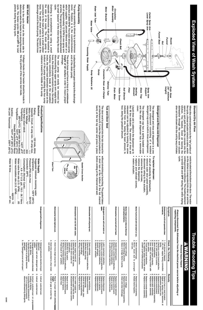
Nozzle
Funnel
Nut
FunnelBase
CenterSprayArm
LowerSprayArm
900WattHeater
Referto thecyclechart onthe reverse sideto
determinewhentheheaterisonduringthewash
cycle.The heatercyclesON and OFF forbrief
periodsduringthedryingcycle.
Voltagechecksoftheheatershouldbemadein
thedryportionoftheservicetestmode.
airlock.Thedrainlooponthesideofthetubmust
bekeptinplace afterservicing.
The main pump can easily be removed by
disconnectingtheuppersprayarmsupplytube,
thedrainpumpconnectorhose,andthewiring
harnessconnections made atthecirculation
motorandthewaterheatthermistorlocatedon
thebottomofthepump.
Oncethepumpassemblyisremovedfromthe
dishwasher,themotor/impellerassemblycanbe
removedfromthesumpbytakingoutthethree
(3)T-20Torxheadscrewsfromthe aluminum
motorbracketandthenthe three (3) T-20Torx
headscrewsfromthevolutecover.Usingalarge
flathead screwdriverinserted betweenthe
impellerscrewandthesumpsvolute,themotor/
impellerassemblycanbegentlypriedoutofthe
sump.Usethescrewdriverasalever.
PumpAssembly
The pump assembly is driven by a 1/12 HP,
shaded pole motor. Rotation is in the
counterclockwisedirectionat3100to3200RPM.
Themotordrives a pumpwhichsupplies100
percentfilteredwateratarateofapproximately
12GPMto one sprayarmatatime. The spray
armsoperationisalternatedbysmallpauses
ofthemotorduringthewashcycle.
Draining is accomplished by using a small
separatesynchronousdrainpumpmountedto
thesideofthesump.Thedrainpumpisconnected
tothemainpump byasmallrubberhose.The
draincheckvalveislocatedattheentrancetothe
drainpump. Thedrain hoseisattached bya
wormgearclamptothe discharge of thedrain
pump.Thedrainisthenroutedupthesideofthe
dishwasherandattachedtothesideofthetub.
Thisdrainloopinsuresthatanairpocketcannot
formnearthedrainpumpandcausethepumpto
withoutstretchingorbunching.Thegaskettakes
ashort turnat the bottomof thetubchannel
beforeendingatthechannelendwall.
Short Turn
IncomingWaterSupply
DrainHose
SprayArm
Support
GlassTrap
Heating
Element
Filter
Soil Director
VoluteCover
DrainMotor
DeliveryTube
ConnectorHose
MotorBracket
CirculationMotor
WaterInletTube
WaterValve
Check Ball
Impeller
Sump
ImpellerScrew
Gasket Cross Section
Detergent and Rinse Aid Dispenser
Thedetergentandrinse aiddispenserisaone
piece component consisting of a molded
detergentcupandabuilt-inrinseaiddispenser.
Thedetergentcuphasaspringloadedcoverand
therinseaiddispenser has a removablecover.
Liquidrinseaid is addedtothedispenserup to
thefill lineindicator. Theamountof rinseaid
releasedcanbeadjusted by turningthearrow
indicatorfromone, being theleastamount,to
four,beingthegreatestamount.
To replace dispenser:
shutoffelectricitytodishwasher,
removeouterdoorpanelassembly,
disconnectwiringtotheactuator,
Mounting
Rib
Tub
Interior
Remedy
1. Replacefuseorresetbreaker.
2. Repair or replace wire fasteners at
dishwasherjunctionbox.
3. Replacecontrolboard.
4. Replace transformer.
5. Replace motor/impellerassembly.
6. Replacedoorswitch.
7. Replace latchassembly.
8. Replaceconsoleassembly.
9. Replaceconsoleassembly.
1. Replace motor.
2. Rotate motorfanorimpeller.
1. Check voltage.
2. Rotate motor fan or impeller, or
replace.
3. Clear blockage orreplace.
4. Replace motor/impellerassembly.
5. Cleanandclearblockage.
1. Replaceheaterelement.
2. Replacecontrolboard.
3. Repairorreplace.
4. Replace thermostat.
1. Replace dispenser.
2. Replacecontrolboard.
3. Repairorreplace.
4. Replace dispenser.
5. Replace actuator.
1. Clear restrictions.
2. Replacecontrolboard.
3. Replace pump.
4. Make surehoseisattached in proper
positiononsideoftub.
5. Check forblockage,clear.
6. Replace windings.
7. Repairorreplace.
1. Turn watersupplyon.
2. Replace waterinletfillvalve.
3. Disassemble andcleanscreen.
4. Repairorreplace.
5. Replacecontrolboard.
6. Repairorreplace.
7. Clean float.
1. Repairtoproperheight.
2. Install airgapatcountertop.
3. Reattach drainhose.
1. Instruct customer/user.
2. Instruct customer/user.
3. Instruct customer/user on proper
loadingofdishes.
4. Incoming watertemperatureof
120°Fisrequiredtoproperly
dissolvedishwashingdetergents.
Symptom
Dishwasher will not operate when
turned on.
Motor hums but will not start or
run.
Motor trips out on internal thermal
overload protector.
Dishwasher runs but will not heat.
Detergent cover will not latch or
open.
Dishwasher will not pump out.
Dishwasher will not fill with water.
Dishwasher water siphons out.
Detergent left in dispenser.
Seal
Barrel Front
Macerator
Barrel Rear
StandardDry Air Flow
Whenthecontroladvancestothedryportionof
thecycle,alinearactuatorretractsavalve,which
opensaventpaththroughtheconsoleintothe
kitchen.This venting method eliminates
dischargingheated moistureinto the motor
compartment.Theheated,moistairleavingthe
dishwasherthroughtheconsole ventcauses
drierairtobedrawnintotheunitbywayofintake
ventslocated atthe bottomofthe door.The
wateronthedishes isevaporatedintodrierair
andtheventingprocesscontinues.Theheating
elementisturnedON andOFF duringtheentire
dryingcycle.
0002(ELEC)
