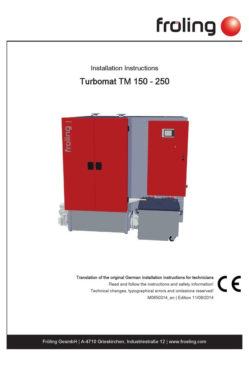
Froling TURBOMAT TM 150 User manual

Operating Instructions
TURBOMAT
TM 150 / 220
B0310003 Fröling Heizkessel und Behälterbau Ges.m.b.H., Industriestraße 12, A-4710 Grieskirchen
DRV.: 164852 . Manuf. Manual No.:99229a. UID-Nr.: ATU 22256902 Firmenbuch-Gericht: Kreis- und Handelsgericht Wels . ARA-License no.: 4480

2 B0310003 Edition 2003
General
Dear Customer,
You have chosen to purchase one of our firm's quality products. We appreciate your choosing our
product and we hope that you too will soon join the growing number of satisfied customers.
Our systems represent the culmination of many long years of experience and the on-going
development of the latest technological advances which result from that experience.
Conscientious processing and control are the most important objectives in our firm. Defects can
rarely be 100% ruled out, so, if in spite of all our efforts a defect should appear, our generous
guarantee provides you with a high degree of security.
It's important to note, however, that even the best-designed product will only perform well over a
long period of time if it is properly serviced and operated.
Grieskirchen, August 2003
FRÖLING on the Internet
On our Internet site, you can find information on our complete list of products or request more
detailed information 24 hours a day.
What's more, you will find current information on new developments and trends at Fröling and in
the boiler field.
Internet Address: http://www.froeling.com

Edition 2003 B0310003 3
Table of Contents
Page
Permitted Fuels 4
Technical Data 5,6
Safety Information 7
Start-up 8
Emergency Operation using Firewood 8
Steps to Take during Malfunctions 9
Servicing, Cleaning 10-14
Instructions for Measuring Emissions 15
Conformity Certificate 16
Operating the Controller 17-26
Quick Reference Guide 18
Adjusting the Boiler 23
Adjusting the Heating 21
Setting the Clock Time 23
Fault Messages, Eliminating Faults 25-26

4 B0310003 Edition 2003
Use of Fuels
The wood-chip system of the TURBOMAT series is intended exclusively for heating domestic water.
Only the fuels described below may be used:
Waste-wood
Waste wood water content:
Designation Type
W20 air-dried
W30 storage stability
W35 limited storage only
Waste-wood size:
For Austria, the following applies: Waste-wood ÖNORM M 7133
Energy waste-wood G 30 (finely chopped waste-wood)
Energy waste-wood G 50 (medium-sized waste-wood)
For Germany, the following applies:
Waste-wood with a maximum edge length of 50 mm as per fuel class 4
Federal Emissions Protection Ordinance (BimSchV) dated 15 July 1988)
Pellets:
For Austria, the following applies: Pellets as per PVA - quality symbol
For Germany, the following applies: Pellets as per DIN 51731
Shavings:
Saw dust and carpentry waste can only be used in systems equipped with rotary valves!
For Austria, the following applies: ECO STANDARD M 7133
For Germany, the following applies: 1. BlmSchV, Fuel class 4
Due to various air-quality protection regulations, the following fuels must not be used:
- Cardboard waste, treated wood-wastes, pure grinding dust,
- rubbish, large quantities of paper, cartons and
- Coal (brown coal, anthracite coal, briquettes)
Using other than permitted wood-wastes will void your warranty.
In addition, the combustion chamber is susceptible to damage caused by burning plastics and finishes.
The caustic layers will damage the boiler or the Lambda probe.
What's more, the condensation which forms from burning damp fuel (water content>35%!) can cause seepage
or corrosion in the combustion chamber, heat-exchanger, and chimney.

Edition 2003 B0310003 5
Technical Specifications
Technical documentation lt. Agreement between the Austrian Federal Regions as per Art. 15b B-
VG on protective measures with regard to small boiler systems or energy conservation
Boiler Type: Waste-wood Boiler, Turbomat
Manufacturer: FRÖLING Heizkessel- und Behälterbau Ges.mb.H.
Industriestrasse 12, 4710 Grieskirchen
Data 150 220
Measured Quantity Unit Boiler Size
Rated heating efficiency kW 150 200
Heating efficiency range kW 50-150
Fuel-heating efficiency at rated
heating efficiency kW 164.8
Permitted fuel See page 4
Fuel through-put at rated
heating efficiency kg/h 50 67
Flue gas temperature °C 190 190
Flue gas mass flow at G 50 m³/h 664 885
Necessary draught requirement Pa 20 20
Flue gas pipe diameter mm 200 250
Permitted operating pressure bar 3 3
Permitted operating temperature °C 95 95
Testing Institute TÜV
Test report no.
Exhibition Date 01.08.2003
Carbon monoxide (CO) mg/MJ 39
Nitrous oxide (NOx) mg/MJ 91
Organ. Hydrocarbons (OGC) mg/MJ 2
Dust mg/MJ 18
Boiler Efficiency Rating % 91.0
Store Required Recommended

6 B0310003 Edition 2003
Technical Specifications
Waste-wood Boiler Turbomat 150 / 220
Rated heat output kW 150 200
Permissible working over-pressure bar 3 3
Permissible outfeed temperature °C 95 95
Minimum return feed temperature °C 55 55
Boiler contents (water ) Liters 385
Total boiler mass kg 1690
Chamber/Heat-exchanger kg 940 / 750
Upstream resistance (T=20K)
Flow-through (∆T = 20K) m³/h 6.44 9.45
Chimney Construction Data:
Flue gas temperature °C 190 190
Amount of fuel required at G50 W30 kg/h 50 67
Flue gas mass flow at G50 W 20 Lambda=2 m³/h 664 885
Necessary draught requirement at the chimney Pa 15/8 20/10
Flue gas pipe diameter mm 200 250
Structural Dimensions
L Boiler depth mm 3230 3390
B Boiler width mm 1210 1490
H Boiler height
1)
mm 1870 1870
H1/H2 Outfeed/return feed height mm 1930 / 495 1930 / 495
H3Flue pipe height
860
H4 Height of stoker connection (with blow-back flap) mm 775 860
H5 Height of induced draught unit mm 1970 1970
H6 Height of flue gas return mm 2365 2365
Outfeed/return feed connection DN 65 65
Connection for thermal discharge safety device sleeve 1/2" 1/2"
L1 Length of boiler mm 1710 1750
L2 Length of induced draught fan mm 600 670
L3 Depth from back wall to centre of stoker mm 1200 1240
L4 Length of ash trolley for chamber ash removal mm 930 930
B1 Width of ash trolley for chamber ash removal mm 550 550
B2 Width of heat-exchanger
mm 870 570
B3 Distance from centre of stoker to the boiler mm 630 630
B4 Length of stoker (incl. gearing) mm 845 845
Min. clearance height 1,950 mm Dimensions in mm, technical modifications are not authorized
Min. clearance width 1,000 mm
H
3
5
6
7
11
B
2
H
2
H
1
8
9
1
0
12
B
H
12
3
4
L
4
L
1
L
2
B
4
H
5
L
1 ..Conveyor grate 5 ..Upper cleanout port door 9 ..Outfeed
2 ..Ash rake 6 ..Upright heat-exchanger 10 ..Return feed
3 ..Stoker screw 7 ..Induced draught fan 11 ..Ash trolley
4 ..Combustion chamber door 8 ..Combustion air blower fan 12 ..Ashcan

Edition 2003 B0310003 7
Assembly
1.....Outfeed
2.....Return feed
3.....Induced draught fan
4.....Combustion air blower fan
5.....Ash trolley
6.....Ash screw drive
7.....Ash can
8.....Ash can screw drive
9.....Conveyor grate
10...Ash rake
11...Grate and rake drive
12...Stoker screw drive
13...Stoker screw
14...Blow-back flap
15...Feed screw drive
16...Lambda probe (3/4” connector)
17...Flue gas sensor (1/2” connector)
18...Heat exchanger drive
19...STB housing
20...Undepressure measuring port
21....Underpressure measuring connector
22....Boiler sensor, STB sensor
23....Safety battery sensor
24....Safety battery connections
25....Combustion chamber temperature sensor
26....RGTW (combustion chamber overpressure)
27....Primary air setting motor
28....Secondary air setting motor
29 ...Igniter
30....Cleaning port

8 B0310003 Edition 2003
Safety Information
As a rule, the operator is not authorized to modify the safety equipment, to
make substitutions, to by-pass any systems, or to change the settings.
The boiler system's type and power rating also may not be modified without the
concurrence of an expert.
In order to avoid burn injuries, the boiler is only to be operated using the
handles provided. For the same reason, you should avoid touching the flue
pipes during operation.
The operating door is located behind the insulating door. It can only be opened
if the induced draught fan is running or starts running after the insulating door is
opened.
Caution: - Open the fill tank doors slowly when system is operating
(explosions)
If this is not the case, the temperature monitor safety device has disengaged
the induced draught ventilator (See function below: "Five systems to prevent
over-heating"). Opening the doors when the induced draught is not running
could allow the incompletely burned gases in the boiler to escape into the boiler
room, resulting in a powerful explosion!
Five devices to counter over-heating:
•Boiler controller: switches off the boiler if the boiler temperature is set 5°C
above the set value
•Temperature monitoring safety device (via control system): disengages the
boiler if it reaches a temperature of 93°C, so that it can automatically re-
engage once the temperature drops below 89°C.
•Thermal discharge safety device: opens a valve when the temperature
reaches 95°C or 100°C. This valve allows cold water to flow into the boiler's
safety heat-exchanger, to draw off the heat from the boiler and prevent its
temperature going any higher. Using the water from the thermal discharge
safety device or from the heating system as domestic hot water is absolutely
forbidden.
•Safety temperature limiter: disengages the induced draught when the boiler
temperature reaches 100°C (the pumps continue to run). Physically unlatch
the safety temperature limiter situated on the back side, as soon as the
temperature has again dropped below 95°C (screw off the cap and push in the
head approximately 0.5 cm using a matchstick or a small screw-driver).
•Safety valve (SV): If all the previously mentioned systems fail to prevent a
continuing rise in temperature, the system pressure will also rise (up to 2.5 or
3 bar). If this is the case, the safety valve opens and vents off the hot water in
the form of steam. If this should happen, water must be added before a new
system start-up.

Edition 2003 B0310003 9
Start-up
Initial Start-up
The initial start-up must be carried out by an authorized installer or Fröling's customer service department!
Checking the Heating System:
1. Check all electrical equipment
2. Check to see whether the heating system has been completely vented.
3. Check to see whether all the safety devices are in place and ensuring they are functioning properly.
4. Check to see whether there is sufficient ventilation and venting of the boiler room.
5. Configure and set parameters
6. Prepare the Fuel
Fill the fuel storage room with waste-wood or pellets, depending on the type of system.
IMPORTANT! The conveyor in the storage room must be switched on during the filling process
7. Pre-heating: See description page 17
Pre-heat the system at low power until the combustion chamber has dried out.
Turn the temperature controller to 70°C!

10 B0310003 Edition 2003
What to do if unit stops operating
If you discover damage to the heat producing component (boiler), the expansion tank, or the safety equipment,
you must discontinue operating the system.
Check the power supply (fuses) or the switchgear panel fuses
Boiler controller correctly set (everything on "AUTO")
Check the safety temperature limiter (See page 7)
The boiler temperature can't be throttled:
Too much material (See page 22)
Chimney draught too high (> 0.3 mbar) - Install draught controller!
Door seal not sound (boiler is burning with too much dead air)
Boiler output is too low:
Boiler is probably dirty - See pages 10 - 13 "Maintenance and Cleaning"
(See page 4 "fuels") - Solution: use a better quality of fuel
Over-heating:
If the boiler system should over-heat in spite of all the safety systems, take the following
precautions:
- Keep all doors and covers closed on the boiler
- Switch on all the pumps and open the stirrer
- Leave the boiler room
- Inform customer service
If fault messages appear on the boiler controller display, see the error message list!
For faults that occur on a frequent basis (safety temperature limiter has fallen) or for faults that can't be
cleared by the operator, notify the installer, heating technician, or our customer service.

Edition 2003 B0310003 11
Maintenance
In order to achieve optimum combustion, problem-free automatic operation, and good system
efficiency, ash and unburned residual fuel must be removed from the combustion chamber and the
settling chamber under the heat-exchanger at regular intervals.
This is also necessary for systems with automatic heat-exchanger ash removal.
On the Turbomatic 85 - 110, the ash from the settling chamber under the heat-exchanger is
likewise fed into an ash box by an ash screw.
Boiler condensation:
A return feed lift must ensure that the return feed temperature never falls below 55°C. Otherwise
premature corrosion of the heating surfaces is possible.
Therefore, during shut-down periods in the summer months, you must ensure that all of the boiler
circuit water is circulated at least 1 x per week, to prevent sediments and changes to the
concentrations.
If the system in not operated during the winter, it should be completely emptied by a trained
technician (danger of freezing, which could destroy the boiler or the pipes). Otherwise, the system
remains filled.
Filling or re-filling the system is done with the stirrer half-opened, pump disengaged, and check
valves open. No special requirements are made on the quality of the water used, but avoid over-
supplying the system (See page 5 "Standards, Regulations, and Equipment")
The boiler must only be cleaned when the system is disconnected.

12 B0310003 Edition 2003
Maintenance and cleaning:
Weekly tasks:
- Emptying the ash box:
Depends on the operating hours and the heating material (bark content) and should be done
when it reaches 2/3 full. The ash box can be removed in its entirety or it can be emptied
using a vacuum. In addition, the flue dust from the settling chamber (Pos 8) under the heat-
exchanger must be removed using a scraper or ash vacuum.
- For TM 150, there are two ash boxes with a capacity of either 180 l or 25 l,
so that the settling chamber under the heat-exchanger is automatically emptied.
- Check system pressure
The manometer should indicate 1 - 1.5 bar (in the cold state) depending on the system
configuration or approximately 0.2 bar above the supply pressure of the expansion tank (in
the heated state). If the system pressure is constantly less than this, water must be added. If
this happens frequently, please consult your installer, since there may be an unsound seal
somewhere in the heating system . Too much fresh water (from frequent refilling) can cause
calcification of the boiler. Result: Decrease in output or breakdown. If significant fluctuations
are noted at the manometer, the expansion tank is probably defective or too small (not
sized properly) (See page 13 "Checking the Expansion Tank").

Edition 2003 B0310003 13
Maintenance and cleaning:
Monthly tasks:
- Clean the boiler:
Open the combustion chamber door and switch on the ash screw and the conveyor grate.
Sweep or vacuum the remaining ash in the combustion chamber forwards onto the ash
screw .
(For switching on the ash screw and grate, see below)
Winter operation
Heating SET
MANUAL
OPERATION
TEST MODE
- Boiler temp.
- Flue gas temp.
- Slide-in
- Blower
- Primary air
- Residual O2
- Secondary air
- Boiler pump
- Boiler temp.
- Boiler pump
- Outside temp.
- Outfeed 1
- Outfeed 2
- Day: Th 09/07/02
- Time: 13:30:00
- Version: 13.12
- Running time
- Type: Turbomatic
- Board temp.
- The boiler
must be
- Operator name:
CUSTOMER
-
- Stoker screw forward/backward
- Raise blow-back flap
- Ash screw forward/backward
- Heat-exchanger drive
- Tipping drive (grate tipping)
Feed screw forward/backward
Enter
Back
Enter
Back
Annual tasks:
- Clean flue gas sensing elements (picture Pos1):
Release the threaded pin and remove the sensing element from the flue gas pipe, wipe off
the sensing element with a clean cloth and then re-install it.
- Check induced draught blower fan for dirt and clean it (Pos2):
After opening heat-exchanger cleaning port cover (Pos3), a visual check will determine
whether the blower fan's traveling wheel must be removed for cleaning.
If dirt or ash have collected, carefully clean (with a soft brush, paintbrush, etc.). While doing
this, take care that the attached clips don't slip. The clips are balancing weights, which
guarantee a smooth, even run. If the clips are altered in any way, the ventilator will not run
smoothly. It will become too loud and will need to be replaced, since the motor bearings will
soon be damaged.
- Check the heat-exchanger for dirt - perform visual check or clean (Pos3)
Open the heat-exchanger cleaning port cover (Pos3) and clean the settling chamber with the
brush provided
- Check supply-air blower fan for contaminants (dust, for example) (Pos9)
If there is dirt, remove the protective grating and clean the traveling wheel with a cloth or
compressed air.

14 B0310003 Edition 2003
Maintenance and cleaning:
- Remove the separating plates (Pos5) and remove the accumulated soot deposits with the ash
scraper.
Also clean the boiler's inner walls.
- Check the firebrick for damage (Pos6)
Open the combustion chamber door and perform a simple visual check of the combustion
chamber (small fissures or a rough surface are normal)
- Check the grate; to see whether the grate elements have shifted (Pos7)
Open the combustion chamber door and perform a simple visual check
- Blow out any obstructions in the over-pressure monitor (Pos11)
On the TM 150, also blow out the under-pressure measuring port with air (Pos12)
(CAUTION: Do not blow air into the differential pressure measuring transducer)
- Check the gearbox for a good seal (Pos10)
Important: As the system operator, you are legally obligated to have the thermal discharge safety
device operationally checked annually by a specialist.
- Thermal discharge safety device
Press the test button - water must flow into the discharge funnel. After releasing the button,
the funnel must seal again. If the amount of discharged water was very low, the thermal
discharge safety device or the safety battery is calcified and must be flushed out with a de-
liming agent (thinned formic acid, for example). If the amount continues to decrease, the
seals and the valve set must be cleaned.
- Safety valve
The safety valves have a test button. Press the test button. If the valve is operating correctly,
water comes out. After the test button is released, the valve must re-seal!
- Expansion Tank
There is a test valve on each expansion tank (similar to the valve on a vehicle tire), which
can be briefly actuated (pressed in). If water comes out, the expansion tank is defective. If
nitrogen (anti-corrosion protection) comes out, everything is okay. However, to see clear
evidence of the system's operability, the water pressure in the heating system must first be
lowered to 0 bar.
Have it checked by a specialist if necessary
- Soundness of door seals
By actuating the door, you can check to see whether it still closes tightly (by drawing shut).
Next, check the ceramic fibre seal, to see whether it is still properly aligned on the door
frame (by the imprint in the ceramic fibre cord). If not properly aligned, this will be evidenced
by a black discoloration or a break in the imprint. If the soundness of the seal is no longer
assured, the door latches must be re-tightened or the seal must be replaced.
- Check the chimney and the connection line to the chimney
The chimney should be regularly serviced (by a chimney sweep). After the chimney is
cleaned, it is imperative to also have the connection line from the boiler to the chimney
checked for sediments (for example due to chimney cleaning)
- Check explosion flap and/or draught controller flap
Check the explosion flap (and the draught controller too, if there is one) for ease of
operation.

Edition 2003 B0310003 15
Instructions for measuring emissions
Clean the system three days before the measurement (not on the same day, since this
unnecessarily stirs up the ash, which can lead to increased dust emission).
Use the fuel that you always use and for which the system has been set!
The boiler should already have been operating for some time.
A boiler temperature of at least 60°C and
a flue gas temperature of more than 140°C is required.
The O2 - value should be between 7 - 9 [%].
Under no circumstances should you make any changes to the system just before the
measurement begins (5-10 minutes) (opening doors, etc.). This leads to erroneous (worse)
results!
Whether you are operating under partial load or not, is indicated by the flue gas temperature
alone (see below). If your system is in the partial load zone (shown below) at the beginning of the
measurement, do the partial load measurement first. If not, do the partial load measurement at the
end. But not, if you disengage the blower fan, or perhaps attempt to reduce the ventilator RPM
yourself .
The Turbomatic has a continuously, via the primary or secondary rotary slide valve operating
control system, which automatically adapts to the heat consumption. For a partial load
measurement, it is therefore necessary to throttle the heat emission in order to carry out a partial
load measurement, since otherwise this control function is disabled and no representative
values would be attainable.

16 B0310003 Edition 2003
Conformity certificate
Heizkessel und Behälterbau Ges.m.b.H., Industriestraße 12, A-4710 Grieskirchen
EC – Conformity certificate
Product: Waste-wood combustion with automatic infeed
Types: Turbomatic 150
We, the manufacturer, do hereby affirm that the products shown meet the following
guidelines.
EU Guidelines:
89/392/EC The Machinery Directive
73/23/EC Electrical Machinery: Low Voltage Directives
89/336/EC Electromagnetic Compatibility Directive
Applicable standards:
ECO STANDARD – EN 729-2 Welding Quality Requirement
ECO STANDARD – EN 303 - 5 Boilers for Solid Fuels
Grieskirchen, dated 12.11.2001 _____________________ ______________________
Quality Assurance Dept. Company Management

Edition 2003 B0310003 17
Operation
Operating - LED
Two column display
Cursor key
Start - key I
Enter key
Stop key O Cursor key
Boiler nominal temperature Back key
Operating elements
Operation takes place via a 4-button control unit with a clear menu structure.
All of the parameters necessary for operation are at the customer's disposal.
No. Nomenclature Function
1 Two column display Display modes, operating status, parameters, fault messages
2 Start - key I
Stop - key O
Start boiler operation
Stop boiler operation
3 Status LED
Indicates the system operating status:
Blinking green, long : System switched on
Blinking green, short: System switched off
Blinking red, short: System error, not acknowledged
Blinking red, short: System error, acknowledged
4
Up-arrow key
Down-arrow key
Enter key
Back - key
Move the arrow up in the menu, increase or activate the parameters
Move the arrow down in the menu, decrease or deactivate the parameters
Switch between menus, call up or confirm inputs
Switch between menus, not confirmed

18 B0310003 Edition 2003
Switching on the System
The main switch is located under the control unit.
F R Ö L I N G
. . . . . . . . . After switching on the control unit, the text FRÖLING appears.
The control unit performs a system check.
Switched off
OFF ←After the system check, the display is located in the display menu.
You can read the actual (measured) values in this menu.
DANGER: Never stop the boiler using the main switch!
Stop the boiler using the red STOP key
Important control steps
Push-button Note
Start system Press green button (I)
or open the insulating
door
O
The main switch must be switched on
Shut down the
system Press red button (0)
O
CAUTION DANGER:
Never stop the boiler using the main switch!
1. Select menu
Enter Back
You will find an overview of the menu structure
in chapter Fehler! Verweisquelle konnte nicht
gefunden werden.
2. Select
parameters
3. Press Enter-key
Enter
A question mark appears next to the parameter
value. Now the value can be changed.
4. Change the value
The "up-arrow" key increases the value.
The "down-arrow" key decreases the value.
Modify parameters
and values
5. Confirm with the
"Enter" key
Enter
Value is saved.
If the "Back" key is used instead of the "Enter"
key, the change is not accepted
!

Edition 2003 B0310003 19
Overview, Quick Reference Guide
Winter operation
Heating SET
MANUAL
OPERATION
TEST MODE
ERROR
DISPLAY
ERROR
MEMORY
Enter
Back
Enter
Back
Enter
Back
Enter
Back
Enter
Back
Enter
Back
Enter
Back
Enter
Back
Enter
Back
Enter
Back
Enter
Back
Enter
Back
Boiler settings... - Desired boiler temperature
- Reload if boiler under
- Start of 1st loading session
- End of 1st loading session
- Start of 2nd loading session
- End of 2nd loading session
Heating circuit 1... Weekly program
Heating programs Heating prg. 1
Heating prg. 7
- Room temperature desired value
- Room temp. desired value
Heating circuit 2...
Screw times... - Maximum slide-in unit
- Burn maintaining feed time
- Burn maintaining pause time
- Ash screw cycle time
- Ash screw feed time
Shaker motor... - How long should I run the shaker?
- After how much slide-in time?
- Start of the 1st heating phase
- End of the 1st heating phase
- Start of the 2nd heating phase
- End of the 2nd heating phase
Boiler times...
- Transitional operation
- Winter operation
- Firewood operation
- Summer (oil) operation
- Summer operation
Set day
Th 09.09.02
Set time
13:30:00
- Manually feed fuel into chamber
- Switch on igniter only
- Feed screw forward/backward
- Stoker screw forward/backward
- Raise blow-back flap
- Ash screw forward/backward
- Heat-exchanger drive
- Tipping drive
- Boiler temp.
- Flue gas temp.
- Slide-in
- Blower
- Primary air
- Residual O2
- Secondary air
- Boiler pump
- Boiler temp.
- Boiler pump
- Outside temp.
- Outfeed 1
- Outfeed 2
- Day: Th 09/07/02
- Time: 13:30:00
- Version: 13.12
- Running time
- Type: Turbomatic
- Board temp.
- The boiler
must be
- Operator name:
CUSTOMER
NOTE: The number of parameters depends on the system settings – not all of them are visible in the display!

20 B0310003 Edition 2003
Modes
Mode Functions
Winter operation The boiler controls the heating and domestic hot water heating according to the timed
program settings. No decrease in output ÆThe boiler remains at temperature.
Summer operation
Systems without storage
The boiler only controls the domestic hot water heating according to the timed program
settings. No decrease in output ÆThe boiler switches off.
Summer (oil) operation Waste-wood System, Black-pot, Boiler ÆThe boiler is heated by the black-pot.
Transitional operation
Systems without storage
The boiler produces heat during the set heating phases (parameter menu "boiler
times") (in the morning or the evening, for example). Heating and domestic hot water
heating are regulated according to the set times (heating times, boiler loading). No
decrease in output ÆBoiler goes to standby. The boiler switches off at the end of the
heating phase.
Transitional operation
Systems with stores
NOTE: Systems with stores Æ
Always select "Transitional
Operation"
The boiler switches on during the set store loading times as needed, until the store is
fully loadedÆThe boiler then switches off.
The boiler switches off at the end of the store loading times, even if the store is not fully
loaded.
NOTE: Make the time window large enough (00:00 to 24:00 hours means: as soon as
the need for heat arises, the boiler loads the store).
Heating for special occasions The boiler switches on for four hours, the controller is set to "Party Switching,"
domestic water heating is active.
(Starts after pressing and holding the start key (I) for 5 seconds).
Chimney sweep The boiler runs for half an hour at full load (all stirrers are opened); then the control unit
switches over to normal heating operation.
(Starts after pressing and holding the "Back" key for 5 seconds; the program can
be ended by pressing the STOP (O) key).
Firewood operation This mode is for firewood-EMERGENCY-operation. The fuel feeding system is not
operational.
Switched off If you press the 0 key, the boiler will switch off according to the shut-down routine. The
system now only regulates the connected heating components
NOTE:
For systems with stores, always select "Transitional Operation"
This manual suits for next models
1
Table of contents
Other Froling Water Heater manuals
Popular Water Heater manuals by other brands

Ariston
Ariston FAST EVO user manual

Bradford White
Bradford White E32-120R user manual

STIEBEL ELTRON
STIEBEL ELTRON SN 5 S Operating and installation instructions

A.O. Smith
A.O. Smith EES - 30 Installation, user and service manual

Nibe
Nibe BA-ST 9022 - 2FE Installation and operating manual

Garanterm
Garanterm ES 50-H user manual

Waiwela
Waiwela PH2-20R DVSN (Natural Gas) Use & care manual

Quooker
Quooker PRO7 installation guide

Whirlpool
Whirlpool Residential Electric Water Heater Installation Instructions and Use & Care Guide

MEMON
MEMON memonizer instructions

Saunier Duval
Saunier Duval OPALIS 6 manual

Steinbach
Steinbach Solar Collector Deluxe owner's manual