Frosty Factory 217 User manual

1
Frosty Factory
of America, Inc.
2301 S. Farmerville St., Ruston, LA 71270
frostyfactory.com
(318) 255-1162 (800) 544-4071 (318) 255-1170 fax
Service Manual
All technical data, pictures and drawings contained in this manual are not
binding on the manufacturer nor can the manufacturer be held liable for any
modifications to the machine in whole or in part. Revised 1/2016
Model 217

2
TABLE OF CONTENTS
1.0 INTRODUCTION
1.1 Use of the Manual
1.2 Preliminary Inspection
1.3 Description
1.4 Dimensions
2.0 LOCATION AND INSTALLATION
2.1 Safety Precautions
2.2 Installation
3.0 OPERATION
3.1 Machine Controls
3.2 The Product You Serve
3.3 Product Consistency
3.4 Start Up
3.5 Freeze Time
4.0 MAINTENANCE
4.1 Cleaning
4.2 Re-Assembly
4.3 Preventative Maintenance
4.4 Extended Storage
4.5 Troubleshooting
4.6 Rear Cylinder and Drive Assembly Parts List
4.7 Torque Consistency Control
4.8 Faceplate/Faucet Assembly
4.9 Float Switch
4.9a Thermostat Assemblies
4.10 Using the Cleaning Brushes
4.11 Beater Bar Spring and Seal Installation
4.12 Beater Seal Assembly
4.13 Ceramic Seal Removal and Re-installation
5.0 SPARE PARTS LIST
6.0 BOX LAYOUT
7.0 ELECTRICAL DRAWING
8.0 FACTORY ASSISTANCE
9.0 WARRANTY

3
SECTION 1
INTRODUCTION
1.1 USE OF THIS MANUAL
Your service manual has been prepared as a guide to help you get the most from your Frozen
Drink Machine. It contains information about the installation and operation of your machine.
The manual also contains instructions for service and care. The manual should be read carefully
by the operator of the Frozen Drink Machine to become familiar with the machine and the correct
operating procedures described within. The following notations are used throughout the manual
to bring important facts to your attention:
“Warning” - This notation is used whenever the personal safety of the operator(s) might be
jeopardized, if procedures are not followed correctly.
“Caution” - This notation is used whenever the operator may receive or cause injury if not
observed.
“Notice” - This notation is used to bring important information to your attention that will
enhance the performance of your machine.
CAUTION
RISK OF ELECTRICAL SHOCK.
DISCONNECT POWER
BEFORE SERVICING UNIT.
CAUTION
MOVING PARTS
DO NOT OPERATE UNIT
WITH PANELS REMOVED
WARNING
DO NOT INSERT ANY OBJECTS
INTO CYLINDER OR HOPPER WHILE
MACHINE IS RUNNING!
2 Beater Bars, 1 Drip Tray with insert, 2
Faceplates, 8 Faceplate Knobs, 2 Hopper
Covers,2 Petro-Gel, 2 Sanitizer, 4 Faucet O-
Rings, 1 Warranty Card, 2 Wire Brushes.
1.2 PRELIMINARY INSPECTION
Unpack the unit as soon as possible upon
its arrival. Check the entire machine and
its contents for possible shipping damage.
Note damage, if any, and notify your
carrier immediately. Frosty Factory of
America cannot be held responsible for
damaged merchandise caused by shipping.
Inventory the accessories to be sure they
include the items you specified on your
order. Normally the accessories include:

4
1.3 DESCRIPTION
1.4 DIMENSIONS
Control Switches
Top F0416
Bottom F0417
Stainless
Steel Cabinet
Stainless
Steel
Cylinder
Faceplate
Knobs F0262
Clear Plastic
Faceplate C6521
Drip Tube
Lighted
Flavor Sign
Beater Bar
C6519
Faucet
Assembly
C6513
Fill Indicator
Light F0207
Drip Tray
F0195
Scraper
Blade C6510
26”
9 ½”
28 ½”
28 ¾”
4”
16 ½”
Air Intake
24”
Exhaust
Air Outlet
Approx. 1½”
Approx. 1¼”
Drip Tray
Insert
F0196

5
SECTION 2
LOCATION & INSTALLATION
2.1 SAFETY PRECAUTIONS
Do not attempt to operate your Frozen Drink Machine until the safety precautions and
operating instructions in this manual are read completely and are thoroughly understood.
2.2 INSTALLATION
Placing your Frozen Drink Machine in a highly visible area will enhance sales.
CAUTION: Do not attempt to share the dedicated electrical outlet with any other
appliance; this will cause the circuit breaker to trip.
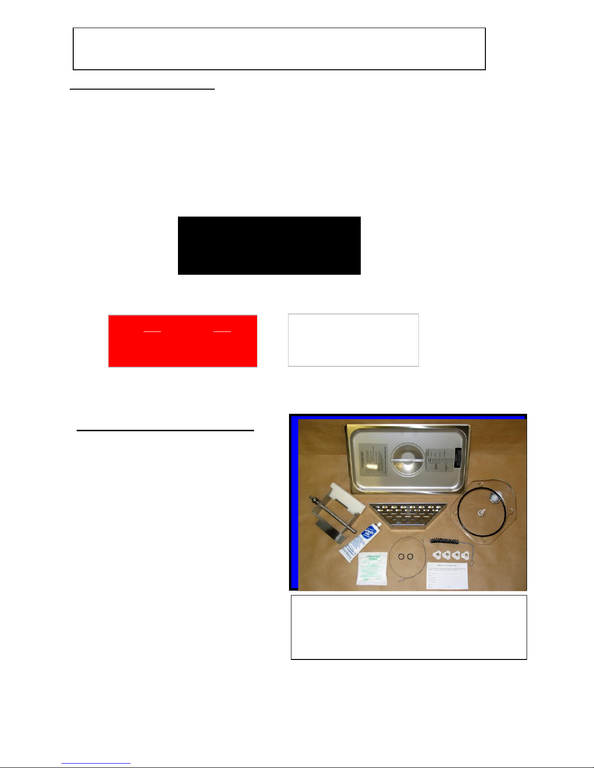
1. Remove the machine from the shipping container.
2. Place the unit on a sturdy platform able to hold the weight of the machine when full of
product. (Usually about 250 lbs.)
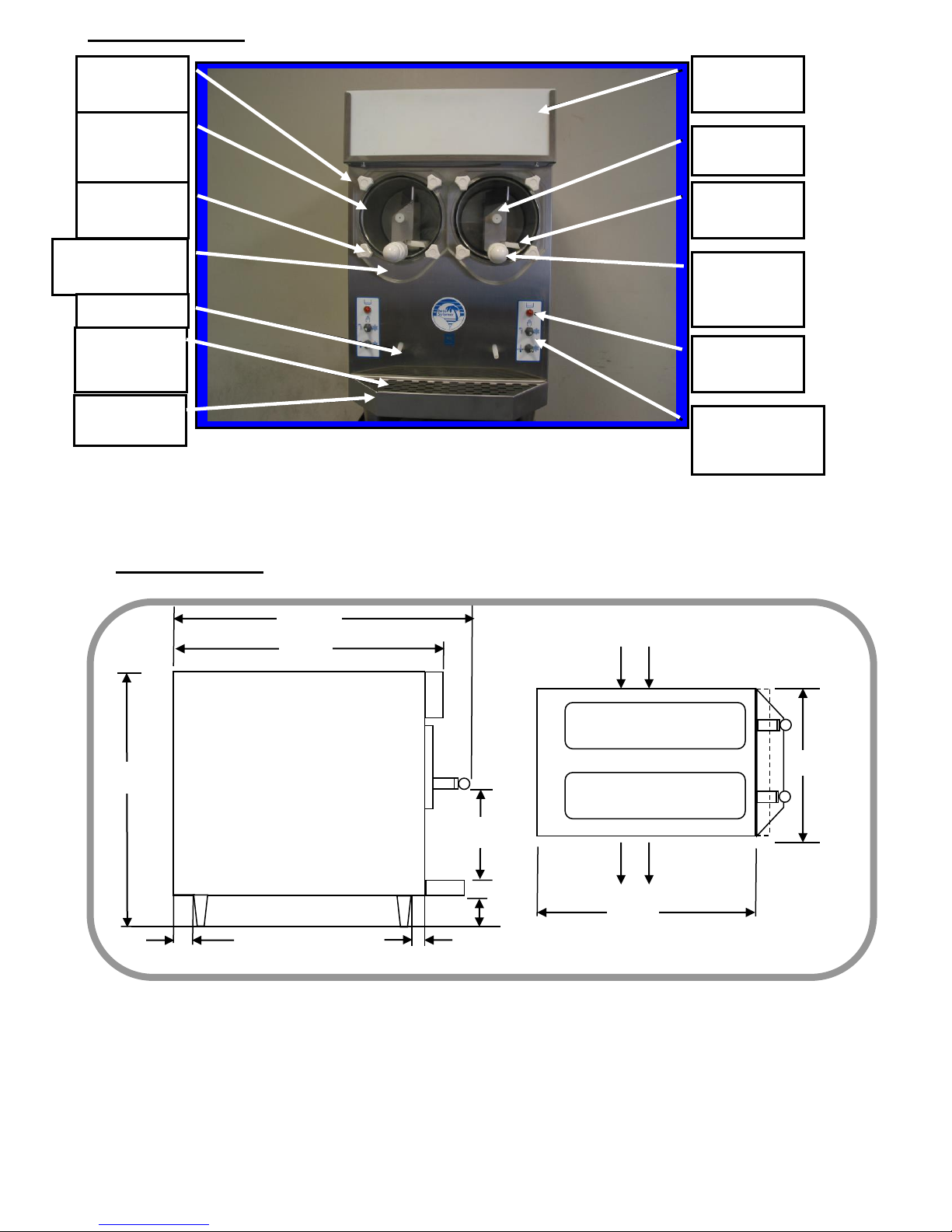
3. Level the machine by turning the adjustable part of the leg. The machine must be level
front to back as well as left to right.
4. Air-cooled condensers must have correct ventilation. Air intake is at the right side of
the machine and discharge through the left side; 8” is required on intake (right) side
and 24” on the exhaust (left) side & 8” clearance restrictions at the back. In addition,
12” clearance above the machine is also required for access.
NOTICE: Locating the unit in direct sunlight, near cooking equipment or any high
heat area will reduce the performance of your machine.
CAUTION: Extended operations under severe heat condition can damage the cooling
system.
NOTICE: Establishments that serve beverages from frozen drink machines are
responsible for providing the necessary facilities for cleaning and
sanitizing their food service equipment.
5. Place the three-position switch in the OFF position (center).
6. Connect the power cord. The Frozen Drink Machine must be connected to a properly
grounded receptacle. The electrical cord furnished as part of the Frozen Drink
Machine has a three prong grounding type plug. The use of an extension cord is not
recommended. If one must be used, refer to the national and local electrical codes.
Do not use an adapter to get around grounding requirements.
SECTION 3
WARNING: Do not
attempt to alter the
electrical plug. Serious
injury or electrocution
may result.
230V
20A
7. Install the drip tray, cover, beater bar and
faceplate assemblies on the machine.
Notice: Your
receptacle
should look
like this.

6
OPERATION
3.1 MACHINE CONTROLS
Two selector switches located on the front of the machine control operation of the Frozen
Drink Machine. Selection of the right (snowflake) position, with both switches, will
schedule the machine for normal operation. The compressor cycle is protected by a time
delay circuit, which will engage the compressor approximately 1 to 2 minutes after
normal operation is initiated. A fill light located above the switches will illuminate when
the level of mix is low in the hopper. A thermostat knob on the electrical control box of
your machine is set at the factory and should not be changed or adjusted except by an
authorized service repairman.
Refer to the information below for functions available with various combinations of
switch positions.
3.2 THE PRODUCT YOU SERVE
Normal Operation –Both switches on
snowflake. Machine will freeze mix to
provide frozen beverage as desired.
Cleaning Operation - The drive
motor will run in the faucet position
to allow a stirring action of the rinse
water while cleaning.
Off - The hand symbol is the
recognized international symbol for
“stop”. In this position,
the machine will not run.
Cooling Operation –Top switch on
snowflake, Bottom switch on
thermometer symbol. Machine will
automatically come on whenever
necessary to keep mix cooled to
5ºC/40ºF - used primarily for
overnight storage of mix remaining
in the machine.
Note:
To turn the flavor light OFF, place both
bottom switches to the left (overnight)
position

7
The Frozen Drink Machine will produce a fine grain, semi-frozen slush when the proper
mix is used. When measured with a refractometer, the proper mix will measure 13 to 18
“brix”. Too little sugar in the mix will cause larger ice crystals to form. Too much sugar
will lengthen the freeze time.
CAUTION: Any attempt to freeze water only will cause severe damage to your
machine.
NOTICE: Do not add sugar directly into the machine, as some of it will settle and
result in an improper mix.
FRUIT JUICES with at least 32 grams of sugar per 8-oz. serving will freeze well in
the Frozen Drink Machine. They will remain stable during the freezing process while
retaining their natural color and flavor.
NEUTRAL BASES are used to produce a neutral frozen cocktail base. A wide variety
of different drinks can be created from one neutral base by the addition of various flavors.
Most brands of neutral bases specify a mixture of four parts water to one part neutral
base. However, before use in the Frozen Drink Machine, be sure the “brix” level is 12 to
18.
The amount of ALCOHOL in the recipe will affect the freezing process. As a rule of
thumb, for the mix to freeze properly, the recipe should contain no more than 25 percent
alcohol.
Suggestion for optimum production and sales:
1) Use the finest ingredients available.
2) Test the product before serving it.
3) Keep the machine clean - ALWAYS!
3.3 PRODUCT CONSISTENCY
3.4 START UP
An exclusive, patented, torque consistency
control (TCC) developed by Frosty Factory of
America will allow for consistent texture and
thickness adjustments of your frozen beverages.
The adjustment screw (accessible through the left
side panel) is pre-set at the factory. Various mix
consistencies can be achieved by turning the
screw clockwise (thicker drink) or counter
clockwise (thinner drink). Turn the screw one
full turn then allow enough time to lapse (about
three minutes) for the compressor to complete a
cycle before sampling. Continue this process
until the desired result is obtained.
Turning the TCC screw clockwise will
make the beverage thicker

8
NOTICE: Before start-up, be sure the machine has been sanitized in accordance
with procedures set forth in the cleaning section of this manual.
Pour the mix into the hopper and allow it to drain into the cylinder.
NOTICE: Always add mix as soon as the red, level indicator light, above the switches,
comes on to prevent air from entering the cylinder.
CAUTION: Allowing air into the cylinder will cause a rocking motion of the machine.
If the mix is not yet frozen the air can escape by turning the machine off for
20-30 seconds.
WARNING:
3.5 FREEZE TIME
The freeze time on the model 217A is approximately 25 minutes with both cylinders
operating. These figures are based on ideal conditions with a starting mix temperature of
approximately 40 degrees and 75 degree air temp. The time will increase if the machine is
not properly ventilated, is operated in a hot environment or the mix is above 40 degrees F.
Some recipes with high alcohol or high sugar content will naturally take a little longer.
SECTION 4
Never under any circumstances,
place your finger or any other object
into the hopper or feed hole while the
machine is in operation. Serious
personal injury may occur.
When the cylinder is full and the hopper is filled to one inch from the top, the machine is
ready to run. Turn on by selecting the “right” (snowflake) position of both switches on
the front panel.
Fill the
Hopper
to about
1 inch
from the
top
Do not run the
machine when
the freezing
cylinder is not
completely full!

9
MAINTENANCE
4.1 CLEANING
The following cleaning procedure should be used for initial start-up and on an as
needed basis to comply with the minimum cleaning and sanitizing frequencies
specified by the federal, state or local regulatory agency having jurisdiction.
(1) Turn the machine to the “OFF” (hand) position, then remove hopper cover.
(2) If applicable, drain mix into a sanitized container as per local health code procedures.
NOTE: Do not put hands or foreign matter into mix.
(3) Pour two gallons of cool water (75ºF) into the hopper. Place upper switch in
“faucet” position to let the machine stir for 2 minutes. Turn machine “OFF”, drain
and dispose of the rinse water. Repeat until water is clear.
NOTICE: Do not unscrew faucet body from faceplate
to clean. (Leak free service after disturbing the Teflon
Seal cannot be assured).
(5) All parts removed during the above steps, plus the drip tray and insert can now be
cleaned in your warm (100ºF) cleaning solution. Rinse all parts in clean rinse water
allow to air-dry before re-assembly.
(6) Use cloth and cleaning solution to wipe any reside from cylinder and hopper.
(7) Re-assemble as shown in section 4.2 (next page).
(8) Mix two gallons of warm water (approximately 100ºF) with two ounces of sanitizing
powder to achieve 100 parts/million (PPM) sanitizing solution.
(9) Pour the sanitizing solution into hopper.
(10) Place upper switch in “faucet” position. Let solution stir for 5 minutes. Turn upper
switch to “OFF” (hand) position. Drain all solution.
(11) Pour product into hopper. Replace hopper cover. Place both switches in right
(snowflake) position when ready to freeze product.
(4) Remove the knobs from the faceplate by turning in
a counter clockwise direction. Carefully pull the
faceplate straight away from the front of the machine.
Remove the beater bar assembly from the cylinder.
Then slide the spring seal off the rear of the beater bar.
Unscrew white faucet cap to remove faucet plunger from
faucet body. Remove all o-rings for cleaning.

10
(5) Mix two gallons of warm water with one 2 oz. packet of sanitizer.
(1) Hand wipe all surfaces to remove any
remaining residue on the machine, then: using
Petro-Gel (or other sanitary food grade lubricant),
lightly lubricate the longer end of the beater shaft.
Slide beater seal onto the shaft with the spring end
toward the beater bar. (Refer to diagram on top of
the hopper cover for correct installation of spring
seal).
NOTICE: The black carbon ring must be
facing the end of the beater bar so it will be
in direct contact with the white ceramic seal
inside the cylinder when the beater bar is re-
installed. This is a dry seal and must be
kept free of lubricants.
CAUTION: The beater seal may become
damaged if the beater shaft is not
lubricated before installation of the beater
seal.
(2) Carefully insert the beater bar (with beater
seal) into hole at the rear of the cylinder
and rotate until it fully engages into the
drive plate.
CAUTION: Do not strike the
ceramic seal with the beater bar
during installation!
(3) Lubricate the large, black, rubber, faceplate
O-ring with Petro-Gel then re-install and
press firmly into the faceplate groove for
proper fit. Re-install o-rings on faucet
(4) Re-install the faceplate on the machine.
First place the faceplate bushing onto
the beater shaft. Then slide face plate
onto the four studs. Now re-attach the
faceplate knobs and tighten evenly until
the faceplate O-ring is snug against the
cylinder. Re-install float and float clip.
CAUTION: Do not over tighten the knobs
or tighten against a beater bar that is not
fully engaged in the drive plate; Permanent
distortion to the faceplate may occur!
4.2 RE-ASSEMBLY
F0298
F0355
C6519
C6521
C6513

11
(6) Pour two gallons of solution into hopper. Clean the hopper and feed hole with a clean
sanitized brush.
(7) Place upper switch in “faucet” position. Let solution stir for 5 minutes. Turn upper
switch “OFF” (hand position), Drain all solution. (DO NOT RINSE!)
(8) Pour product into hopper. Replace hopper cover. Place both switches in right
(snowflake) position when ready to freeze product.
4.3 PREVENTATIVE MAINTENANCE
It is recommended that a maintenance schedule be followed to keep the machine clean
and operating properly.
WARNING: never attempt to repair or perform maintenance on machine until the main
electrical power has been disconnected.
A. DAILY
The exterior of the machine should be kept clean at all times to preserve the luster of
the stainless steel. A mild alkaline cleaner is recommended. Use a soft cloth or
sponge to apply the cleaner.
B. WEEKLY
(1) Check O-rings and rear seal for excessive wear and replace if necessary.
(2) Clean the drip tray and front of the freezer with a soap solution.
C. MONTHLY
CAUTION: Air-cooled condensers must have proper air circulation. Failure to clean
the condenser on a regular basis may result in serious damage and could
void the warranty.
(1) Visually inspect the condenser for dirt by shining a light through the coil from the
inside of the condenser.
(2) If the condenser is dirty, place a wet towel over the outside of the condenser.
(3) Using compressed air or a CO2 tank, blow out the dirt from the inside of the
condenser. Most of the dirt will cling to the wet towel.
(4) An alternative method of cleaning the condenser is to use a condenser brush and
vacuum.
NOTICE: If the condenser is not kept clean, loss of refrigeration efficiency will
result, causing extended run time or soft product consistency.
4.4 EXTENDED STORAGE
Refer to the following steps for storage of the machine over any long shutdown period:
(1) Turn the three position switch to the OFF (center) position.
(2) Disconnect (unplug) from the electrical supply source.
(3) Clean thoroughly with a warm detergent all parts that come in contact with the mix.
Rinse in clean water and dry all parts. Do not sanitize. Machine parts can be left
disassembled until ready for use.
NOTICE: Do not let the cleaning solution stand in the hopper or in the cylinder during
the shutdown period.
4.5 TROUBLESHOOTING

12
1. Machine does not run when turned on.
A. Be sure that the cord is properly plugged into a wall outlet.
B. Check and reset circuit breaker (in the building) if necessary.
C. Be sure that no other appliances are sharing the circuit.
D. If problem remains, call service repairman.
E. Face plates are removed or face-plate interlock sensor is misaligned with face plate magnet.
2. Beater motor starts but compressor doesn’t start.
A. Both switches must be in the right (Snowflake) position.
B. Allow approximately one or two minutes for time delay to respond.
C. Check that the machine has been properly leveled.
D. If necessary adjust TCC screw.
E. Have the machined checked to see if it is low on refrigerant.
3. Mix dripping from drip tube.
A. Spring seal on beater bar is dirty or improperly installed. Remove, clean and re-install spring seal
assembly according to instructions and diagram on top of the hopper cover.
B. Ceramic seal (inside the freezing cylinder) is dirty or loose. Clean ceramic seal. If loose re-install
as necessary. Also check that the carbon ring on the seal is not chipped, cracked, dirty or greasy.
Replace seal if necessary.
4. Unit runs but product does not freeze to desired consistency.
A. Check recipe for proper amount of sugar(13-18 Brix)
B. Check tension of TCC screw, if necessary turn clockwise to increase thickness of drink.
C. Check unit for adequate ventilation. (At least 6” clearance required on the right side and 12” on the
left side with no clearance restrictions at the rear).
D. Check the condenser to see if it has become clogged with lint, dust etc. Clean as necessary.
E. Be sure that the cylinder is full of mix.
F. Fill a cup with beverage and check the temperature. If the temperature is below 28 degrees F. there
may be too much alcohol in the recipe.
5. Fill light is on when hopper is full of product.
A. Remove and re-install float with two dots facing up. (See pg. 16)
B. If float is stuck, clean float and stem and re-assemble.
6. No product comes out when faucet handle is pulled while unit is running.
A. Frozen product is blocking “feed hole”. Turn machine off then clear ice plug from feed hole.
WARNING: Never place fingers in the “feed hole” as serious personal injury
may occur.
B. Mix is frozen solid. Low sugar content, product separation or cylinder not full.
7. Compressor starts and stops intermittently.
A. Check to see that the fan is turning freely.
B. Check the condenser to be sure that it is not clogged with lint or dust.
C. Check recipe for correct sugar level (13-18 Brix).
D. If the on/off time is 30 seconds or longer, this is normal if product is frozen and no product has
been pulled in a while
8. Unit continues to run when switched to stand-by.

13
A. Remove back panel and reset thermostat. (Turn all the way off then turn all the way on again.)
B. If problem remains replace thermostat.
9. Beater bar does not turn.
A. Mix is frozen solid. Low sugar content, product separation or cylinder not full.
B. Drive coupling stripped. Drive coupling needs to be replaced
C. Faulty motor. Replace motor
10. Mix turns grey or pitting metal in the freezing barrel.
A. Too much chlorine in sanitizing solution: Follow directions on product package to get 100
parts/million chlorine solution. Stir this solution in the machine for 1-2 minutes only and then drain
completely.
DO NOT ALLOW SANITIZING SOLUTION TO SIT IN THE MACHINE
FOR ANY REASON!!! If the barrel becomes saturated with chlorine, apply
chlorine neutralizer as needed to remove (obtain from swimming pool supply
store).

14
4.6 REAR CYLINDER AND DRIVE ASSEMBLY PARTS LIST
Models 217A.
1 2 3 4 5 6 7 8 9
blk to “sw 1”white to run cap.
red to run cap w/neutral
10 11 12 13 14 15
DESCRIPTION PART NUMBER_____________________
1. Seal, Ceramic Ring ½” F0665
2. Bearing Spacer Block C2316B
3. Front Motor Bearing F0427
4. Flat Washer 5/16”
5. Nut 5/16”-18
6. Drive Coupling C0906
7. Stop Bolt Assembly 1/4”-20x11/4”
8. Mercury Switch F0752
9. Drive Motor 115V F0472
Gear Box F5125
10. C-Bracket F1206
11. C-Bracket Stub C1207
12. Rear Support Bearing F0479
13. Rear Bearing Carrier C1216
14. Rear Cross Brace F2003
15. Frame Screw 5/16”-18 x ¾”

15
4.7 TORQUE CONSISTENCY CONTROL MODEL 217A
1 2 3 4 5 6 7 8 9 10 11
Wires to control circuit
DESCRIPTION PART NUMBER ____________
1. Washer, Flat 5/16”
2. Tension Adj. Screw ¼”-20x3”
3. Motor Adjustment Bracket F1225
4. Tension Spring F0432
5. Lock Nut ¼”-20
6. Motor Spring Bracket F1239
7. Mercury Switch Assembly F0752
8. Drive Coupling C0906
9. Drive Motor(115V) F0472
-- Drive Motor(230V) F0415
10. Front Cross Brace F2002
11. Frame Screw 5/16”-18x1/2”
Notice: Items numbered 9 through 12 are not part of the torque consistency control
system, but are listed for user convenience.

16
4.8 FACEPLATE / FAUCET ASSEMBLY
Faucet Assembly C6513.
Teflon Tape added
before installation
Lubricating
O-rings with
Petro-Gel
F0298
Installing Plunger
assembly C6513P
into faucet body
Installing faceplate C6521
onto front of Machine.
Installing
O-rings onto
plunger
F 0491
Align Faucet Assembly opening to
bottom of faceplate then tighten nut

17
4.8 FACEPLATE/FAUCET ASSEMBLY
Face Plate/Faucet Assembly Part No.
A. Face plate assembly with magnet C6521
B. Faucet assembly with nut C6513
C. Plunger Assembly (only) C6513P
D. Faucet body (only) C6513B
Plunger Assembly C6513P
Knob O-Rings Face Plate
F0264 F0491 C6521
O-Ring
F0357
F.P. Bushing
C6520
Faucet Body Faucet Nut
C6513B F0197
*Magnet
Add Teflon Tape
*Motor Disconnect Magnet (Motor will not operate when faceplate is removed)

18
4.9 FLOAT SWITCH ASSEMBLY
1. The float switch assembly consists of: Post switch, Float , Float clip, O-Ring
and Nut.
2. There are two dots on one end of the float. When assembled the two dots must
be on the top end of the float.
3. Place O Ring so that it will be inside the hopper (sink bottom) when finished.
Clip
Fill Switch Assembly F0811 Raised Ring must point up
Bottom of hopper Float
Hex shape for back-up wrench
O-Ring
Nut
Two wires from float switch to control circuit.
Top View of Float Switch
Two Dots or Raised Ring (Up)
Float Clip F0812
Post
4.9a THERMOSTAT ASSEMBLY
L1 To upper switch
F0401
2 pos. switch T-Stat

19
4.10 USING THE CLEANING BRUSHES
Drip Chamber
Ceramic Seal
Cylinder
Warm Water
Drip Tube
Drip tube Brush
F6526 Drain Spacer Block
C2316B
Insert long brush
F6526 into drip tube
Push brush all the way in
until it can be seen in the
middle of the ceramic ring

20
4.11 BEATER BAR AND SPRING INSTALLATION
.
Step 1: Attach scraper
blade spring F6517as
shown.
Step 2: Insert rod
end into beater bar
frame.
Step 4: Apply and
smear a small dab of
Petro-Gel F0298 on the
shaft end
Step 3: Tap scraper
blade rod until it is
centered.
Step 5: Install spring
seal F0355
Step 6: Squeeze and
release spring. Be
sure the spring
returns to normal
before installing into
machine.
Step 8: Install
faceplate C6521
onto machine
Step 7: Install
beater bar C6519
into cylinder.
Table of contents
Popular Freezer manuals by other brands

Matrix
Matrix MFU801 Manual for installation, use and maintenance

Electrolux
Electrolux LUT9ME28X4 user manual

Whirlpool
Whirlpool AFB 835/A Instructions for use

Continental Refrigerator
Continental Refrigerator CFB42 Specifications

Leonard
Leonard LKG1843 user manual

Marvel
Marvel MS24FA Installation, operation and maintenance instructions

Bosch
Bosch GID18A20GB operating instructions

Frigidaire
Frigidaire FFU20F9HW3 Service data sheet

HAEGER
HAEGER CF-300.002A instruction manual

Campomatic
Campomatic CHC12 instruction manual

Vector
Vector Deluxe Console VEC223F Owner's manual & warranty information

GE
GE FUM14SVR Dimensions and installation information