Frox FroxSystem User manual

Frox,
Inc.,
323
Sinclair
Frontage
Road,
Milpitas,
CA
95035
408.957.7420
FAX
408
.946
.3657
Frox
Technical
Support
may
be
contacted
at
800
.525
.5257
during
the
hours
of
8:30AM
to
5:00PM
PST,
Monday·
Friday

INSTALLATION
GUIDE
-
Saftey
Precautions
--~«««««««««««««««««<
CAUTION: TO REDUCE THE RISK OF ELECTRIC SHOCK,
DO NOT REMOVE COVER (OR BACK)
NO USER-SERVICEABLE PARTS INSIDE
REFER SERVICING TO QUALIFIED SERVICE PERSONNEL.
The
lightning
flash
with
arrowhead
symbol,
within
an
equilateral
triangle,
is
intended
to
alert
the
user
to
the
presence
of
uninsulated
'dangerous
voltage'
within
the
product's
enclosure
that
may
be
of
sufficient
magnitude
to
constitute a
risk
of
electric
shock.
The
exclamation
point
within
an
equilateral
triangle
is
in-
tended
to
alert
the
user
to
the
presence
of
important
op-
eration
and
maintenance
(servicing)
instructions
in
the
literature
accompanying
the
appliance
..

INSTALLATION
GUIDE
-
Saftey
Precautions
IMPORTANT
SAFEGUARDS
Thank
you
for
selecting
the
FroxSystem
horne
entertainment theater
ensemble!
We
hope
your
entertainment
experience
is
enriched
by
our
state-of-the-art
digital
audio/video
imaging
and
information
management
systems.
Please
READ
TIIESE
INSTRUCTIONS
CAREFULLY
concerning safe operation ofyour system, and retain this
manual for future reference.
Use
this
space
to
record
your
component(s)
serial
numbers
for
future
reference:
Model
Numbers
Serial
Numbers
Model
Numbers
Serial
Numbers
WARNING:
TO
PREVENT
FIRE
OR
SHOCK
HAZARD,
DO
NOT
EXPOSE
THIS
APPUANCE
TO
RAIN
OR
MOISTIJRE.
CAUl10N:
TO
PREVENT
ELECfRIC
SHOCK,
DO
NOT
USE
TIllS
POLARIZED
OR
THREE-WIRE
GROUNDING
PLUG
wrrn
AN
EXfENSION
CORD,
RECEPTACLE
OR
OTHER
OUTIET
UNLESS
THE
BLADES
CAN
BE
FUllY
INSERTED
TO
PREVENT
BLADE
EXPOSURE.
NOTE
TO
CAlV
SYSTEM
INSTALLER:
THIS
REMINDER
IS
PROVIDED
TO
CALL
THE
CATV
SYSTEM
INSTALLER'S
ATfENTION
TO
ARTICLE
820-33
OF
THE
NEC
THAT
PROVIDES
GUIDELINES
FOR
PROPER
GROUNDING.
IN
PARTICULAR,
THIS
SPECIFIES
THAT
THE
CABLE
GROUND
SHAll
BE
CONNECTED
TO
THE
GROUNDING
SYSTEM
OF
THE
BunnING
AS
CLOSE
TO
THE
POINT
OF
CABLE
ENTRY
AS
PRACTICAL.
3

4
INSTALLATION
GUIDE
-
Saftey
Precautions
IMPORTANT
SAFEGUARDS
o (1) Read, Follow
and
Retain all Instructions and
Warnings.
Read
and
follow
all
the
safety
and
operational
instructions
before
using
your
FroxSystem,
and
retain
these
instructions
for
future
reference.
All
warnings
on
the
components
and
within
the
Owner's
Manual
should
be
carefully
adhered
to.
Please
review
and
follow
all
specific
operation
and
usage
instructions
as
outlined
within
this
Owner's
Manual.
o(2) Water and Moisture.
To
prevent
fire
or
electrical
shock,
do
not
expose
the
Frox
components
to
water
or
moisture.
Do
not
set
or
use
these
components
near
water
(for
example,
near
a
sink
or
wash
tub,
in
a
wet
basement,
etc.).
Use
extreme
care
with
any
liquids
near
any
electronic
components.
o (3) Cabinet Care and Cleaning.
Always
unplug
your
FroxSystem
from
the
wall
outlet
before
cleaning.
Use
only
a
damp
cloth
for
cabinet
cleaning;
wipe
dry.
A
mild
detergent
can
be
applied
to
a
moistened
cloth
for
heaver
cleaning
needs.
Never
use
any
petroleum-based
liquid
or
aerosol
cleaners.
o (4) Placement
and
Mounting.
Never
place
the
Frox
components
on
an
unstable
stand,
table,
cart,
bracket
or
the
like.
A
cart
or
stand
may
fall,
resulting
in
serious
injury
to
an
adult
or
child
and
damage
to
the
components.
Use
care
when
moving
any
component
and
cart
combination,
as
uneven
surfaces,
quick
starts
and
stops,
even
excessive
force
may
cause
the
cart
to
overturn.
Use
only
on
a
stand,
table,
or
cart
recommended
by
the
cart
manufacturer
or
Frox.
Do
not
place
heavy
objects
on
top
of
the
Frox
components
as
damage
may
result.
Finally,
use
care
in
mounting
any
of
the
system
components;
follow
all
specific
installation
instructions,
heed
all
mounting
safety
warnings
and
only
use
recommended
mounting
accessories
(where
applicable).
0(5)
Attachments.
Attachments
other
than
those
recommended
by
Frox
may
cause
hazards.
Do
not
use
any
other
attachments
or
devices
to
these
components
without
the
manufacturer's
approval.
o (6) Ventilation.
Your
components
are
designed
with
optimum
ventilation
for
reliable
operation
and
protection
from
overheating.
Maximum
ventilation
occurs
when
placed
on
hard,
flat

INSTALLATION
GUIDE
-
Acknowledgments
surfaces.
Special
cabinet
slots
assisting
in
ventilation
must
never
be
blocked
by
placing
the
components
on
a
bed,
sofa,
rug
(and
any
other
like
materials)
or
other
components.
Never
allow
drapes,
rugs
or
other
coverings
to
block
any
of
the
component
vents.
Always
establish
proper
component
spacing
when
installing
the
Frox
components
into
a
bookshelf
or
component
rack
Also,
insure
that
the
electronics
are
kept
away
from
heat
sources
(radiators,
heating
ducts)
that
may
cause
damage
to
the
system
components.
o (7) Power Sources.
The
Frox
components
are
intended
to
operate
only
from
power
sources
listed
on
the
marked
label
on
the
compo-
nents.
Consult
your
Frox
dealer
or
your
local
power
company
if
you
are
unsure
of
the
specific
type
of
power
supplied
to
your
home.
For
video
products
intended
to
operate
from
battery
power,
or
from
other
sources,
refer
to
the
operating
instructions.
o (8) Power Cords, Plugs and Grounding.
Your
components
are
equipped
with
a
three-wire
Ground-
ing-type
plug
for
your
safety:
Three-wire Grounding-type Plugs - a
plug
with
a
third
(grounding)
pin.
This
plug
will
only
fit
into
a
grounding-
type
power
outlet.
This
is
a
safety
feature.
If
you
are
unable
to
insert
the
plug
into
the
outlet,
contact
your
electrician
to
replace
your
obsolete
outlet.
Do
not
defeat
the
safety
purpose
of
the
grounding-type
plug.
To
prevent
the
risk
of
fire
or
electric
shock,
never
overload
wall
outlets
and/or
extension
cords.
Frox recommends
the use of a safety-fused, properly-grounded regu-
lated power strip
or
recepticle for optimum compo-
nent protection.
Finally,
protect
your
power
supply
cords.
Always
route
power
cords
with
care
to
minimize
fire
or
shock
hazards.
Insure
that
power
cords
are
never
walked
upon,
crimped
or
pinched
by
any
furniture
placed
upon
or
near
them,
component
positioning
against
the
wall,
etc.
Pay
particular
attention
to
cords
at
plugs,
convenience
recepticles
and
the
point
where
they
exit
from
the
component(s).
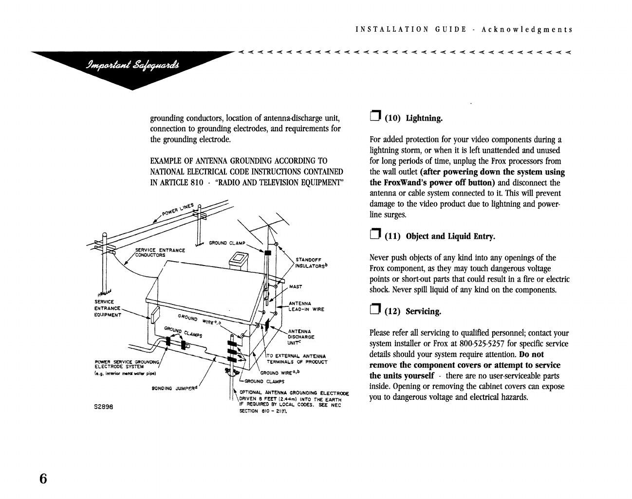
o(9) Outside Antenna Systems -Safety and
Grounding.
Use
extreme
care
when
installing
an
outside
antenna
system.
Never
locate
an
outside
antenna
system
near
overhead
power
lines,
overhead
lights
or
any
other
powered
circuits,
particularly
if
the
antenna
could
fall
and
come
into
contact
with
the
power
lines
or
circuits.
When
installing
an
outside
antenna
system,
extreme
care
should
be
taken
to
keep
from
touching
any
power
lines
or
circuits
-
contact
with
them
might
be
fatal.
If
you
use
an
outside
antenna
or
cable
system,
insure
that
the
antenna
or
cable
system
is
properly
grounded
to
protect
from
unwanted
voltage
surges
or
built-up
static
charges.
Section
810
of
the
National
Electric
Code,
ANSIjNFPA
No.
70
-
1984,
provides
information
with
respect
to
proper
grounding
of
the
mast
and
supporting
structure,
grounding
of
the
lead-in
wire
to
an
antenna-discharge
unit,
size
of
5

6
EQUIPMENT
grounding
conductors,
location
of
antenna-discharge
unit,
connection
to
grounding
electrodes,
and
requirements
for
the
grounding
electrode.
EXAMPLE
OF
ANTENNA
GROUNDING
ACCORDING
TO
NATIONAL
ELECTRICAL
CODE
INSTRUCTIONS
CONTAINED
IN
ARTICLE
810
-
"RADIO
AND
TELEVISION
EQUIPMENT"
STANDOFF
INSULATORSb
LEAO-IN
WIRE
ANTENNA
DISCHARGE
UNI'T"
TO
EXTERNAL ANTENNA
Te:RMINA~S
OF
PROOUCT
(e.g.
imtriOt
mata
waf.,.
pipe)
SONCING
JUMPEAd
S289B
\QI'TIONAL AIITENNA
GROUNOIP-IG
ELECTRODE
DRIVEN
e FEET
(Z.44m)
INTO
THE
EARTH
IF
REQUIRED
B'r
!.DCAI.
COOES.
SEE
NEC
SECTION
810 -ZI (f).
INSTALLATION
GUIDE
-
Acknowledgments
o(10)
Lightning.
For
added
protection
for
your
video
components
during
a
lightning
storm,
or
when
it
is
left
unattended
and
unused
for
long
periods
of
time,
unplug
the
Frox
processors
from
the
wall
outlet
(after
powering
down
the
system using
the
FroxWand's
power
off
button)
and
disconnect
the
antenna
or
cable
system
connected
to
it.
This
will
prevent
damage
to
the
video
product
due
to
lightning
and
power-
line
surges.
o(11)
Object
and
Liquid
Entry.
Never
push
objects
of
any
kind
into
any
openings
of
the
Frox
component,
as
they
may
touch
dangerous
voltage
points
or
short-out
parts
that
could
result
in
a
fire
or
electric
shock.
Never
spill
liquid
of
any
kind
on
the
components.
o(12)
Servicing.
Please
refer
all
servicing
to
qualified
personnel;
contact
your
system
installer
or
Frox
at
800-525-5257
for
specific
service
details
should
your
system
require
attention.
Do
not
remove
the
component
covers
or
attempt
to
service
the
units
yourself -
there
are
no
user-serviceable
parts
inside.
Opening
or
removing
the
cabinet
covers
can
expose
you
to
dangerous
voltage
and
electrical
hazards.

INSTALLATION
GUIDE
-
Saftey
Precautions
o (13) Damage Requiring Service.
Inunediate1y
disconnect
the
components
from
the
power
source
and
contact
your
qualified
service
personnel
should
one
of
the
following
conditions
occur:
(a)
Any
liquid
has
spilled
in/on
the
components
(b)
Any
object
has
fallen
into
the
components.
(c)
A
heavy
object
has
fallen
onto
the
components
(d)
Any
Frox
component
has
been
dropped
and/or
exhibits
cabinet
damage
(e)
Whenever
the
power
cord
and/or
plug
has
been
damaged
(t)
The
products
have
been
exposed
to
rain
or
other
elements
(g)
If
the
product
exhibits
a
distinct
change
in
performance;
this
indicates
a
need
for
service
(h)
Your
product
does
not
appear
to
operate
normally
by
following
these
operation
instructions
within
the
Owner's
Manual.
Adjust
only
those
controls
covered
by
the
operating
instructions,
as
improper
adjustment
of
other
controls
may
result
in
damage
and
will
often
require
extensive
work
by
a
qualified
technician
to
restore
the
product
to
its
normal
operation.
o (14) Replacement Parts.
When
replacement
parts
are
required,
be
sure
the
service
technician
has
used
replacement
parts
specified
by
the
manufacturer
or
have
the
same
characteristics
as
the
original
part.
Unauthorized
substitutions
may
result
in
fire,
electric
shock
or
other
hazards.
o (15) Safety Check.
Upon
completion
of
any
service
or
repairs
to
this
product,
ask
the
service
technician
to
perform
safety
checks
to
determine
that
the
product
is
in
proper
operating
condition.
7

8
INSTALLATION
GUIDE
-
Saftey
Precautions
o(16)
Software
Authorizations.
CAlITION:
Any
changes
or
modifications
to
the
operating
software,
design,
recommendations
and
electronic
component(s)
not
expressly
authorized
and
approved
by
Frox,
Inc.
in
writing
will
void
the
specific
user's
authority
to
operate
the
equipment.
See
your
component
warranty
for
further
details.
o(17)
FCC
Class
8
Digital
Device
Compliance.
NOTE:
This
equipment
has
been
tested
and
found
to
comply
with
the
limits
for
a
Class
B
digital
device,
pursuant
to
Part
15
of
the
FCC
Rules.
These
limits
are
designed
to
provide
reasonable
protection
against
harmful
interference
in
a
residential
installation.
This
equipment
generates,
uses
and
can
radiate
radio
frequency
energy
and,
if
not
installed
and
used
in
accor-
dance
with
the
instructions,
may
cause
harmful
interference
to
radio
communications.
However,
there
is
no
guarantee
that
interference
will
not
occur
in
a
particular
installation.
If
this
equipment
does
cause
harmful
interference
to
radio
or
television
reception,
which
can
be
determined
by
turning
the
equipment
off
and
on,
the
user
is
encouraged
to
try
to
correct
the
interference
by
one
or
more
of
the
following
measures:
~
Reorient
or
relocate
the
receiving
antenna.
~
Increase
the
separation
between
the
equipment
and
receiver.
~
Connect
the
equipment
into
an
outlet
on
a
circuit
different
from
that
to
which
the
receiver
is
connected.
~
Consult
an
experienced
radio/fV
technician
for
help.

INSTALLATION
GUIDE·
Table
of
Contents
Important Safeguards...2
Introduction
Purpose
of
the Manual...ll
Using
the
Manual...12
Planning a Successful Installation
...
15
Environmental
and
Electrical
Considerations
...
16
Upgrading to V3.0 and Beyond
Frox
CD
Booting
Utility
...
19
Hardware Installation
Getting
Started
...
25
Connecting
the
Media
Processor
and
the
Video
Preprocessor
...
29
Monitor
Connection
...
31
TV
Signals
..
.3
7
CD
Players
...
41
Time
Base
Correctors
...
43
VCRs
...
45
Laserdisc
Players
...
49
Speakers
...
51
Miscellaneous
Analog
Audio
Devices
...
55
IR
Emitters
..
.5
7
IR
Repeaters
...
59
Using
X·IO
Modules
...
61
Multiroom
Audio
...
62
Software Installation
Getting
Started
...
63
Preferences
...
64
Authorizations
...
67
Locale,
Date
and
Time
...
69
TV
Channels
...
71
TV
Signals
...
75
VCRs
...
79
Laserdisc
Players
...
83
CD
Players
...
85
Miscellaneous
Analog
Audio
Devices
...
89
Speakers
...
91
Alternate
Monitor
...
97
Maintenance
Save
Setup
...
l0l
Restore
Setup
...
l02
System
Update
...
l02
CD
Covers
...
l02
Convergence
...
104
UI
Shifting
...
l05
Statistics
...
106
Troubleshooting
...
l09
Appendices
...
I13
Appendix
A.
General
Electrostatic
Procedures
Appendix
B.
Sync
Jumper
Appendix
C.
DSP
Audio
Cards
Appendix
D.
Learn
Mode
Scripts
9

10
ACKNOWLEDGMENTS
Frox,
FroxSystem,
FroxVision,
FroxSound,
FroxControl,
FroxWand,
FroxRoute,
FroxZone,
Active
Pixel
Control,
Sonic
Playground
and
Digital
Straight
Line
are
all
trademarks
of
Frox,
Inc.
FroxCast
is
a
servicemark
of
Frox,
Inc.
All
rights
reserved.
Portions
of
the
FroxSystem
products
have
been
licensed
from
Adobe
Systems
Incorporated,
Bradley
Forthware
and
Rairna
Corporation.
INSTALLATION
GUIDE·
Acknowledgments
The
Frox
DolbyTM
Pro·
Logic
processing
is
manufactured
under
license
from
Dolby
Laboratories
LicenSing
Corpora·
tion.
Additionally
licensed
under
one
or
more
of
the
following
patents:
U.S.
numbers
3,632,886,
3,746,792
and
3,959.590;
Canadian
numbers
1,004,603, 1,037,877.
"Dolby"
and
the
double·D
symbol
are
trademarks
of
Dolby
Laboratories
Licensing
Corporation.
All
rights
reserved.
The
Frox
Horne
THX®
Audio
System
is
manufactured
under
license
from
LucasArts
Entertairnnent
Company.
THX
is
a
registered
trademark
of
LucasArts
Entertainment
Company.
All
rights
reserved.

INSTALLATION
GUIDE·
Introduction
The
FroxSystem
Installation
Manual
is
intended
to
be
a
simple
navigation
guide
through a
FroxSystem
installa·
tion.
Along
the
way,
many
useful
facts
and
hints
are
provided that
should
reduce
the
chance
of
error.
It
is
a
good
idea
to
read the entire installation
manual
as
if
is
was
a
novel.
As
the
FroxSystem
is
an
integrated
platform
combining
audio,
videoand sophisticated
computer
technologies,
all
installation
topics
are
very
much
related
and
should
be
understood prior
to
attempting
any
installation.
o A
numeric
"checkbox"
format
has
been
used
that
allows
the installer
to
mark
off
completed
steps.
Installation notes
may
be
written
directly
on
each
page
in
the
margins
prOvided.
11

12
USING
TIllS
MANUAL
The
FroxSystem
Installation
Manual
is
designed
to
walk
an
installer
through
the
planning
stages
of
an
installation
to
the
moment
the
system
is
ready
for
operation.
The
manual
should
be
closely
observed
from
beginning
to
the
end.
The
"Hardware"
chapter
should
always
be
completed
before
the
"Software"
chapter
is
initiated
to
avoid
potential
hazards.
A
"Troubleshooting"
section
provides
a
quick
reference
for
common
installation
problems;
several
appendices
are
included
for
miscellaneous
hardware
and
software
issues
requiring
more
detailed
explanations.
In
the
information
packet
shipped
with
each
Media
Processor
and
Video
Preprocessor
there
are
rear
panel
diagrams
of
each
component.
These
are
to
be
used
during
the
"Hard-
ware"
installation
chapters
to
notate
what
is
connected
to
each
port.
This
will
be
helpful
later
when
going
through
the
"Software"
installation
procedure.
It
is
strongly
recom-
mended
that
these
charts
be
completed
and
used
when
attempting
a
FroxSystem
installation.
Since
the
system
integrates
a
multitude
of
products
it
is
important
to
keep
track
of
hardware
connections.
(The
rear
panel
diagrams
for
both
the
Media
Processor
and
Video
Preprocessor
are
also
located
in
the
Preparation
section
of
the
"Hardware"
installation
chapter).
In
this
manual,
several
graphic
and
textual
conventions
are
used
to
simplify
the
understanding
of
procedures
and
words.
For
example,
button
names
are
in
all-caps
as
illustrated
in
the
sentence
-
To
change
the
FroxWand
speed,
click
on
the
FROX
button
to
access
the
Frox
"Go-To"
menu
and
then
INSTALLATION
GUIDE
-
Introdnction
click
on
the
PREFERENCES
button
...
In
this
sentence
both
"FROX"
and
"PREFERENCES"
are
button
names.
Note
that
the
words
"click
on"
refer
to
squeezing
and
releasing
the
activation
triggers
on
the
FroxWand.
Other
important
topics
are
indicated
by
the
capitalization
of
the
first
letter
in
each
word
describing
each
respective
screen,
area
or
control
panel.
For
example
in
the
sentence
-
If
the
VCR
button
does
not
appear
on
the
Video
Control
Stripe
then
re-enter
Installation
and
re-install
the
VCR.
In
this
sentence
both
''Video
Control
Stripe"
and
"Installation"
conform
to
the
defined
rules.
In
the
"Software"
Installation
procedure
various
buttons
provide
functions
that
help
an
installer
move
through
screens
(or
scroll
through
lists).
Here
are
some
button
deSCriptions
that
are
useful
to
know:
NEXT
The
NEXT
button
is
found
on
the
Installa-
tion
Control
Stripe.
It
is
used
to
move
forward
in
a
particular
area
of
Installation.
For
example,
when
installing
Analog
Audio/Video
components,
the
NEXT
button
will
scroll
for-
ward
to
relevant
installation
screens.
Depending
upon
what
the
system
already
knows
it
mayor
may
not
access
every
installation
screen
in
a
particular
area.
For
example,
if
no
device
is
installed
in
Video
In
2,
a
NEXT
selection
will
scroll
directly
to
Aux
In
1
instead
of
landing
on
each
of
the
instal-
lation
screens
associated
with
Video
In
2.

INSTALLATION
GUIDE
-
Introduction
The
NEXT
button
will
not
scroll
from
section
to
section.
At
the
end
of
a
particular
installation
section,
a
NEXT
selection
will
not
introduce
any
new
screen.
To
get
to
a
different
installation
section,
select
the
appropriate
new
topic
button
from
the
Installation
Control
Stripe.
PREY
The
PREY
button
is
found
on
the
Installa-
tion
Control
Stripe.
It
is
used
to
scroll
backward
in
a
particular
area
of
Installa-
tion.
For
example,
when
installing
Analog
Audio/Video
components,
the
PREV
button
will
move
backward
to
relevant
installation
screens.
Depending
on
what
the
system
already
knows
it
mayor
may
not
access
every
installation
screen
in
a
particular
area.
For
example,
if
no
device
is
installed
in
Video
In
2,
a
PREY
selection
from
the
Aux
In
1
installation
screen
will
scroll
directly
to
Video
In
2
instead
of
landing
on
each
of
the
installation
screens
associated
with
Video
In
2.
The
PREY
button
will
not
scroll
from
section
to
section.
At
the
beginning
of
a
particular
installation
section,
a
PREY
selection
will
not
introduce
any
new
screen.
To
get
to
a
different
installation
section,
select
the
appropriate
button
from
the
Installation
Control
Stripe_
SCROLL
BARS
Scroll
Bars
can
be
found
adjacent
to
lists
that
extend
to
another
page
of
information.
They
are
commonly
found
at
the
bottom
of
device
lists
and
television
channels
lists.
The
Frox
"Go-To"
menu
offers
another
example
of
Scroll
Bars
in
the
FroxSystem.
DONE
§
The
DONE
button
is
found
on
the
Installa-
I Done I
tion
Control
Stripe.
It
is
used
to
exit
the
Installation
procedure
and
save
all
changes
to
the
installa-
tion
configuration
that
were
made.
This
procedure
can
take
up
to
30
seconds.
While
this
is
occuring
the
message
"Com-
pleting
Installation
....
One
moment
please"
will
notify
you
of
the
system's
status.
When
the
data
is
saved,
the
message
"Installation
completed
successfully"
will
briefly
be
written
to
the
screen,
followed
by
the
drawing
of
the
Video
Control
Stripe
with
TV
selected
as
the
default
To
save
the
installation
configuration
while
working
in
Installation,
select
the
SAVE
SETUP
option
from
the
Maintenance
area
of
Installation.
CRITICAL
INSTALLATION
POINTS
The
hand
icon
is
used
throughout
this
installation
manual
to
identify
critical
installation
points
in
many
chapters
and
sections_
Make
certain
that
these
topiCS
are
read
and
understood
before
proceeding
with
the
installation.
An
understanding
of
these
warnings
can
make
the
difference
between
a
successful
installation
and
a
problematic
one.
13

INSTALLATION
GUIDE
-
Introduction
INSTALLER'S
NOTES
14

INSTALLATION
GUIDE
-
Planning
PLANNING
A
SUCCESSFUL
INSTALLATION
A
successful
FroxSystem
installation
involves
adhering
to
standard
industry
practices
for
high
quality
electronic
systems
integration.
Common
sense
and
thoughtful
planning
will
result
in
happy
customers.
Before
beginning
a
FroxSystem
installation,
keep
in
mind
the
considerations
in
this
chapter.
~
Probably
the
most
important
fact
to
remember
when
installing
a
FroxSystem
is
that
it
is
a
computer.
While
it
is
cleverly
packaged
as
an
attractive
audio/video
processor,
the
core
of
the
product
is
a
very
sophisticated
computing
system.
The
FroxSystem
is
a
computer
designed
to
run
24
hours
a
day.
Traditional
personal
computers
are
not,
and
generally
they
will
not
work
reliably
without
special
electrical
accessories
like
uninterruptible
power
supplies
(UPS)
and
surge
protectors.
Therefore,
special
attention
must
be
made
to
the
electrical
conditions
and
physical
environment
of
the
home
or
office
in
which
the
FroxSystem
will
be
installed.
Another
thing
about
computers
is
that
they
are
hopelessly
logical.
If
you
don't
"tell
them
the
truth"
they
have
a
funny
way
of
letting
you
know
about
it
(usually
at
a
later
date).
Do
not
try
to
"fool"
the
FroxSystem
into
doing
something
it
isn't
intended
to
do.
This
important
rule
will
save
an
installer
from
inevitable
future
headaches.
Preparation
with
a
good
knowledge
base
is
an
excellent
starting
place
to
enter a
FroxSystem
installation.
Read
the
following
items
carefully.
ENVIRONMENTAL
AND
ELECTRICAL
CONSIDERATIONS
Safety
First
For
your
protection,
observe
the
following
safety
precau-
tions
when
setting
up
your
equipment:
~
Follow
all
warnings
and
instructions
marked
on
the
equipment.
~
Insure
that
the
voltage
and
frequency
of
your
power
source
matches
the
voltage
and
frequency
inscribed
on
the
equipment's
electrical
rating
labels.
~
Never
push
objects
of
any
kind
through
openings
in
the
equipment.
Dangerous
voltages
may
be
present.
Conductive
foreign
objects
could
produce
a
short
circuit
that
could
cause
fire,
electric
shock,
damage
to
the
equipment,
or
personal
injury.
Modifications
to
Equipment
Do
not
make
mechauical
or
electrical
modifications
to
the
equipment.
Frox,
Inc.,
is
not
responsible
for
the
regulatory
compliance
of
a
modified
Frox
product.
Placement
of a
FroxSystem
To
insure
reliable
operation
of
your
FroxSystem
and
to
protect
it
from
overheating,
ventilation
points
must
not
be
blocked
or
covered.
Several
inches
should
be
provided
in
front
of
and
behind
the
Media
Processor
and
Video
15

16
Preprocessor,
In
order
to
Insure
proper
air
flow
and
cooling.
A
FroxSystem
should
never
be
placed
near
a
radiator
or
heat
register.
Never
position
the
Media
Processor's
infrared
(IR)
sensor
In
line
with
direct
sunlight,
halogen
lights,
or
fluorescent
lights.
The
FroxWand
Infrared
(IR)
controller
uses
IR
technology
that
makes
the
system
sensitive
to
stray
lighting
at
various
frequencies.
This
can
cause
the
FroxSystem
to
malfunction.
Power
Cord
Connection
Frox
products
are
designed
to
work
with
single-phase
power
systems
having
a
neutral
and
a
ground
conductor.
The
FroxSystem
uses
a
nominal
Input
voltage
of
115
VAC.
To
reduce
the
risk
of
electrical
shock,
do
not
plug
Frox
products
Into
any
other
type
of
power
system.
Contact
a
qualified
electrician
if
you
are
not
sure
what
type
of
power
is
supplied
to
a
building.
Not
all
power
cords
have
the
same
current
ratings.
Common
household
extension
cords
do
not
have
overload
protection
and
are
not
meant
for
use
with
computer
systems.
Do
not
use
household
extension
cords
with
a
Frox
product.
The
FroxSystem
is
shipped
with
grounding
type
(three-wire)
power
cords.
To
reduce
the
risk
of
electric
shock,
always
plug
the
cord
into
a
grounded
power
outlet.
INSTALLATION
GUIDE
-
Planning
Stable
Power
Supply
As
listed
on
the
rear
of
the
Media
Processor
and
the
Video
Preprocessor,
the
FroxSystem
will
operate
with
a
continuous
AC
voltage
in
the
range
of
90
to
132
VAC.
The
key
here
is
that
the
voltage
should
be
continuous
and
not
swing
too
far
from
its
continuous
level.
Ideally,
the
FroxSystem
should
receive
a
continuous
nominal
input
voltage
of
115
VAC.
Unfortunately
many
homes
are
not
capable
of
delivering
a
continuous
voltage;
large
spikes
and
dips
In
the
voltage
coming
out
of
the
wall
are
common.
Voltage
activity
of
this
type
can
result
In
a
host
of
problems
with
the
FroxSystem,
as
all
computers
typically
require
a
stable
supply
for
reliable
operation.
In
addition
to
poor
electrical
wiring
systems
In
homes
and
offices,
some
common
occurrences
are
power
outages
or
surges
due
to
inclement
weather
and
other
factors.
This
also
can
cause
problems
for
the
FroxSystem.
Therefore,
it
is
strongly
recommended
that
the
FroxSystem
be
isolated
from
the
voltage
being
supplied
by
the
wall
and
protected
from
power
surges.
The
best
solution-
one
that
is
recommended
for
every
FroxSystem
instailation-
is
an
uninterruptible
power
supply
(UPS).
These
can
be
found
at
a
wide
range
In
price
but
can
be
purchased
for
several
hundred
dollars.
A
UPS
will
pay
for
itself
over
time.
These
devices
will
provide
a
continuous
voltage
to
the
FroxSystem,
while
protecting
against
sudden
surges
or
dips
In
the
wall
voltage.

INSTALLATION
GUIDE
-
Planning
Accessories
such
as
surge
protectors
and
powerline
conditioners
(that
protect
the
FroxSystem
from
spikes
and
other
noise
that
can
get
in
the
AC
line)
are
also
excellent
solutions_
Ground
Loops
Often
the
various
electrical
power
outlets
in
a
home
are
not
at
the
same
ground
potential.
A
remote
video
monitor,
if
plugged
into
a
nearby
outlet,
is
likely
to
have
a
slightly
different
voltage
on
its
ground
than
that
of
the
distant
Media
Processor.
This
small
voltage
differential
will
cause
a
noise
current
to
flow
through
the
shields
of
the
video
and
audio
cables
that
can
cause
interference
to
both
picture
and
sound.
Noise
interference
from
powerline
ground
loops
will
typically
come
and
go,
depending
on
operation
of
other
electrical
appliances
in
the
building
or
neighborhood.
Nearby
"SCR"
style
light
dimmers
often
produce
Significant
amounts
of
powerline
noise.
As
an
installer,
it
is
often
difficult
to
properly
test
an
installation
due
to
the
randomness
of
these
occurrences.
The
best
policy,
therefore,
is
to
always
install
both
video,
audio
and
power
circuits
according
to
standards
that
insure
good
performance.
This
is
not
always
an
easy
task
and
can
be
the
installer's
biggest
technical
challenge.
The
proper
solution
will
depend
on
the
particular
situation.
A
quick
way
to
help
determine
if
a
ground
loop
is
occurring
is
to
power
the
remote
monitor
or
audio
device
from
an
extension
cord
that
is
plugged
directly
into
the
same
UPS
as
the
Media
Processor
and
Video
Processor.
This
should
eliminate
most
of
the
"loop"
and
the
noise
it
generates.
Cable
television
companies
often
do
not
prOvide
adequate
grounding
on
the
cable-drop
into
a
home.
Twenty
volts
of
60Hz
hum
(and
more)
is
not
unheard
of.
This
pollution,
traveling
down
the
"outside"
of
the
coaxial
cable
does
not
interfere
with
direct
reception
of
the
cable
television
signals.
It
can,
however,
get
back
into
any
audio
or
video
output
cable
via
the
common
shields
and
case
grounds.
Some
installers
may
prefer
to
add
a
DC-block
coupling
between
the
FroxSystem
and
the
properly-grounded
cable
television
drop.
To
be
effective
at
preventing
ground
loops,
such
a
block
must
provide
a
low
frequency
open
circuit
in
both
the
shield
and
the
center
conductor.
Such
DC-blocks
have
been
fashioned
from
back-to-back
750hm
to
3000hm
transformers,
for
example.
Overloading
Circuits
When
installing
any
home
entertainment
system
(including
the
FroxSystem)
make
certain
that
the
AC
current
demands
of
the
electrical
components
can
be
adequately
supplied
by
the
home
or
office
building.
Check
the
maximum
current
drain
of
each
component
and
sum
all
of
the
current
needs
together
to
ascertain
the
maximum
current
drain
of
the
system.
Installations
with
large
power
amplifiers
and
video
monitors
can
require
large
amounts
of
power.
Never
push
an
electrical
circuit
to
its
limit.
Investigate
the
available
current
on
a
particular
circuit
ahead
of
time.
Also
check
if
large
appliances
(refrigerators
or
air
conditioners)
are
sharing
the
circuit
elsewhere
in
the
home
or
office
building.
17

18
If
possible,
give
the
Media
Processor,
Video
Preprocessor
and
primary
monitor
its
own
circuit
This
will
reduce
the
chances
of
overloading
the
circuit
to
the
point
where
it
can
affect
the
performance
of
the
FroxSystem.
Successful
installations
may
even
require
having
an
electrician
adding
new
circuits
as
needed.
The
FroxSystem's
AC
SWitched
Outlets
There
are
two
AC
Switched
Outlets
on
the
rear
of
the
Media
Processor.
These
outlets
switch
ON
and
OFF
whenever
the
FroxSystem
is
soft-powered
ON
and
OFF
from
the
FroxWand.
Though
these
outlets
are
rated
at
500
Watts,
it
is
never
a
good
idea
to
overload
them
with
peripherals.
Low-load
applications,
such
as
ACjDC
current
triggers
for
relays
and
power
strips,
are
good
ones
for
the
AC
Switched
Outlets.
If
devices
are
desired
to
turn
ON
and
OFF
along
with
the
FroxSystem,
it
is
strongly
recommended
that
X-I0
lamp
and
appliance
modules
be
used
for
this
purpose.
Instruc-
tions
on
how
to
install
these
accessories
can
be
found
in
the
Hardware
section
"Using
X-lO
Modules."
Never
plug
the
Video
Preprocessor
into
the
switched
outlets
on
the
back
of
the
Media
Processor.
Both
components
should
be
on
dedicated
AC
lines
to
the
uninterruptible
power
supply
(UPS)
or
AC
power
strip.
INSTALLATION
GUIDE
-
Planning
System
Unit
Cover
You
must
remove
the
cover
of
the
Media
Processor
in
order
to
add
DSP
cards,
change
PROMs,
NVRAM
or
internal
storage
devices.
Be
sure
to
replace
the
cover
before
powering
up
your
FroxSystem.
Read
Appendix
A,
"General
Electrostatic
Handling
Rules,"
located
at
the
rear
of
this
manual
before
removing
the
cover
of
either
the
Media
Processor
or
the
Video
Preprocessor.
Environmental Ranges
The
acceptable
environmental
ranges
are:
Temperature:
Between
32
and
104
degrees
Fahrenheit
(0
and
40
degrees
Celsius)
Humidity:
Between
5%
and
80%
(relative
noncondensing)
Altitude:
Between
0
and
10,000
feet
(0
and
3,048
meters)
Ventilation:
Keep
the
installation
area
well
ventilated
or
air-
conditioned
to
avoid
overheating.
Dust:
Keep
the
installation
area
as
dust-free
as
possible.

INSTALLATION
GUIDE
-
Upgrading
SYSTEM
SOFfW
ARE
UPGRADES
The
FroxBoot
Compact
Disc
Booting
Utility
allows
installers!
users
to
update
the
FroxSystem
software
by
transferring
data
from
a
compact
disc
(CD)
to
the
FroxSystem
hard
disk
drive.
Additionally,
FroxBoot
provides
quick
recovery
from
most
hard
disk
failures
and
unrecoverable
system
crashes.
~
FroxBoot
requires
that
a
CD
player
with
a
coaxial
or
fiberoptic
digital
output
be
connected
to
any
of
the
eight
digital
inputs
on
the
Media
Processor.
In
the
case
of
a
100-
disc
Frox
(CDC-Ol)
or
NSM
branded
changer,
the
serial
control
cable
must
also
be
connected
to
the
FroxCD
serial
port
on
the
Media
Processor
in
order
for
proper
control
and
data
transfer.
~
CD
album
covers
are
not
backed
up
by
V3.0,
but
must,
in
the
event
of
a
crash
or
system
software
upgrade,
be
re-
read
from
the
CD
Covers
Tape.
~
When
installing
V3.0
for
the
first
time,
it
will
be
necessary
to
reinstall
the
entire
system
including
prefer-
ences,
CDs
in
collection,
and
devices,
since
FroxSystem
software
versions
2.0
and
prior
did
not
back
this
informa-
tion
up
the
way
V3.0
does.
CONVERTING
FROM
V2.0
TO
V3.0
~The
V3,0
upgrade
I=~~~~c-=l
includes
a
set
of
PROMs
and
a
FroxCD.
The
existing
hard
disk
in
the
Media
Processor
need
not
be
replaced
in
order
to
upgrade
to
V3.0.
The
V3_0
software
will,
when
fully
installed,
make
a
backup
copy
of
all
the
preferences,
CDs
in
collection,
TV
schedules,
and
installation
information
on
a
"read-only"
partition
on
the
hard
disk
drive.
In
the
event
that
the
system
experiences
a
fatal
crash
and
must
be
restarted
by
reloading
from
the
FroxCD,
this
saved
information
will
be
recovered,
avoiding
the
inconvenience
of
reinstalling
the
entire
system.
The
same
custom
information
is
saved
upon
upgrading
to
later
releases
of
FroxSystem
software.
If
a
Media
Processor
is
running
any
version
of
software
V3.0
or
later,
you
must
have
a
set
of
PROMs
installed
that
are
labeled
version
2.0
or
later.
The
PROMs
are
located
in
the
Media
Processor
on
the
motherboard
near
the
fan.
There
are
four
PROMs
which
are
socketed
integrated
circuits
(ICs).
Make
sure
that
the
power
is
OFF
on
the
Media
Processor
and
Video
Preprocessor
when
inspecting
or
changing
PROMs
(or
any
other
hardware
inside
either
component).
19

20
W
Keep
the
grounded
AC
power
cord
connected
to
the
Media
Processor
and
Video
Preprocessor
while
disconnect-
ing
the
AC
power
from
the
external
power
strip.
Power
should
not
be
restored
until
the
PROM
installation
is
complete
and
the
cover
has
been
returned
to
the
Media
Processor.
TO
INSTALL
NEW
PROMS
o
1)
Read
Appendix
A,
entitled
"General
Electrostatic
Procedures"
found
at
the
rear
of
this
manual.
Be
sure
to
follow
all
of
the
rules
outlined.
o
2)
Turn
off
power
to
the
Media
Processor
and
Video
Preprocessor.
o
3)
Remove
the
three
screws
located
along
the
top
of
the
rear
panel
of
the
Media
Processor,
and
slide
the
top
cover
out
of
its
mounting,
towards
the
back
of
the
unit.
The
top
cover
has
a
very
snug
fit,
so
some
exertion
is
normal
to
remove
it.
INSTALLATION
GUIDE
-
Upgrading
o
4)
Locate
the
four
PROMS.
If
facing
the
front
of
the
Media
Processor
the
PROMs
are
in
increasing
numeric
order
from
right
to
left.
The
rightmost
PROM
is
the
one
closest
to
the
fan.
Also
note
that
the
dimple
on
the
end
of
the
PROM
must
face
towards
the
front
of
the
Media
Processor.
o
5)
Using
the
PROM
puller,
remove
the
PROMs.
Grasp
each
PROM
with
the
puller,
and
squeeze
the
handle
until
the
PROM
pops
out
of
its
socket.
Then
lift
the
puller
away
from
the
motherboard.
As
an
aid
to
memory,
lay
the
PROMs
down
on
a
flat
surface
in
the
same
orientation
that
they
came
out.
o6)
Inspect
the
new
PROMs
to
verify
that
the
pins
are
not
bent.
o
7)
Install
the
new
PROMs.
W
It
is
critical
that
all
pins
fit
inside
the
socket.
It
may
be
required
to
slightly
align
the
pins
on
a
flat
surface
so
that
they
fit
comfortably
in
their
sockets.
Place
each
PROM
lightly
in
its
socket
at
first;
inspect
it
carefully
so
that
all
pins
are
seated
properly,
then
press
down
on
the
whole
surface
of
the
PROM
to
seat
it
firmly.
o
8)
Inspect
your
work.
Do
the
PROMs
increase
in
numeric
order
from
right
to
left?
Are
the
PROM
dimples
all
facing
the
front
of
the
Media
Processor?
Are
all
the
pins
in
their
sockets,
and
the
chips
seated
firmly?
o
9)
Restore
the
cover
to
the
Media
Processor.
Return
the
three
screws
to
the
unit.
Table of contents
Popular Home Theater System manuals by other brands

Philips
Philips HTS3274/51 user manual

Panasonic
Panasonic SC-PT665 - 1000W 5 DVD Large Speaker Home Theater... operating instructions

Sony
Sony SA-VA15 Service manual

Philips
Philips HTS3538/51 quick start guide

Definitive Technology
Definitive Technology Studio 3D Mini Setup guide

Philips
Philips HTS3510/12 quick start