Fryka KBT 02-51 User manual

Coolers and Freezers for
Laboratory Applications
Serial products and
custom-made coolers
Instruction Manual
Mini-Chest Freezer
KBT 2-51
V.101207
FRYKA Kältetechnik GmbH
Ohmstr. 4
Phone
.
0049
-
711
-
310599
-
0
D
-
73730 Esslingen
Fax
0049
-
711
-
310599
-
29
Internet:
.fryka.de
E
-
Mail:

Instruction Manual
Mini-Chest Freezer KBT 02-51
Nomination
That cooling appliance must be so set up, that an optimal ventilating is guaranteed, that means
around must min. 20cm be free.
Places with to high heat (max. +28°C) or straighter sun beams are to avoid, because this may be a
reason to the outfall of the cooling appliance.
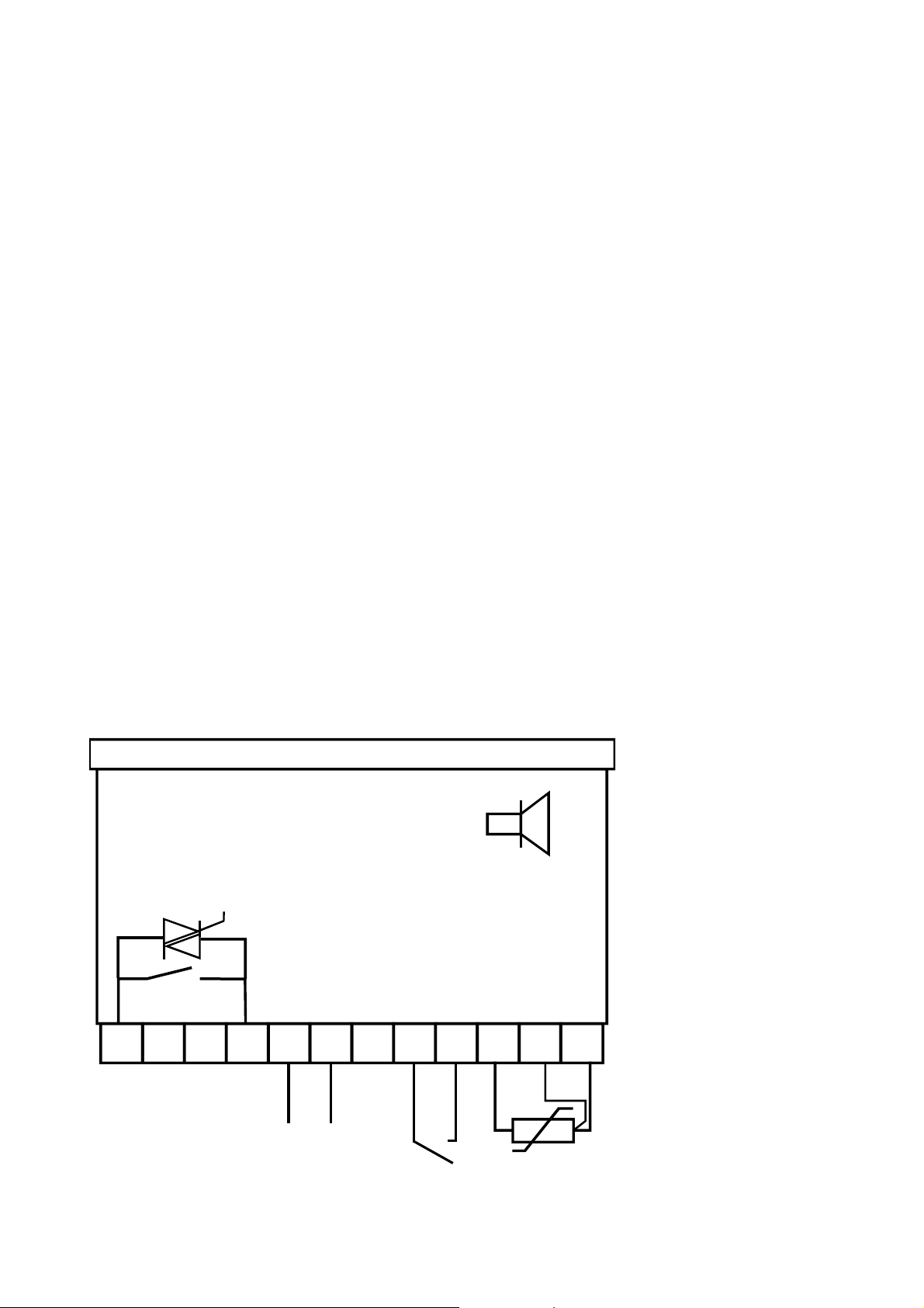
Technical building
The machine of the cooling appliance consists of an hermetic closed compressor refrigeration
system.
The refrigerating machine of the KBT 02-51 is regulated with an two-step-regulator.
The chamber consists of stainless steel 18/10.
Housing of stainless steel. Only front panel is with white RAL 9003 electrostatic coated.
Set in operation
Put the cable in a socket with earthing-contact. Voltage, currency and frequency are shown on the
rating plate.
Switch on the cooling machine, then must light up the green pilot light in the switch.
Attention: Take care that the white lid is on the top of the chamber and closes tightly to avoid new
air with humidity inside the chamber which leads to high icing.
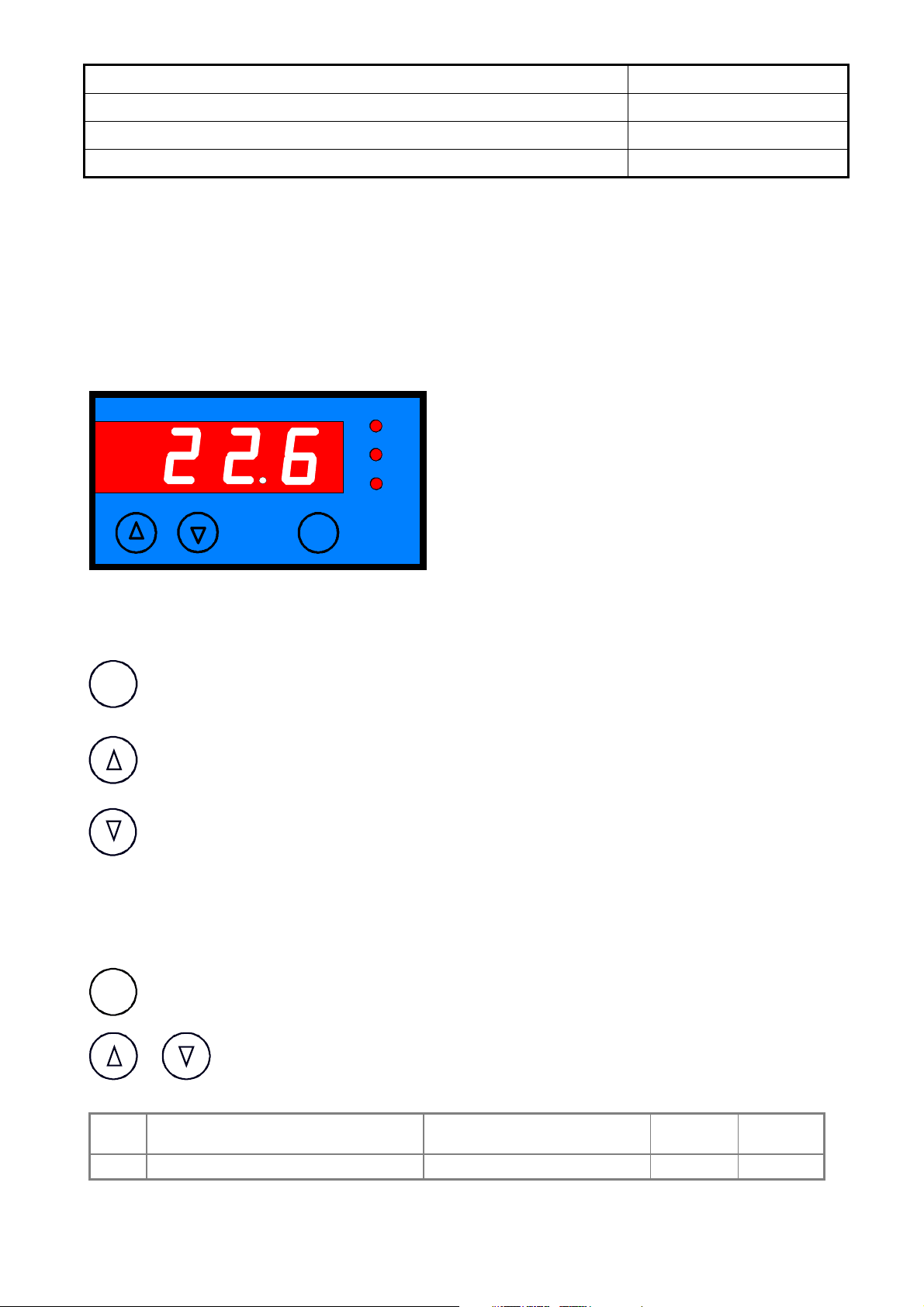
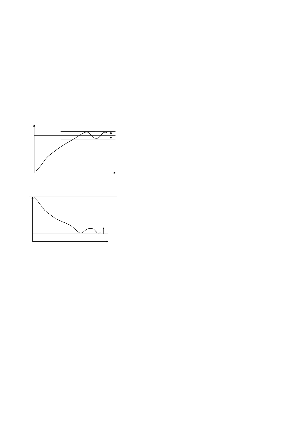
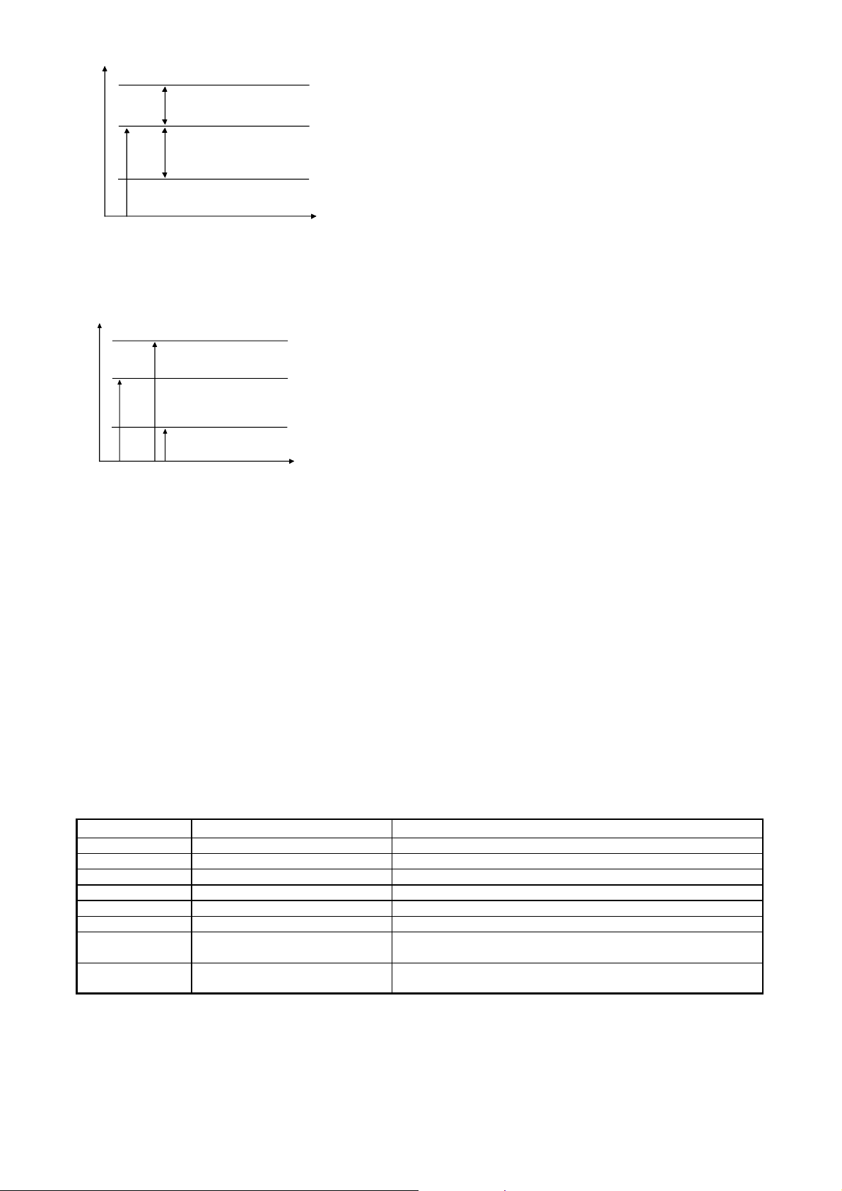
Adjusting the system
Electronic two-point control with digital display, setpoint control (SET key) and PT-100 internal
temperature sensor. Precise to +/1,0K. Control shows actual value when unit switched on. To set
the setpoint, press the SET key and then use the cursor keys to adjust. Once setting is complete,
press SET key briefly to check setpoint.
Temperature range -30 / -50°C.
Security equipment
The compressor is configured with an internal thermo-switch, which switches off at overheating. A
re-connection of the aggregate is only possible when the compressor has cooled down (after 1
hour).
Disturbance
If the equipment works not normally, may be a great temperature difference or an outfall from the
refrigeration, you have to check at first the environmental reference conditions (ambient
temperature, ventilating around the equipment). Then the condenser at the backside have to check
up on pollution and dusty and as a precaution cleaned with compressed air blow through it.
Maintenance and servicing
The hermetical cooling aplliance is convenient for the continous operation and need no
maintenance. The condenser at the backside should be regularly checked and will be cleaned, this
depends on from degree of dusty of the site. Attention! Get notice that this leads to the outfall of the
cooling appliance through overheating.

Refrigeration Diagram Wiring Diagram
M1
V1
W1
Ft
Y1
W1
L
N
N1
L1
L2
M1 V1
S1
x1 x2
123 4 5678910 11 12
K1 Hybrid R1
PT100
230V
50Hz
E1
F1
Refrigerant R 507-x Terminal:
PE N L N1 L1 L2 1 2 PE
Quantity:
120 gr. Voltage: 230 V / 50 Hz Current 1,5 A
Parts List
M 1 Compressor TL5G
V 1 Fan 4715MS
W 1 Condenser FCE 12.1.180
Ft Filter Drier 10-6-2
Y 1 Capillary Tube
S 1 ON/OFF Switch 3.3112.80
R 1 Temperature Controller ST 71-IG1BA.10FPS
F 1 Sensor PT100
12’2010
Parts List
KBT 02-51

ST71
-
IG1BA.10FPS
900212.27
PT100, 230V AC, Hybrid output H1, digital input E1, screw terminal
284836
Stand: 10.07.2001
Temperature controller
General Data
The control unit ST710-IG1BA.10 is specially designed for thermostatic controll applications. The unit works together
with resistance sensors PT100.
The unit offers beyond the temperature regulation a wide range of other functions.
The output can be programmed to different functions (Parameter A1).
SET
°C
K1
E1
Description
SET-key:
The display normally shows the actual value. When the SET button is pressed , the display changes to show
the Control Set point.
UP-key:
With the UP key it is possible to start a manual defrost.
DOWN-key:
With the DOWN key it is possible to cancel the alarm buzzer.
First level (Set point Adjustment)
Display of the Set Values
The display normally shows the actual value of the process temperature. When the SET button is pressed , the display
changes to show the Control Set point (Desired temperature)
Simultaneously press the SET button with either the UP or DOWN button to increase or decrease the Set
point. Please release the UP or DOWN button before releasing the SET button and the new value is loaded
into the non-volatile memory.
Para-
meter
Function Adjustable range Standard
Setting
Customer
Setting
S1 Set point P4...P5 0,0 °C
SET
SET

Second level (P-level)
Setting of control parameters
In order to prevent accidental or unauthorised changes to the pre-set parameter values, access to the P-Level has been
made difficult.
For more details please contact the manufacturer.
Second level, P-Parameters
P2: Hysteresis K1
The hysteresis for contact K1 can be either symmetrical about the Set point, or to one side of the Set point (parameter
A40). If symmetrical hysteresis has been selected, then one half of the total hysteresis is above and half below the Set
point (see Figure 1).
If one side of Set point has been selected, then the total hysteresis is below the Set point in the heating mode and above
the Set point in the cooling mode (see Figure 2).
Please note that small hysteresis values lead to an increased switching frequency and that the lifetime of the output
relays is decreased correspondingly. In critical cases, the controller can be equipped with semiconductor relays.
Setpoint
T
t
symmetrical
hysteresis
Heating or cooling control
Figure 1
T
t
po s. Hysteresis
Setpoin t
Cooling
control
Figure 2
P4: Control range limitation - minimum Set point
P5: Control range limitation - maximum Set point
Upper and lower control range limits can be set for the Set point. This prevents the end user from adjusting the controller
to unattainable or dangerous Set points.
P6: Actual value correction
A + or - calibration adjustment can be made to the Actual Value indication. It is effective over the entire measurement
range.
P19: Keyboard lock
Adjustable Range: 0 = not locked
1 = locked
Standard Setting: 0
The keyboard lock disables the controller keypad and prevents operator adjustment of the Set point.
P30: Lower boundary value for alarm
P31: Upper boundary value for alarm
the alarm values have an adjustable hysteresis (see P32). It can be set to operate as either a boundary or a range
alarm.
Boundary alarm function (see Figure 3)
LED 3 is illuminated and/or contact K3 is closed if the process temperature rises above the upper, or below the lower
boundary values.

T
t
Alarm "on"
Alarm "off"
Alarm "off"
Alarm "on"
Setpoint
upper boundary ( relative )
lower boundary ( relative )
Figure 3
Range alarm function (see Figure 4)
Opposite switching behaviour to the boundary value alarm LED 3 is illuminated and/or K3 is closed if the process
temperature remains between the boundary values.
T
t
Alarm "off"
Alarm "on"
Alarm "on"
Alarm "off"
upper boundary ( absolut )
lower boundary ( absolut )
Setpoint
Figure 4
P32: Hysteresis alarm
The hysteresis for the alarm is always to one side of the Set point .
It is below the Set point in the upper value and above the Set point for the lower value.
d0 Defrost interval
This parameter determines the time interval between the start of successive defrosting periods. The initial start time is
determined by the time of "Mains on".
Defrosting can be initiated by interrupting the defrosting interval in advance by a manual defrost. (Press the "UP-button
for a minimum of 3 seconds)
d2 Defrost temperature
If the actual temperature is above this value defrosting ends.
d3 Defrost time limit
Defrosting ends latest as set here.
Error codes
Display
error
What to do
F1L sensor short circuit new sensor
F1H sensor failure new sensor
F3L Boundary alarm Temperature low
F3H Boundary alarm Temperature high
F4 Alarm at connection E1 Liquid level sensor alarm --- control level of cooling liquid
--- Keyboard lock active see Parameter P19 or A19
display flashing,
buzzer
Temperature alarm
(see A31)
cancel buzzer
with ∇button
EP lost of data
in EE-Prom
repair of controller

TECHNICAL DATA
Measuring Input
F1: Resistance thermometer Pt100
Measuring range: -80...400°C
Measuring accuracy: +/- 1K or +/- 0,5%
of scale range, which ever is greater
Output
K1: Relay, changeover contacts, 12A 250V
Display
One 3-digit, 13 mm high, red LED display
Power Supply
230V, 50Hz / 60Hz, current consumption max. 20mA
Installation Data
Front panel: 84 x 42 mm
Panel cut out: 68 x 32 mm
Depth: approx. 85 mm incl. terminals
Mounting: fixing strap
Enclosure
Front IP65
Weight
approx. 200g
Ambient Conditions
Storage temperature: -20...+70 °C
Operating temperature: 0...+55 °C
Relative Humidity: max. 75% without dew
Hybrid
250V~ 16A
F1
Pt100
1 2 3 4 5 6 7 8 9 10 11 12
E1
230 V
50/60Hz
Summer
Wiring diagram ~
Table of contents
Other Fryka Freezer manuals
Popular Freezer manuals by other brands

PARRY
PARRY CHEST FREEZER instruction manual

Polar Refrigeration
Polar Refrigeration DN492-A instruction manual

montpellier
montpellier MIFF730FF Installation and operating instructions

Continental Refrigerator
Continental Refrigerator 1F-LT-GD Specifications

OZtrail
OZtrail ELE-FF045S-G owner's manual

GE
GE FUF1 Owner's manual and installation instructions