Frymaster UHC-P User manual

Frymaster, a member of the Commercial Food Equipment Service Association, recommends
using CFESA Certified Technicians.
*8196044* 24-Hour Service Hotline
1-800-551-8633
Price: $6.00
819-6044
FEB 13
UHC-P /HCP
Service, Parts Manual for 4, 2-Slot and Narrow Models

NOTICE
IF, DURING THE WARRANTY PERIOD, THE CUSTOMER USES A PART FOR THIS ENODIS
EQUIPMENT OTHER THAN AN UNMODIFIED NEW OR RECYCLED PART PURCHASED DIRECTLY
FROM FRYMASTER DEAN, OR ANY OF ITS AUTHORIZED SERVICE CENTERS, AND/OR THE
PART BEING USED IS MODIFIED FROM ITS ORIGINAL CONFIGURATION, THIS WARRANTY WILL
BE VOID. FURTHER, FRYMASTER DEAN AND ITS AFFILIATES WILL NOT BE LIABLE FOR ANY
CLAIMS, DAMAGES OR EXPENSES INCURRED BY THE CUSTOMER WHICH ARISE DIRECTLY
OR INDIRECTLY, IN WHOLE OR IN PART, DUE TO THE INSTALLATION OF ANY MODIFIED PART
AND/OR PART RECEIVED FROM AN UNAUTHORIZED SERVICE CENTER.
THE CABINET IS NOT SUITABLE FOR OUTDOOR USE. WHEN OPERATING THIS UNIT, IT
MUST BE PLACED ON A HORIZONTAL SURFACE.
THE CABINET IS NOT SUITABLE FOR INSTALLATION IN AN AREA WHERE A WATER JET
CAN BE USED. THIS APPLIANCE MUST NOT BE CLEANED WITH A WATER JET.
FOR YOUR SAFETY
DO NOT STORE OR USE GASOLINE OR OTHER FLAMMABLE VAPORS AND LIQUIDS IN
THE VICINITY OF THIS OR ANY OTHER APPLIANCE.
DO NOT OPERATE OR SERVICE THE CABINET WITHOUT FIRST READING THIS MANUAL.
DO NOT OPERATE THE CABINET UNLESS IT HAS BEEN PROPERLY INSTALLED AND
CHECKED.
DO NOT OPERATE THE CABINET UNLESS ALL SERVICE AND ACCESS PANELS ARE IN
PLACE AND PROPERLY SECURED.
DO NOT ATTEMPT TO REPAIR OR REPLACE ANY COMPONENT OF THE CABINET UNLESS
ALL POWER TO THE UNIT HAS BEEN DISCONNECTED.
USE CAUTION WHEN SETTING UP, OPERATING, OR CLEANING THE CABINET TO AVOID
CONTACT WITH HEATED SURFACES.

Table of Contents
Theory of Operation 1-1
Service Procedures 2-1
Re-addressing Cabinet 3-1
Troubleshooting 4-1
Illustrated Parts List 5-1
Wiring Diagrams 6-1

Cabinet Service Procedures
1-1
1 Functional Description
1.2 Theory of Operation
The CABINET operates on 208-250VAC 50 or 60 cycle single-phase power. The main switch
activates a relay, which supplies line voltage to two distribution boards, two cooling fans and a 12-
volt transformer, which supplies a power supply. The power supply provides 5VDC to the
communication board and the distribution boards.
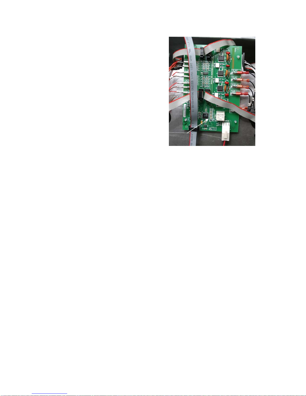
A ribbon cable connects the communication board to both distribution boards, connecting at J9.
Ribbon cables, which carry 5V DC, also connect the distribution boards to the displays. The
resistance of RTDs attached to the heater plates is monitored by the distribution boards. The board
switches power through solid-state relays to the heater plates when the resistance, which is used as
an indicator of temperature, falls out of the range for the product held in the cabinet.
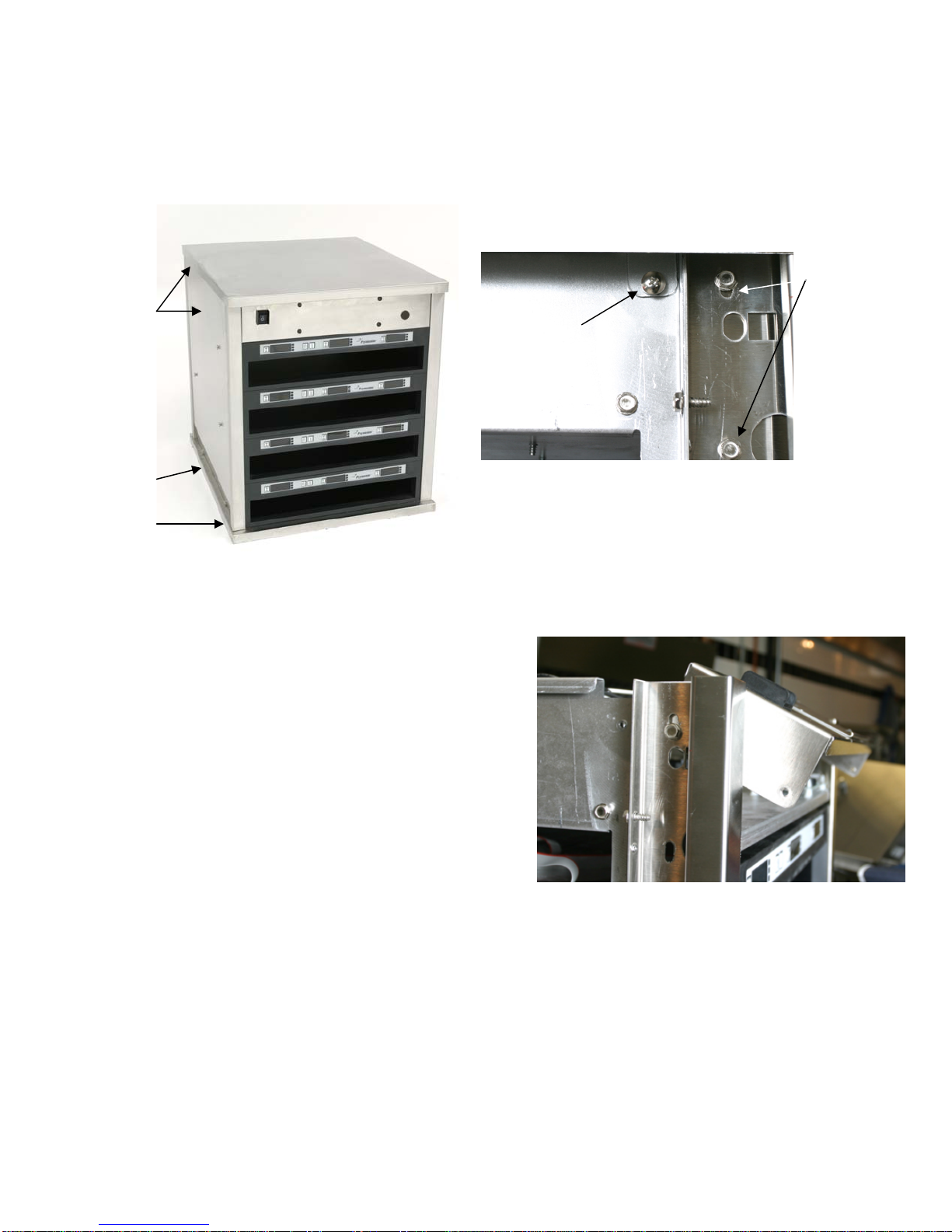
The switch, transformer, communication board, cooling fans and power supply are mounted under
the top of the unit. There is a small dark lens portal on the upper right side of the cabinet, which
allows infrared communication between the cabinet and a Palm Pilot. The distribution boards are
mounted on the left side (as viewed from the front).
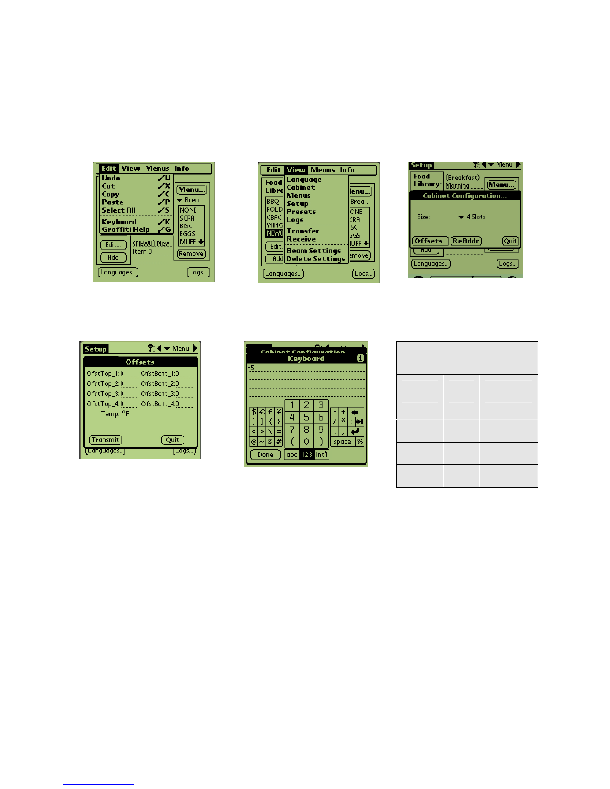
The parameters for holding temperatures are transferred to the cabinet’s communication board via a
Palm Pilot with special CABINET software. All programming of the cabinet is done on the Palm.
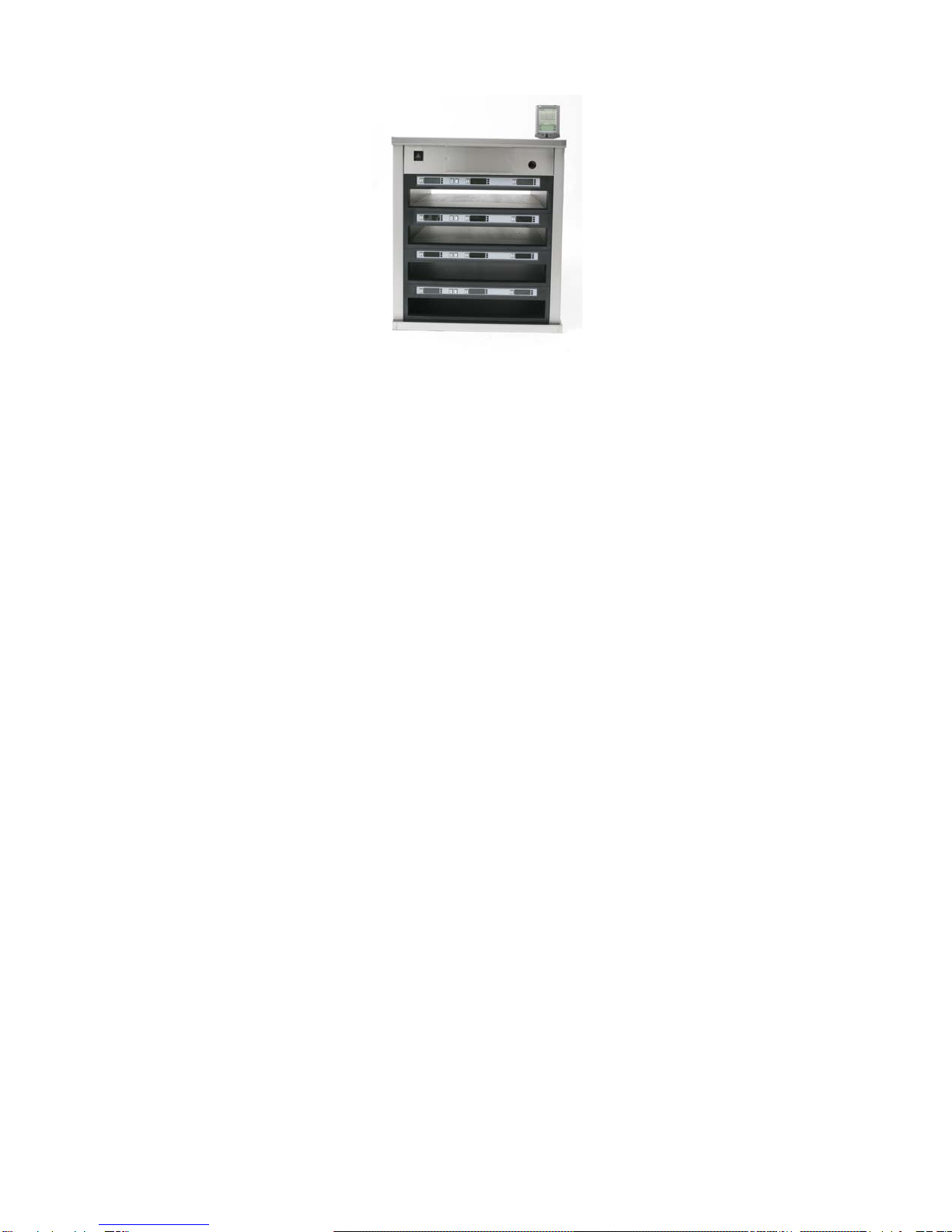
Figure 1: UHC-P cabinet
IR port
Timer key
Menu key
Temperature
Key
LEDs
Power switch
Timer keys
Note: The illustrations
for these service
procedures are of the 4-
slot full size UHC-P. The
procedures are similar
for the 2-slot and the
narrow models.
NOTE: This manual covers the UHC-P, the original
PDA-programmed cabinet for McDonald’s and the HCP
or Holdmaster, a similar cabinet made for the general
market. UHC-P parts are compatible with the HCP,
except for the heater plates and bezel.

Cabinet Service Procedures
1-2
1.3 Start Up Indicators and Test Points
Upon startup, the communication board beeps. On the
distribution boards, an LED flashes rapidly for a few
seconds and then slows to one flash every two seconds.
The displays will show the version number of the
cabinet’s firmware and then the slot’s status.
LED

Cabinet Service Procedures
2-1
2 Service Procedures
DANGER: Failure to disconnect the power supply before servicing could result in serious
injury or death. The cabinet power switch DOES NOT disconnect all incoming power to the
cabinet.
2.1 Accessing the Electronic Components
1. The component shelf is accessed by removing two
screws on each side of the unit. See figure 1.
2. Lift and remove the sides, which exposes screws
that hold the top in place. See figure 2.
3. The front panel, which holds the switch and the IR
lens, can be rotated forward by removing a screw on
either side and loosening two others. See figure 3.
With the removal of four more screws, the
component shelf will slid forward if necessary.
Figure 1: The side panels must be removed to
access the component shelf.
The side panels are
secured with two
screws at the base.
Figure 2: Four sheet metal tabs hold the top in place.
Remove these screws at each corner and lift off the
top.
Tab and screw
securing top
Remove the
bottom screw
and loosen
the top one to
tilt out the
front panel.
Figure 3: Remove the screws which secure the
component shelf, allowing the shelf to be pulled
forward.
The top is held
in place by
screws behind
the side panel.

Cabinet Service Procedures
2-2
Under the top
Figure 4
Com board
Rela
y
Transformer
Power
supply
Fuses
Fans

Cabinet Service Procedures
2-3
All the components are readily removed. There are no replaceable components on the circuit boards.
The replacement of a display, distribution or communication board will require re-addressing the
cabinet, covered in Section 3.
2.2 Tests
2.2.1 Transformer
1. Disconnect power to cabinet. Remove side and top panels, unless stacked. See the service
procedures for access instructions, Section 2.1
2. Check for 208VAC at the primary, 12VAC at the secondary terminals.
2.2.2 Power Supply
1. Disconnect power and check all terminals and
connections for loose or disconnected wires.
2. Apply power and check for +5VDC at the J5 terminal
on the communications board, using the center pin for
the positive lead and either adjacent for the negative
lead.
2.2.3 RTD
1. Remove the leads from the suspect RTD and test for
resistance. selected temperatures and resistances are
show in Figure 7, a chart at right.
NOTE: After testing, reconnect all leads to their
original positions.
Sensor
(°F) Resistance Sensor
(°C)
60 106.065 15.55
70 108.224 21.11
80 110.380 26.66
90 112.532 32.22
100 114.680 37.77
110 116.825 43.33
120 118.966 48.88
130 121.104 54.44
140 123.239 60.00
150 125.369 65.55
160 127.496 71.11
170 129.620 76.66
180 131.740 82.22
190 133.856 87.77
200 135.969 93.33
210 138.078 98.88
220 140.184 104.44
230 142.286 110.00
240 144.385 115.55
250 146.480 121.11
260 148.570 126.66
Figure 7: RTD resistance chart

Cabinet Service Procedures
2-4
2.2.4 Distribution Boards
1. Check for line voltage
between the heater
plate terminal on the
board and the terminal
block for the suspect
heater. Note: Line
voltage is only seen
when the slot is calling
for heat.
2. Check for line voltage
between the power
input terminal and the
terminal block.
3. Check for +5VDC at
the Power In terminal
between the positive
center pin and either
adjacent pin.
NOTE: After testing,
reconnect all
connections to their
original positions.
2.2.5 Display
1. Connect the ribbon cable from a faulty display to the connector of a properly working display to
isolate the problem to the display or the distribution board.
2.2.6 Shorted Triac
1. Turn the suspect slot off and measure voltage between the suspect heater lead on the distribution
board and the terminal block With the slot off, there should be no line voltage. If the triac is
shorted, you will measure AC line voltage. If the triac is half waving, you will get DC voltage of
approximately one-half the line AC voltage.
2.2.7 Calibration
Calibrate the top and bottom plates in all four UHC slots by performing the following procedure
with the slots clean, empty and at operating temperature for at least 30 minutes.
1. Press the temperature key to ensure the slot is at setpoint.
2. Slide the Atkins sensor into a slot with the sensor facing up to measure the top heater plate or
down to measure the bottom heater plate. Move the sensor to the center of the plate. To get an
accurate reading, the sensor must be within ±1 inch (25mm) of the center of the plate.
Figure 8: Testing distribution board.
Line voltage between
slot leads and
common on terminal
block with slot calling
for heat.
Line Voltage between
power input and
common on terminal
block.
+ 5VDC between
positive center pin
and either
adjacent pin.

Cabinet Service Procedures
2-5
3. Allow three minutes for the sensor to stabilize.
4. Read the temperature on the Atkins meter and compare to the reading from the cabinet, which is
displayed by pressing the temperature key once for the top plate temperature and twice for the
bottom plate. The displayed temperature should be within ±5°F (±3°C) of the meter. If the
reading is out of tolerance, perform the following procedure.
Launch the UHC-P software on the Palm and follow these steps:
Step 1: Tap the left corner
of the display in Setup or
Menu mode. A menu bar is
dis
p
la
y
ed.
Figure 2: Tap View in the
menu bar and tap Cabinet
in the pull-down menu.
Step 3: The Cabinet
Configuration menu is
displayed. Tap the
Offsets button in the left
corner.
Step 4: The Cabinet
Configuration Offset menu
is displayed. The offset
entry fields for the slots are
arranged left to right and
top to bottom
Step 5: Tap on the number
line by the plate being offset
and then the number in the
bottom right of the Palm
display. Use the backspace
key to erase number in the
field and use the keypad to
enter the desired offset.
See examples in Table 1 (at
right). Tap Done.
Offset Entry
Examples
Display Meter Correction
150°F 155°F 5
150°F 145°F -5
66°C 69°C 3
66°C 63°C -3
Table 1

Cabinet Service Procedures
2-6
2.2.7 Heater Plate
1. Disconnect power to the cabinet. On stand-alone units, remove side and top panels. On stacked
units, see Service Procedures for instructions on accessing the top panel.
2. Disconnect the black heater lead and the two RTD leads (brown and red) of the suspect plate
from distribution board. Measure resistance of the heater from the black lead to any terminal on
the white terminal block. Resistance should be 140-150 ohms.
3. Measure resistance across the brown and red RTD leads. Resistance must be within a range of
104-148 ohms. Resistance at room temperature is approximately 107 ohms. See chart on Page
2-3 for resistance at different temperatures. If either resistance is incorrect, replace the heater
plate.
2.2.8 Display Meanings
1. SLOT TEMP HIGH OR SLOT TEMP LOW and no audible alarm. This is normal when
the slot is changing temperature in association with a menu change.
2. LLLL means the RTD indicates a temperature below 50°F (10°C). Unit will automatically heat
at 20 percent until temperature is above 50°F (10°C), then operate normally.
3. HHHH means RTD indicates the temperature is above 255°F (124°C), but below "Open" circuit
resistance, which causes SENS ALARM.
UHC VERSION _ _ _ (version number will vary) appears for five seconds when the
unit is turned on.
Step 6: The entered offset is
visible on the menu. In this
case we offset the top slot’s
top heater plate –5°F. Adjust
other slots as necessary.
Step 7: With the Palm horizontal and
approximately one foot from the
receiving lens on the cabinet, tap the
Transmit button. The Transfer menu will
be displayed. A message will be
displayed when the transfer starts and
when the transfer is complete.

Cabinet Service Procedures
2-7
2.3 Removing/Replacing Components
1. The bezel
holding
the
controller
display is
secured
in the
cabinet
by two
allen and two hex-head screws. The bezel is shown removed (Figure 9). Four screws secure the
display in the bezel. The ribbon cable attaches to the distribution board on the side of the unit.
2. A baffle
(Figure 10) is
behind the
display and it
must be
removed to
feed the
ribbon cable
from a new display through the cabinet framework to the distribution board.
3. After replacing a display, the cabinet must be re-addressed. See Section 3.
2.3. 1 Removing/Replacing a Distribution Board or Communication Board
1. Remove and mark the wires on the faulty component.
2. Remove the board by lifting it from its standoffs.
3. Rewire the board.
4. After replacement of a communication, display or distribution board, the cabinet must be re-
addressed, which is covered in Section 3.
2.3.2 Removing a Slot
Figure 11: A faulty slot is slipped from the cabinet.
Figure 9: The bezel holding the display is shown removed.
Figure 10: A baffle is secured behind the bezel.

Cabinet Service Procedures
2-8
1. Perform steps in Section 2-1. Disconnect the faulty slot from the distribution board, and terminal
block.
2. Loosen, but do not remove, the screws from each corner of the slot to be removed.
3. Remove wire wraps from wiring harness holding heater and control wires for affected slot.
4. Lifting slightly, carefully slide the malfunctioning slot out of the cabinet. Do not allow the slot to
contact or damage the controls of the unit
below (Fig 11).
2.3.3 Replace Heater Plate/RTD
1. Perform Sections 2-1, 2.3.2
2. Run your fingers around the outside surface of
the slot assembly. There are four raised areas.
These are the setscrews, which hold the heater
plate to the spacer. Punch 4 holes in the
insulation, directly above the location of the
setscrews (Fig. 12).
3. Use an allen wrench to loosen the four
spacer-setscrews along the edges of the plate
(Fig. 12).
4. Slide the malfunctioning plate out of the
spacer (Fig. 13).
5. Slide the replacement plate into position.
Make sure the plate is inserted squarely.
CAUTION
Ensure the heater plate setscrews are tightened securely to the spacer.
Tightening the setscrews will ensure the plate is properly grounded.
Figure 12: Find the set screws under the foil
insulation and push through with an allen wrench.
Figure 13: The heater plate slides from the
insulation.

Cabinet Service Procedures
3-1
3.1 Re-addressing the Cabinet
If any board or display is changed on the CABINET, the unit must be re-addressed. This essentially
tells each board which position it occupies. The cabinet must also be re-programmed with the Palm.
Changing the power supply doesn’t require re-addressing or programming. (Note: Re-addressing a
Narrow unit is slightly different and a separate button-push sequence is provided below.)
The process of re-addressing begins with the Palm. The security level has to be changed to admin in
the Palm software to access the re-address feature. The cabinet must be ON. Follow these steps to re-
address the cabinet with the Palm.
ix
Step 5: The Cabinet
Configuration screen is
displayed. Make sure that
the proper slot size is
displayed ( 2 slots, 4 slots,
narrow). (NOTE: The button-
push sequence for the
Narrow unit is different and
covered in Steps 7N-14N on
the adjoining page.) With
the Palm horizontal and near
the lens on the UHC-P
cabinet, tap the ReAddr
button in the bottom center
of the screen.
Step 6: The addresses of
the cabinet's boards will be
beamed to the cabinet. A
success message will
display when the process is
complete. Press 1 Button
will be displayed on each
slot.
Button-Push Sequence for 4, 2-slot Units
Step 7: Press and release the right timer key
on the top slot on front of the unit.
Step 8: Repeat for second, third and fourth
(if present) slots.
Step 9: Move to the back of the unit and
press the left top slot timer key.
Step 10: Repeat for second, third and fourth
slots.
Step 11: *Press the back bottom left timer
button a second time within 30 seconds of
the previous button push.
Step 12: Press temperature key on top front
slot. Verify temperature display and repeat
steps for remaining slots.
Step 13: Repeat step 12 on back displays if
present.
Step 14: Repeat readdress sequence if
temperature displays fail.
Step 4: Tap the Setup bar in
the top left to reveal the menu
bar. Tap View and in the drop-
down menu highlight Cabinet
by tapping it.
Step 1: Tap the key icon
at the top of the screen
(see arrow) to access the
security manager.
Step 2: Use the
Palm's keyboard
feature (see arrow)
to type admin in the
security manager
dialog box. Tap OK.
Step 3: A dialog box
appears, saying the
security level has been
changed. Tap OK.
*NOTE: Failure to
press the button in
less than 30 seconds
will cause the cabinet
to react slowly to
button pushes.
Repeat readdress
sequence to eliminate
delay.
NOTE:Thecursor
mustbeintheblank
lineofthedialogbox
toaccessthe
keyboard.

Cabinet Service Procedures
3-2
Step 15: Beam over the cabinet
configurations with a Palm,
which holds the restaurant’s
desired cabinet configurations
by opening the UHC-P software
to the setup window.
Step 16: Ensure the dark receiving
lens on the front of the cabinet is
clean. Hold the Palm Pilot parallel
with the floor and aim it at the lens
from no more than one foot away.
Tap the Transfer button.
Tap the TxirDa button.
The cabinet will beep and the Palm
Pilot will display a message,
indicating a successful transfer.
*All five menus established on the
Palm are now accessible with the
menu key on the cabinet. Note:
Text on buttons can vary between
software versions.
Button-Push Sequence for
Narrow Unit
Step 7N: Press and release
the top front timer key.
Step 8N: Repeat for second,
third and fourth slots.
Step 9N: Move to the back of
the unit and press the top
temperature key.
Step 10N: Repeat for second,
third and fourth slots.
Step 11N: *Press the back
bottom timer key within 30
seconds of the previous
temperature key push.
Step 12N: Press temperature
key on top front slot. Verify
temperature display and repeat
steps for remaining slots.
Step 13N: Repeat step 12 on
back displays if present.
Step 14N: Repeat readdress
sequence if temperature
displays fail.
*NOTE: Failure to press the button in
less than 30 seconds will cause the
cabinet to react slowly to button pushes.
Repeat readdress sequence to eliminate
delay.
NOTE: It is not necessary to
beam menus separately. All
menus in the Palm — the
displayed menu and all
others — are moved to the
cabinet with each transfer.

Cabinet Troubleshooting
4-1
Symptom Possible Causes Tests
Unit fails to
power up; fans
don’t run.
•No power to cord.
•Blown 20 amp fuse.
•Check for line voltage at the
switch and the transformer.
Unit powers up
and fans run; a
display fails to
light.
•Broken or improperly
seated ribbon cable.
•Defective display.
•Switch ribbon cable from
functioning display to failed
component to isolate problem.
Unit powers up
and fans run; all
displays fail to
light.
•Failed transformer.
•Failed power supply.
•Check for 12VAC at
transformer.
•Check for 5VDC at
communication board and
distribution boards.
Slots heat
improperly or
not at all.
•Improper wiring on
distribution board.
•Defective distribution
board.
•Defective heater.
•Defective sensor.
•Ensure heater leads and power
inputs on the distribution boards
are properly seated.
•Test for 208VAC input on
distribution board and 208VAC
output from heater leads to
heater plate when the unit is
calling for heat.
•Switch power leads from
properly operating slot to faulty
slot to isolate problem.
•Check resistance of RTD lead
against temperature chart. See
Page 2-3.
•Switch RTD lead from properly
operating slot to faulty slot to
isolate problem.
•Test continuity of heater plate.
Cabinet beeps
continuously.
•Stuck display button.
•Defective display.
•Shorted capacitor on
one or more display.
•Bad communication
board.
•With power applied, unplug
each display, one at a time, to
isolate beeping. Replace
beeping display.
•Beeping continues? Replace
communications board.

Cabinet Troubleshooting
4-2
Unit locks up;
buttons won’t
respond.
•Cabinet not
readdressed. •Readdress cabinet.
Display shows
Off or Clean
Mode only.
•Cabinet not
reprogrammed
after
readdressing.
•Reprogram cabinet.
After brief
operation, all
displays dim
except
countdown.
•Failed
transformer. •Check for 12VAC at
transformer.

Cabinet Parts
5-1
NOTE: This manual covers the UHC-P, the original PDA-programmed cabinet for McDonald’s and the HCP or
Holdmaster, a similar cabinet made for the general market. UHC-P parts are compatible with the HCP, except for the
heater plates and bezel.
5 Parts Lists, Exploded Views
5.1 Cabinet Components
Item 4- Slot Part # 2-Slot Narrow Description
1 210-3659 210-3710 210-3659 Left Side Cabinet
2 826-2644 826-2644 826-2644 Distribution board
3 806-7904SP 806-7904SP 106-4549 Base
4 106-4571 106-4571 N/A Bracket Assembly, UHCII Insulator
5 106-4225 106-4225 106-4547
Rear Fascia Assembly without Menu.
6 Component shelf, See page 5-2
* 809-0256 809-0256 809-0256 Button Hanger Nut
7 806-7906SP 806-7906SP 106-4544SP Top Cap Assembly
8 807-4036 807-4036 807-4036 ON/OFF Switch
9 816-0634 816-0634 816-0634 Communications port cover
10 809-0581 809-0581 809-0581 Nut, ½ N.P.T. Locking
11 809-0582 809-0582 809-0582 Washer, ½ N.P.T. Star-Lock
12 200-3639 200-3639 200-3639 UHC Cordset Bracket
13 807-2473 807-2473 807-2473 Pin & Sleeve Cordset with Strain Relief 8073238 and washer.
* 807-2474 807-2474 807-2474
Cordset, Twist Lock Power Cord (HC-P)
* 807-4409 807-4409 807-4409 UHC-P Cordset, includes strain relief (China)
14 910-4876 910-9452 910-4876 Right Side Cabinet Assembly
15 Slot assemblies, see page 5-3
* 807-2766 807-2766 807-2766 Power Line Filter, CE only
* 826-2632 826-2632 826-2632 Palm Tungsten with UHC-P software

Cabinet Parts
5-2
Item 4- Slot Part # 2-Slot Narrow Description
* 826-2633 826-2633 826-2633 Palm Tungsten with UHC-P software and Int’l power adapters
* 108-0902 108-0902 108-0902 Palm Tungsten with HCP software
* 826-2635 826-2635 826-2635 Palm Tungsten with HCP software and Int’l power adapters
5.2 UHC-P/HCP Component Shelf
1
2
3
4
5
67
8
9
Item 4-slot Part # 2-Slot Narrow Description
1 826-2590 826-2590 826-2590 Board, UHC-P/HCP Communications Board
2 807-3490 807-3490 807-3490 Relay, Omron Power
3 807-4024 807-4024 807-4024 Transformer, 208-240/12V 60VA
4 807-2820 807-2820 807-2820 Block, Fuse Omni-Blok
5 807-2819 807-2819 807-2819 Fuse, 3AB-314 20 amp
6 812-1306 812-1306 812-1306 Metal Oxide Varistor
7 807-2665 807-2665 807-2665 Blower, Exhaust
8 106-9516 106-9516 106-9516 Power Supply
9 810-1164 810-1164 810-1164 Block, I Plc Screwless Terminal
* 807-3918 807-4071 807-3918 Ribbon Cable, Communications for UCH-P/HCP
*Not Illustrated

Cabinet Parts
5-3
5.3 Slot Assembly
Item Part Number Description
1 816-0584 Bezel
* 816-0714 Bezel, HCP
2 812-1814 Heater plate
* 106-6577 Heater plate, HCP
3 810-1286
Spacer, extruded
4 826-2588 Display
5 816-0572 Bezel, Spod
6 816-0649 Bezel, narrow
7 810-1286 Spacer, extruded
8 807-4065 Heater plate, narrow
9 807-4681 Display, narrow
* 803-0370
Wire Rack for 816-0726 (HCP Non-McDonald’s Only)
* 816-0727
High-side tray, (HCP Non-McDonald’s Only)
* 816-0726
Low-side tray, (HCP Non-McDonald’s Only)
Other manuals for UHC-P
2
This manual suits for next models
1
Table of contents