Furniture of America YNJ-1416-1 User manual

Page 1 of 13
The Assembly Rating is a 5-point system that
show the degree of effort needed in assem-
bling a specific product (with 1 being easy and
5 being difficult). For most products, two per-
sons are recommended.
Allen Wrench
Phillips Screwdriver (Included)
(Not Included)
YNJ-1416-1 & 1416-5 & 1416-6
ASSEMBLY INSTRUCTIONS
ASSEMBLY RATING TOOLS REQUIRED FOR ASSEMBLY
14-10-10
EASY DIFFICULT 2 PERSONS RECOMMENDED

Page 1 of 15
Thank you for your purchase!
We hope you will enjoy your new product for many years to come. Our commitment
to providing quality products does not simply end when a purchase is made. We
stand behind our products and will provide any support needed in order for you to
fully enjoy your purchase. Your satisfaction is the greatest recognition we could
have.
Because we value your trust in our company, we will do our best to meet your
service expectations. Should you have any assembly related questions, parts
replacement requests, comments or suggestions, please feel free to contact us any
time. To help expedite the service, please have the assembly instructions available,
along with your order receipt.
www.foagroup.com
Toll-Free 1-888-980-5122 or 1-626-363-9311
1-626-270-4451
Monday to Friday 8:30 a.m. to 5:30 p.m. (PST)
https://twitter.com/foagroup
http://www.pinterest.com/foagroup/
http://instagram.com/foagroup#
https://www.youtube.com/user/FurnitureOfAmerica
Page 2 of 13

Page 3 of 13

Unless you are particularly adept at assembling flat-pack/knock-down
furniture, we understand building ready-to-assemble furniture can be a
frustrating experience for some. To help avoid confusion and to make
the assembly process quicker and smoother, we have provided some
helpful tips. Before you begin the assembly, please read the following:
1. Due to the size and/or weight on most of the ready-to-assemble furniture, it is
highly recommended that the assembly should be done near the area of its
intended location. Make sure you have enough space to move around during
the assembly. ALWAYS have at least two people to help with transporting and
assembling of the product to avoid any potential injury and/or damage.
2. To protect from damage, assemble the item on a clean, protective surface,
such as on a carpet or cardboard.
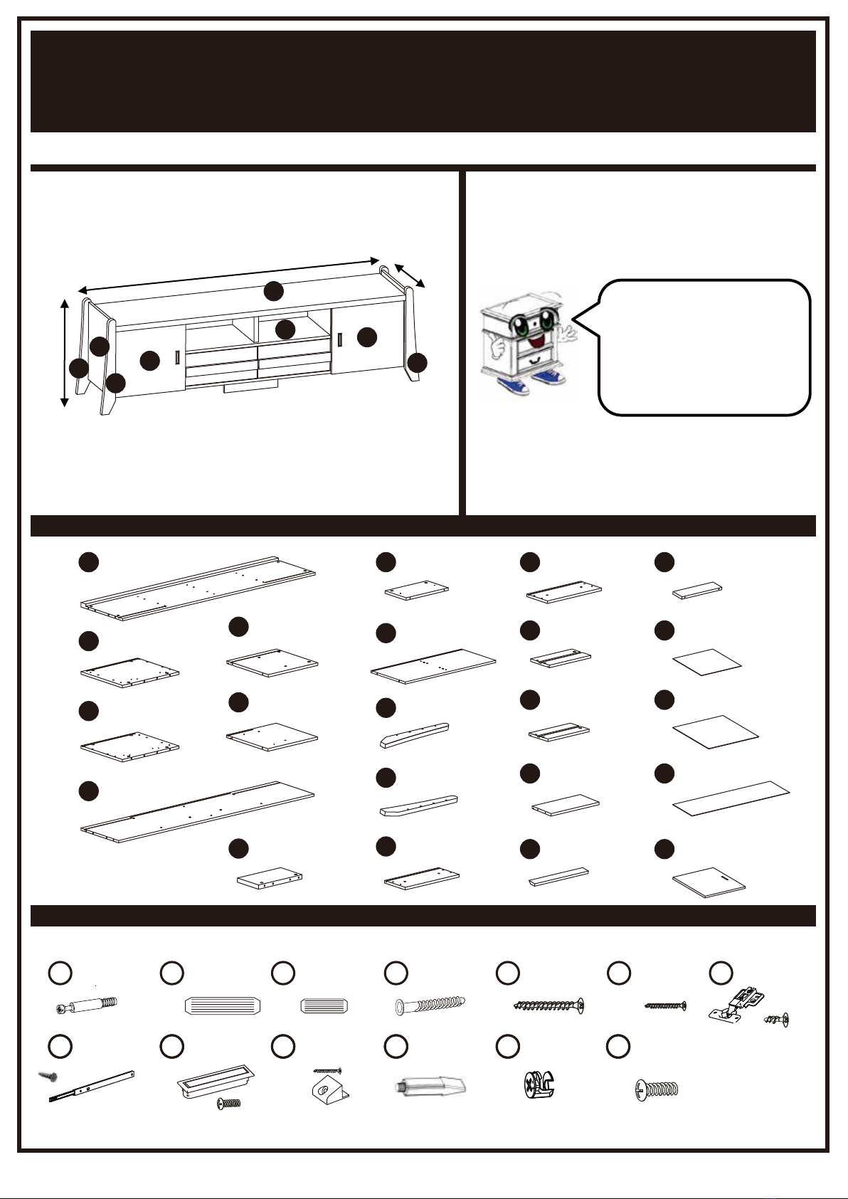
3. Make sure you have taken all the parts and hardware out of their packaging.
Do not throw away packaging material until assembly is completed.
4. Make sure all parts and hardware are accounted for by comparing the actual
parts and hardware to the list provided in the assembly instructions. Also
check for any irregularity such as crack, flaw or improperly drilled hole. If there
is any problem or missing piece, please contact the manufacturer or the
supplier. Please have the model number, part number and a brief description
of the problem ready will help expedite the replacement process.
5. Read the entire instruction manual and view the diagrams first before
assembling. Arrange your parts in order of use and group the identical
hardware together to make it easier to grab each piece as you begin to
assemble.
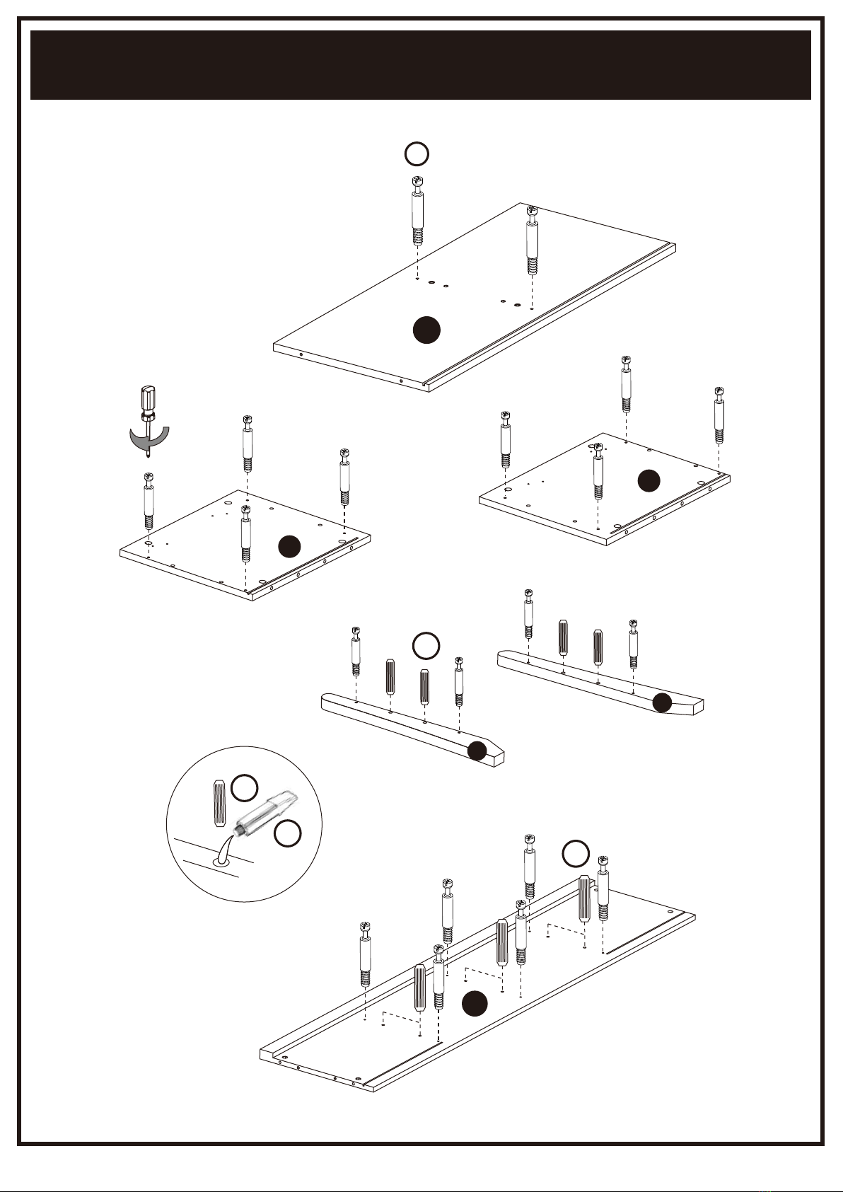
6. During the assembly process, make sure all parts are properly aligned before
tightening with the tool provided or required for the assembly. Do not use
power tools and do not over tighten.
7. When applying glue to the wood dowels to bond the parts together, please be
ABSOLUTELY certain that the parts are correct and lined up with each other
(refer to diagrams and take notice of the various pre-drilled hole locations).
When in doubt, assemble the parts together first and if the parts fit right, then
apply glue to the wood dowels.
PRE-ASSEMBLY INTRODUCTION
Page 4 of 13

CAM LOCK FASTENER ASSEMBLY INSTRUCTIONS
ly
Page 5 of 13

MILTI-FUNCTION CABINET
ASSEMBLY INSTRUCTIONS
Please keep for future reference
MODEL # YNJ-1416-1,1416-5,1416-6
PARTS LIST
HARDWARE LIST
PARTS LIST
Before you begin, please
read “Assembly and
Care Advice”, “Pre-
Assembly Introduction”
and “Cam Lock Fastener
Assembly Instructions”.
Page 6 of 13
DIMENSIONS
70.08”(W) X 15.75”(D) X 20.47”(H)
A1PC
I
V
V
70.08''
20.47''
15.75''
A
B
K
J
K
B1PC
A
C1PC
D1PC
E1PC
F1PC
G1PC
H1PC
I1PC
J2PCS
K2PCS
L1PC
M1PC1PC
N2PCS
O2PCS
P2PCS
Q2PCS
R1PC
S2PCS
T2PCS
U1PC
V2PCS
128PCS 228PCS 34PCS 414PCS 58PCS 64PCS
12S E T 12S E TS S S
18S E T 11PC 128 PCS
16P CS
1 1 1 1 18 9 10 11 12 1 4 PCS
113
74 SETS
8PCS
4PCS
2PCS

ASSEMBLY INSTRUCTIONS
Page 7 of 13
Assembling Drawer’s Runners (a.k.a. Rails, Glides, Slides or Guides)
An assembly of ONE drawer requires two sets of runners. The runner is composed of
an inner rail and outer slide. Please read completely first before assembling.
Mounting the Inner Rail (Fixed) of the Runner: Before mounting, please determine
which side of the panel is the front and rear. The single screw hole on the outer slide
MUST be positioned on the FRONT of the panel. Place the inner rail of the runner in
its correct position and flat on its back. Slide the outer slide out to the way to align the
center or second holes on both ends of the inner rail with the pre-drilled holes on the
panel. For most applications, the center or second holes are used but if not, just make
sure the appropriate rail holes are aligned up with the panel holes. Use two screws to
secure the inner rail of the runner onto the panel.
Mounting the Outer Slide (Moveable) of the Runner: Each outer rail is secured with
a single screw onto the FRONT SIDE of the drawer. Extend the two outer slidesof the
runners and place the drawer in between those two outer slides. Align the pre-drilled
holes on each side of the drawer with the screw holes of the outer slides. Use two
screws to secure from the inside of the drawer into the screw holes of the outer slides.
STEP1
Hardware #8 = 2 runners + 4 screws
2nd Hole
8
E
F
Front
Screw Hole
Screw Hole
Front

ASSEMBLY INSTRUCTIONS
Page 8 of 13
STEP2
Hardware #1 = 24pcs
Hardware #2 = 14pcs
2
2
2
11
A
I
B
1
C
K
J
X2
X2

ASSEMBLY INSTRUCTIONS
Page 9 of 13
STEP3
Hardware #2 = 2pcs
Hardware #8 = 2 runners + 4 screws
STEP4
Hardware #4 = 8pcs
3rd hole
2nd hole
Flip Over
H
H
RD
E
F
I
G
8
2
4
Screw Hole
Screw Hole
Front
Front

ASSEMBLY INSTRUCTIONS
Page 10 of 13
STEP5
Hardware #2 = 8pcs
Hardware #4 = 6pcs
Hardware #12 = 8pcs
STEP6
Hardware #12 = 16pcs
2
11
A
H
D
U
2
4
T
B
C
12
1
12
J
K
BC
and
1
12
12
X2

ASSEMBLY INSTRUCTIONS
Page 11 of 13
STEP7
Hardware #1 = 4pcs
Hardware #2 = 4pcs
Hardware #3 = 4pcs
Hardware #5 = 8pcs
Hardware #6 = 4pcs
Hardware #12 = 4pcs
STEP8
Hardware #7 = 4 hinges + 16 screws
Hardware #9 = 2 sets
Hardware #13 = 4pcs
X2
X2
X2
hole usage
Fasten screw from the inside of the drawer
V
36
1
5
2
S
O
NP
L
L
L
Q
M
M
M
and
and
1
7
7
13
9
12

ASSEMBLY INSTRUCTIONS
Page 12 of 13
STEP9
Hardware #10 = 8 sets
ASSEMBLY IS COMPLETED
Make sure the product is rested on a flat surface and does not feel loose or wobbly. If it does, double
check that the bolts/screws are secured and properly tightened.
10

Height Adjustment
Two screws, located at the top and bottom of the hinge, mount the hinge
to the cabinet. Turn these first to make sure the door is secure. If the
door is still too high or low, loosen these screws slightly and then lift or
lower the door until it is in the position you want. Firmly tighten the
screws to secure the door. Remember to support the door as you
loosen these screws or it could drop completely out of its initial position.
Close the cabinet doors to see whether the fit is satisfactory. Repeat the
process if adjustment is still needed.
Depth Adjustment
The screw closest to the back of the cabinet is the depth screw and
moves the doors in and out. Use this screw to adjust how far out or in
the doors are in comparison to your cabinet and to the other cabinet
doors and drawers surrounding it. Loosen the screw and manually push
or pull the door to adjust it to the position you want. Firmly tighten the
screws to secure the door. Close the cabinet doors to see whether the
fit is satisfactory. Repeat the process if adjustment is still needed. If
possible, avoid maxing out the adjusting screw for it may cause
unwanted problems.
Side-To-Side Adjustment
The screw closest to the cabinet door allows the doors to move from
side to side. Tighten this screw (clockwise) to move this corner of the
door further toward the frame; loosen it (counterclockwise) to move the
door away from the frame. This adjustment can also be used to correct
a door that is not hanging straight. If the top is further to the left or right
than the bottom, adjust the top and bottom hinges separately to correct
the tilt. Close the cabinet doors to see whether the fit is satisfactory.
Repeat the process if adjustment is still needed. If possible, avoid
maxing out the adjusting screw for it may cause unwanted problems.
HINGE ADJUSTMENT
Page 13 of 13
This manual suits for next models
1
Table of contents