G.B.T GA-8IHXP User manual
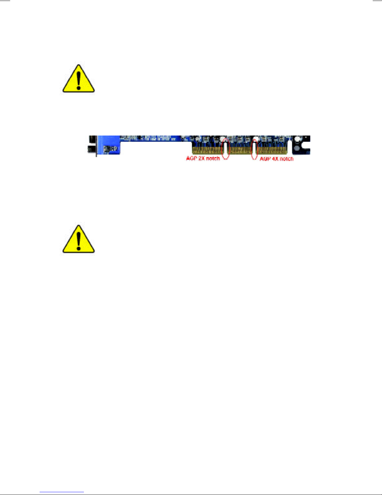
Whenyou installing AGPcard,please make surethefollowing
notice isfullyunderstood and practiced.IfyourAGPcardhas
"AGP4Xnotch"(showbelow),please make sureyourAGPcardis
AGP4X(1.5V).
Donotuse AGP2Xcard(3.3V)inthismotherboard.Itwill
burnand damagethemotherboardduetoIntel®845(E/G)/850(E)
chipsetcan'tsupportAGP2X(3.3V).
Example1:Diamond VipperV770 golden fingeriscompatiblewith2X/
4Xmode AGPslot. It can be switched between AGP2X(3.3V)or
4X(1.5V)mode byadjusting the jumper.The factorydefaultforthiscard
is2X(3.3V).If you install thiscardinGA-8IHXP(oranyAGP4Xonly)
motherboardswithoutswitching the jumperto4Xmode (1.5V),itwill
burnthe motherboard.
Example2:SomeATiRage 128 Prographics cardsmade by“Power
Color”,the graphics cardmanufacturer&someSiS305 cards,their
golden fingeriscompatiblewith2X/4Xmode AGPslot, buttheysupport
2X(3.3V)only.If you install thiscardinGA-8IHXP (oranyAGP4Xonly)
motherboards,itwill burnthe motherboard.
Note:Although Gigabyte'sAG32S(G)graphics cardisbased on ATiRage
128 Prochip,the design ofAG32S(G)iscompliancewithAGP4X(1.5V)
specification.Therefore,AG32S(G)will workfine withIntel®845(E/G)/
850(E)based motherboards.

MTheauthorassumes no responsibilityforanyerrors
oromissionsthatmay appearinthisdocumentnor
does theauthormake acommitmenttoupdatethe
information containedherein.
MThird-partybrandsand names arethepropertyof
theirrespective owners.
MPlease do notremove anylabelson motherboard,this
may voidthewarrantyofthismotherboard.
MDuetorapidchangeintechnology,someofthe
specificationsmightbeoutofdatebeforepublication
ofthisbooklet.

Declaration ofConformity
We,Manufacturer/Importer
(full address)
G.B.T.TechnologyTräding GMbH
AusschlagerWeg41,1F,20537 Hamburg,Germany
declarethatthe product
(description ofthe apparatus,system,installation towhichitrefers)
MotherBoard
GA-8IHXP
isinconformitywith
(referencetothe specification underwhichconformityisdeclared)
inaccordancewith89/336 EEC-EMCDirective
oEN55011 Limitsand methodsofmeasurement
ofradiodisturbancecharacteristics of
industrial,scientificand medical(ISM
high frequency equipment
oEN61000-3-2*
TEN60555-2
Disturbancesinsupplysystemscause
byhouseholdappliancesand similar
electricalequipment“Harmonics”
oEN55013 Limitsand methodsofmeasurement
ofradiodisturbancecharacteristics of
broadcastreceiversand associated
equipment
oEN61000-3-3*Disturbancesinsupplysystemscause
byhouseholdappliancesand similar
electricalequipment“Voltage fluctuations”
oEN55014 Limitsand methodsofmeasurement
ofradiodisturbancecharacteristics of
householdelectricalappliances,
portabletoolsand similarelectrical
apparatus
TEN50081-1Genericemission standardPart1:
Residualcommercialand lightindustry
TEN50082-1GenericimmunitystandardPart1:
Residualcommercialand lightindustry
oEN55015 Limitsand methodsofmeasurement
ofradiodisturbancecharacteristics of
fluorescentlampsand luminaries
Genericemission standardPart2:
Industrialenvironment
oEN55081-2
Immunityfromradiointerferenceof
broadcastreceiversand associated
equipment
Genericemission standardPart2:
Industrialenvironment
oEN55082-2
TEN55022 Limitsand methodsofmeasurement
ofradiodisturbancecharacteristics of
information technologyequipment
lmmunityrequirementsforhousehold
appliancestoolsand similarapparatus
oENV55104
Cabled distribution systems;Equipment
forreceiving and/ordistribution from
sound and television signals
EMCrequirementsforuninterruptible
powersystems(UPS)
oEN50091-2
oEN55020
oDINVDE0855
opart10
opart12
(ECconformitymarking)
TCEmarking
Themanufactureralsodeclares theconformityofabove mentionedproduct
withtheactualrequiredsafetystandardsinaccordance withLVD73/23 EEC
Safetyrequirementsformainsoperated
electronicand related apparatusfor
householdand similargeneraluse
oEN60950
oEN60065
Safetyofhouseholdand similar
electricalappliances
oEN60335
Manufacturer/Importer
Signature:
Name:
(Stamp)Date:May.31,2002
TEN60555-3
TimmyHuang
TimmyHuang
oEN50091-1

FCC Part15,SubpartB,Section 15.107(a)and Section 15.109
(a),Class BDigitalDevice
DECLARATIONOFCONFORMITY
PerFCC Part2Section 2.1077(a)
ResponsiblePartyName:
Address:
Phone/Fax No:
hereby declaresthattheproduct
ProductName:
Conformstothefollowing specifications:
Thisdevice complieswithpart15 oftheFCC Rules.Operation is
subjecttothefollowing twoconditions:(1)Thisdevice maynot
causeharmfuland(2)thisdevice mustacceptanyinferencereceived,
including thatmaycauseundesiredoperation.
RepresentativePerson’sName:
Signature:EricLu
SupplementaryInformation:
ModelNumber:
17358 RailroadStreet
CityofIndustry,CA 91748
G.B.T.INC.(U.S.A.)
(818)854-9338/(818)854-9339
Motherboard
GA-8IHXP
Date:
ERICLU
May31,2002

USER’SMANUAL
GA-8IHXP
P4Titan-RDRAMMotherboard
Pentium®4ProcessorMotherboard
Rev.2101
12ME-8IHXP-2101

2
GA-8IHXP Motherboard
Table Of Content
Item Checklist ......................................................................................... 4
WARNING! ............................................................................................... 4
Chapter 1 Introduction ............................................................................. 5
Summary of Features .................................................................................. 5
GA-8IHXP Motherboard Layout ................................................................... 7
Chapter 2 Hardware Installation Process ................................................ 8
Step 1: Install the Central Processing Unit (CPU)....................................... 9
CPU Installation ................................................................................................................. 9
CPU Heat Sink Installation .............................................................................................. 10
Step 2: Install memory modules ................................................................ 11
Introduce RIMM (Rambus In-line Memory Module) .................................................... 12
Step 3: Install expansion cards ................................................................. 13
Step 4: Connect ribbon cables, cabinet wires, and power supply ........... 14
Step 4-1: I/O Back Panel Introduction ............................................................................ 14
Step 4-2: Connectors Introduction .................................................................................. 16
Step 4-3: ATX 12V Power Supply Introduction ............................................................. 23
Chapter 3 BIOS Setup .......................................................................... 24
The Main Menu (For example: BIOS Ver. :F1) ......................................... 26
Standard CMOS Features......................................................................... 28
Advanced BIOS Features .......................................................................... 31
Advanced Chipset Features ...................................................................... 33
Integrated Peripherals ............................................................................... 37

3
Table of Content
Power Management Feature .................................................................... 43
PNP/PCI Configurations ............................................................................ 47
PC Health Status........................................................................................ 49
Set Supervisor / User Password ................................................................ 51
Load Optimized Defaults ........................................................................... 52
Load Fail-Safe Defaults ............................................................................. 53
Save & Exit Setup ....................................................................................... 54
Exit Without Saving .................................................................................... 55
Chapter 4 Technical Reference ............................................................ 56
Block Diagram ........................................................................................... 56
Dual BIOS / Q-Flash Introduction ............................................................. 57
Four Speaker & SPDIF Introduction.......................................................... 66
@ BIOS Introduction .................................................................................. 70
Easy TuneTM 4 Introduction ....................................................................... 71
Chapter 5 Appendix .............................................................................. 72
4
GA-8IHXP Motherboard
Computer motherboards and expansion cards contain very delicate Integrated Circuit (IC) chips. To
protect them against damage from static electricity, you should follow some precautions whenever you
work on your computer.
1. Unplug your computer when working on the inside.
2. Use a grounded wrist strap before handling computer components. If you do not have
one, touch both of your hands to a safely grounded object or to a metal object, such as
the power supply case.
3. Hold components by the edges and try not touch the IC chips, leads or connectors, or
othercomponents.
4. Place components on a grounded antistatic pad or on the bag that came with the
components whenever the components are separated from the system.
5. Ensure that the ATX power supply is switched off before you plug in or remove the ATX
power connector on the motherboard.
If the motherboard has mounting holes, but they don’t line up with the holes on the base and there are
no slots to attach the spacers, do not become alarmed you can still attach the spacers to the mounting
holes. Just cut the bottom portion of the spacers (the spacer may be a little hard to cut off, so be careful
of your hands). In this way you can still attach the motherboard to the base without worrying about short
circuits. Sometimes you may need to use the plastic springs to isolate the screw from the motherboard
PCB surface, because the circuit wire may be near by the hole. Be careful, don’t let the screw contact
any printed circuit write or parts on the PCB that are near the fixing hole, otherwise it may damage the
board or cause board malfunctioning.
Installing the motherboard to the chassis…
WARNING!
Item Checklist
!The GA-8IHXP motherboard ! GA-8IHXP User’s manual
!I/O Shield ! CRIMM x 2
!Quick PC Installation Guide ! Floppy cable x 1
!IDE cable x 3 ! USB cable x 2
!CD for motherboard driver & utility ! SPD-KIT x 1

5
Introduction
Form Factor "30.5cm x 24.4cm ATX size form factor, 6 layers PCB.
CPU "Socket 478 for Intel®Micro FC-PGA2 Pentium®4 processor
"Intel Pentium®4 400/533MHz FSB
"Support Intel®Pentium®4 (Northwood, 0.13
m) processor
"2nd Level cache depend on CPU
Chipset "Chipset 82850E HOST/AGP/Controller
"ICH4 I/O Controller Hub
Memory "4 184-pin RIMM Sockets
"Supports 4 x PC800 RIMM or 4 x PC1066 RIMM DIMM
"Dual direct RDRAM channel
"Supports up to 2GB (Max)
I/O Control "Winbond W83627HF
Slots "1 CNR(Communication and Networking Riser) Slot
"1 AGP support 4X(1.5V) device
"6 PCI slot supports 33MHz & PCI 2.2 compliant
On-Board IDE "2 IDE bus master (DMA33/ATA66/ATA100) IDE ports for up to 4
ATAPI devices
"IDE3 and IDE4 Compatible with RAID,Ultra ATA133/100.
On-Board Peripherals "1 Floppy port supports 2 FDD with 360K, 720K,1.2M, 1.44M
and 2.88M bytes.
"1 Parallel port supports Normal/EPP/ECP mode
"2 Serial ports (COMA&COMB)
"6 x USB 2.0/1.1 by ICH4
4 x USB 2.0/1.1by NEC D720100AS1
"1 IrDA connector for IR/CIR
Hardware Monitor "CPU/Power/System Fan Revolution detect
"CPU Overheat Warning
"System Voltage Detect
On-Board LAN "Build in RTL8100BL Chipset
On-Board USB 2.0 "NEC D720100AS1 Chipset
Summary of Features
Chapter 1 Introduction
to be continued......

6
GA-8IHXP Motherboard
On-Board Sound "Creative CT5880 Sound Chipset + Sigmatel 9708T CODEC
"4 channel audio CODEC
"Line In/Line Out/Mic In/Game Port/CD In/AUX IN/SPDIF
(5.1 channel)
On-Board RAID "Onbard Promise PDC20276
"Support data striping (RAID 0) or mirroring (RAID 1)
"Supports concurrent dual IDE controller operation
"Supports IDE bus master operation
"Displays status and error checking messages during boot-up
"Mirroring supports automatic background rebuilds
"Features LBA and Extended Interrupt13 drive translation in
controller onboard BIOS
PS/2 Connector "PS/2 Keyboard interface and PS/2 Mouse interface
BIOS "Licensed AMI BIOS, 4M bit FWH
"Supports Dual BIOS / Q-Flash / Multi Language
AdditionalFeatures "PS/2 Keyboard power on by password
"PS/2 Mouse power on
"External Modem wake up
"STR(Suspend-To-RAM)
"Wake on LAN
"AC Recovery
"USB KB/Mouse wake up from S3
"Supports @BIOS
"Supports EasyTune4
"Supports Face Wizard
Special Features "Over Voltage (RIMM/AGP/CPU)
"Over Clock (CPU/PCI/AGP)
#Please set the CPU host frequency in accordance with your processor’s specifications. We don’t
recommend you to set the system bus frequency over the CPU’s specification because these
specific bus frequencies are not the standard specifications for CPU,chipset and most of the
peripherals. Whether your system can run under these specific bus frequencies properly will depend
on your hardware configurations, including CPU,Chipsets,SDRAM,Cards….etc.
On-Board MS,SD,SC "Winbond SMART @I/O Chipset (Memory Stick , Security Digital
and SC header)
7
Hardware Installation Process
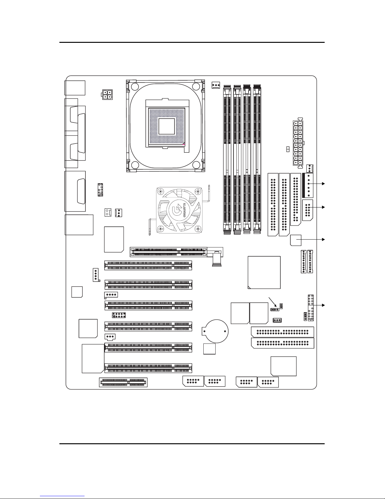
GA-8IHXP Motherboard Layout
KB / MS
COMACOMB
LPT
SOCKET478
PWR
FAN
MIC_IN LINE_OUT
LINE_IN
GAME
USB
LAN
ATX_12V
F_Audio
CPU_FAN
850E
W83627
AGP
PCI1
PCI2
PCI3
PCI4
CD_IN
SPDIF
CODEC
RTL
8100BL
CT5880 PCI5
PCI6
CNR F_USB3
PROMISE
20276
MS
IDE3
IDE4
BACKUP
BIOS
MAIN
BIOS
SD
F_PANEL
W83L
5180
BATTERY
ICH4
AUX
RIMM1
RIMM2
RIMM3
RIMM4
IDE2
IDE1
FDD
SC
RAM_LED
ATX
GA-8IHXP
P4 Titan 533
SYS_FAN
AUX_IN
IR_CIR
PWR_LED
CI
CLR_CMOS
WOL
NEC
F_USB4 F_USB1
F_USB2
NB_FAN
8
GA-8IHXP Motherboard
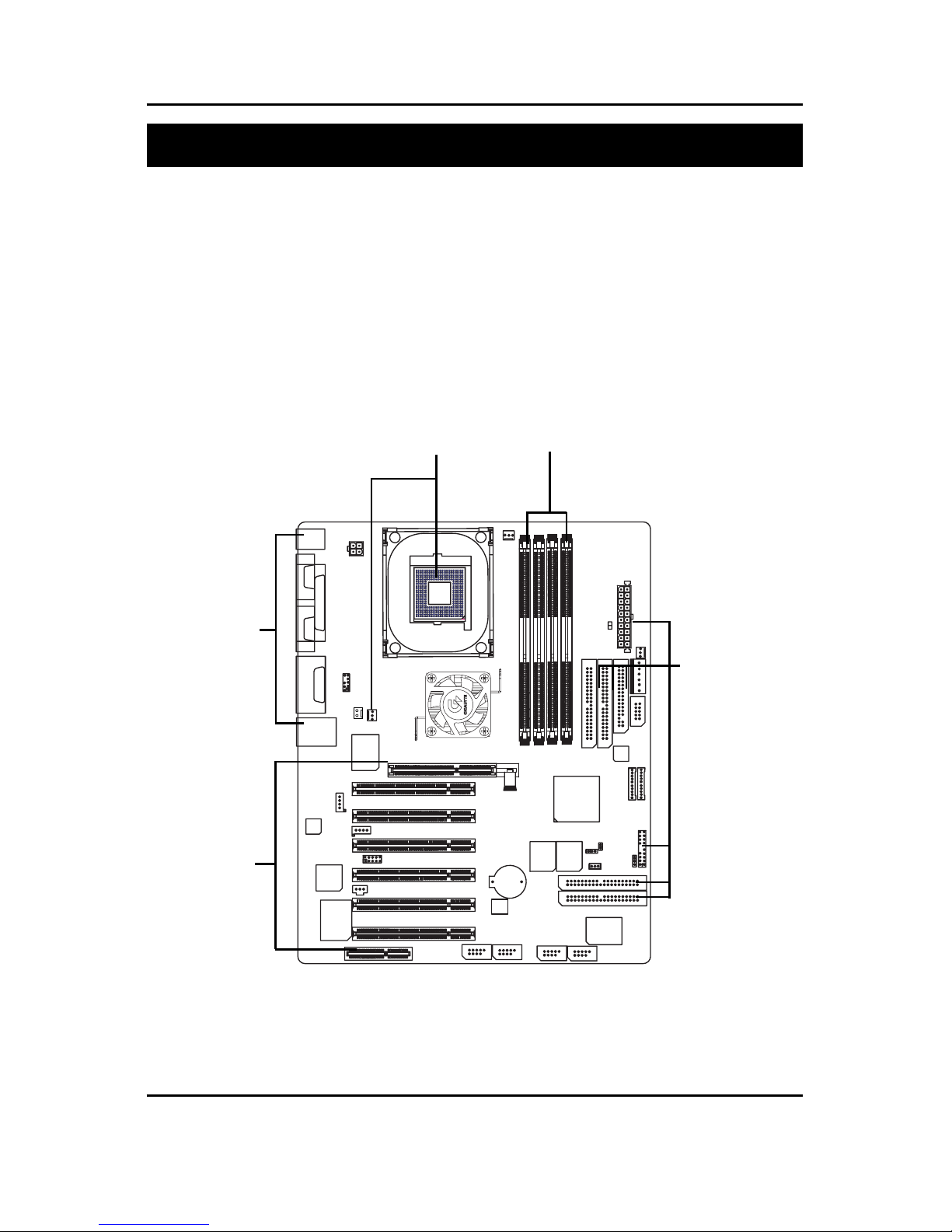
To set up your computer, you must complete the following setups:
Step 1- Install the Central Processing Unit (CPU)
Step 2- Install memory modules
Step 3- Install expansion cards
Step 4- Connect ribbon cables, cabinet wires, and power supply
Step 5- Setup BIOS software
Step 6- Install supporting software tools
Chapter 2 Hardware Installation Process
Step 1 Step 2
Step 4
Step 4
Step 3
9
Hardware Installation Process
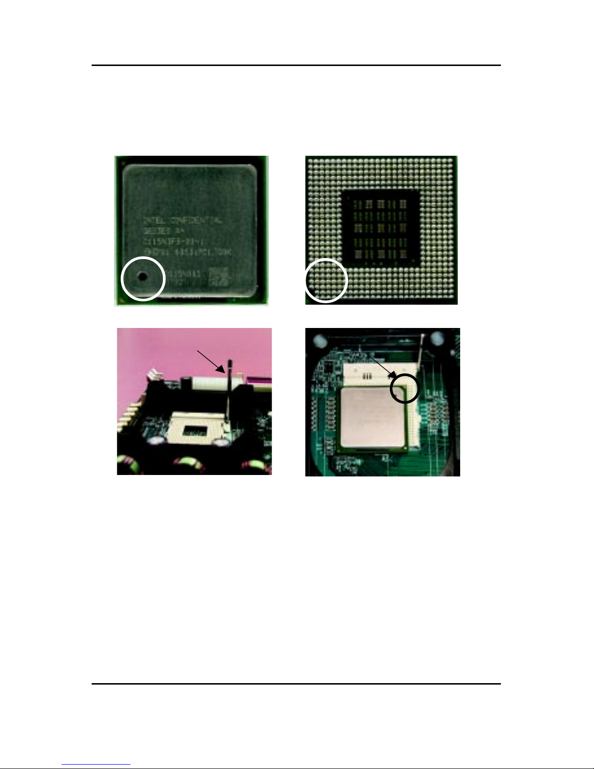
Step 1: Install the Central Processing Unit (CPU)
CPU Installation
##
##
#Please make sure the CPU type is supported by the motherboard.
Pin1 indicator Pin1indicator
CPU Top View CPU Bottom View
Socket Actuation Lever
1. Pull up the CPU socket level
and up to 90-degree angle.
Pin1 indicator
2. Locate Pin 1 in the socket and look
for a (golden) cut edge on the CPU
upper corner. Then insert the CPU
into the socket.
3. Press down the CPU socket lever and
finish CPU installation.
10
GA-8IHXP Motherboard
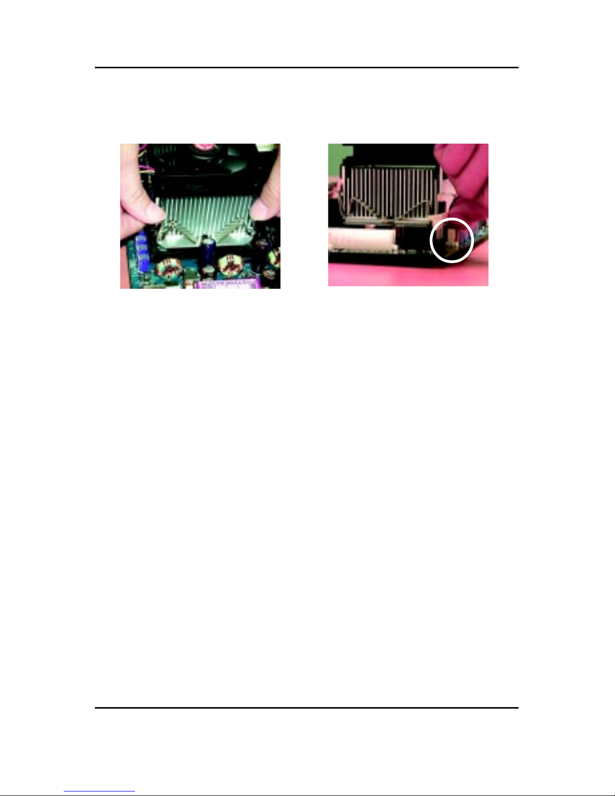
CPU Heat Sink Installation
1. Fastentheheatsinksupporting-base
onto the CPU socket on the main-
board.
2. Make sure the CPU fan is plugged
to the CPU fan connector, than
install complete.
##
##
#Please use Intel approved cooling fan.
##
##
#We recommend you to apply the thermal tape to provide better heat
conduction between your CPU and heatsink.
(The CPU cooling fan might stick to the CPU due to the hardening of the
thermal paste. During this condition if you try to remove the cooling fan, you
might pull the processor out of the CPU socket alone with the cooling fan, and
might damage the processor. To avoid this from happening, we suggest you to
either use thermal tape instead of thermal paste, or remove the cooling fan with
extreme caution.)
##
##
#Make sure the CPU fan power cable is plugged in to the CPU fan connector,
this completes the installation.
##
##
#Please refer to CPU heat sink user’s manual for more detail installation
procedure.
11
Hardware Installation Process
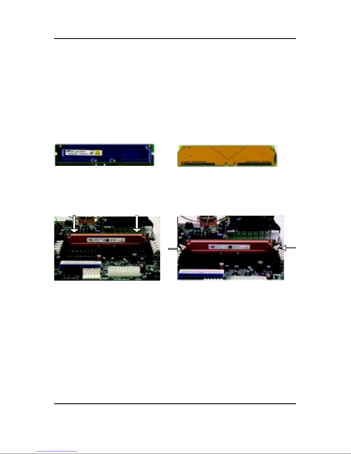
Step 2: Install memory modules
The motherboard has 4 Rambus In-line Memory Module (RIMM) sockets. The BIOS will automati-
cally detect memory type and size. To install the memory module, just push it vertically into the
RIMM Slot .The RIMM module can only fit in one direction due to the two notches. Please note; Both
RIMM modules inserted on RIMM1 and RIMM2 slots are recommended to have the same size,
frequency. If not, the larger sized module will l be automatically re-sized by BIOS to match the
smaller sized module. The same rule applies to both RIMM3 and RIMM4 slots.
You can insert two RIMMs or four RIMMs into RIMM slots, but C-RIMM (Continuity RIMM)
modules must be inserted into the empty slots.
Push the ejector tab towards the RIMM.
#When STR/RIMM LED is ON, you do not install / remove RDRAM from socket.
RIMM CRIMM
Check RIMM module if it is supported by the
M/B.
Insert the RIMM module into the slot.
12
GA-8IHXP Motherboard
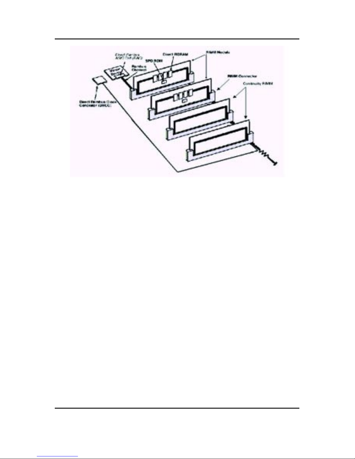
Introduce RIMM (Rambus In-line Memory Module)
Direct Rambus Memory Controller
!Directly support a Dual Direct Rambus * Channel
$Supports 300&400 MHz Direct Rambus * Channel @ 100MHz host bus frequency.
$Maximum memory array size up to 256MB using 64Mb/72Mb, 512MB using 128Mb/144Mb,
1GB using 256Mb/288Mb DRAM technology
!Supports up to 32 Direct Rambus devices per channel
!Supports a maximum DRAM address decode space of 4GB
!Configurable optional ECC operation
$ECC with single bit Error Correction and multiple bit Error Detection
$Single bit errors corrected and written back to memory (auto-scrubbing)
$Parity mode not supported
APIC memory space in hardware. It is the BIOS or system designer's responsibility to limit DRAM
population so that adequate PCI, AGP, High BIOS, and APIC memory space can be allocated.

13
Hardware Installation Process
Step 3: Install expansion cards
1. Read the related expansion card’s instruction document before install the expansion card into
the computer.
2. Remove your computer’s chassis cover, screws and slot bracket from the computer.
3. Press the expansion card firmly into expansion slot in motherboard.
4. Be sure the metal contacts on the card are indeed seated in the slot.
5. Replace the screw to secure the slot bracket of the expansion card.
6. Replace your computer’s chassis cover.
7. Power on the computer, if necessary, setup BIOS utility of expansion card from BIOS.
8. Install related driver from the operating system.
AGP Card
Please carefully pull out the small white-
drawable bar at the end of the AGP slot when
you try to install/ Uninstall the AGP card.
Please align the AGP card to the onboard
AGP slot and press firmly down on the slot .
Make sure your AGP card is locked by the
small white- drawable bar.
Issues To Beware Of When Installing CNR
Please use standard CNR card like the one in order to avoid mechanical problem.
Standard CNR Card
14
GA-8IHXP Motherboard
Step 4: Connect ribbon cables, cabinet wires, and power
supply
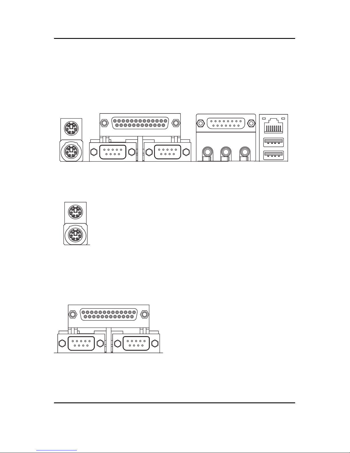
Step 4-1: I/O Back Panel Introduction
##
##
#PS/2 Keyboard and PS/2 Mouse Connector
$$
$$
$Parallel Port and Serial Ports (COMA/COMB)
PS/2 Mouse Connector
(6 pin Female)
PS/2 Keyboard Connector
(6 pin Female)
Parallel Port
(25 pin Female)
COMA COMB
Serial Ports (9 pin Male)
%This connector supports standard PS/2
keyboard and PS/2 mouse.
%This connector supports 2 standard COM ports
and 1 Parallel port. Device like printer can be
connected to Parallel port ; mouse and modem
etc can be connected to Serial ports.
#
$%
&
'

15
Hardware Installation Process
%%
%%
%Game /MIDI Ports
Joystick/ MIDI (15 pin Female)
''
''
'USB/LAN Connector
&&
&&
&Audio Connectors
%This connector supports joystick, MIDI keyboard and other
relate audio devices.
%After install onboard audio driver, you may connect
speaker to Line Out jack, micro phone to MIC In jack.
Device like CD-ROM , walkman etc can be connected
to Line-In jack.
%Before you connect your device(s) into USB connector(s),
please make sure your device(s) such as USB keyboard,
mouse, scanner, zip,speaker..etc. Have a standard USB
interface. Also make sure your OS (Win 95 with USB
supplement, Win98, Windows 2000, Windows ME, Win
NT with SP 6) supports USB controller. If your OS does not
support USB controller, please contact OS vendor for pos-
sible patch or driver upgrade. For more information please
contact your OS or device(s) vendors.
Line In
MIC In
Line Out
USB 0
USB 1
LAN
Connector

16
GA-8IHXP Motherboard
Step 4-2: Connectors Introduction
A ATX _12V L PWR_LED
B PWR_FAN M WOL
C ATX N IDE3/IDE4
D RAM_LED O F_USB1~4
E SYS_FAN P SPDIF
F AUX Q BATTERY
G MS/SD/SC R IR_CIR
H FDD/IDE1/IDE2 S AUX_IN
I CLR_CMOS T CD_IN
J CI U CPU FAN
K F_Panel V NB_FAN
W F_Audio
A
C
B
D
E
F
G
H
I
J
L
K
M
Q
R
S
T
N
O
P
G
U
V
W
Table of contents
Other G.B.T Motherboard manuals


