G-Mouse GPS Receiver User Manual
Page 4
1.3 Technical Specification
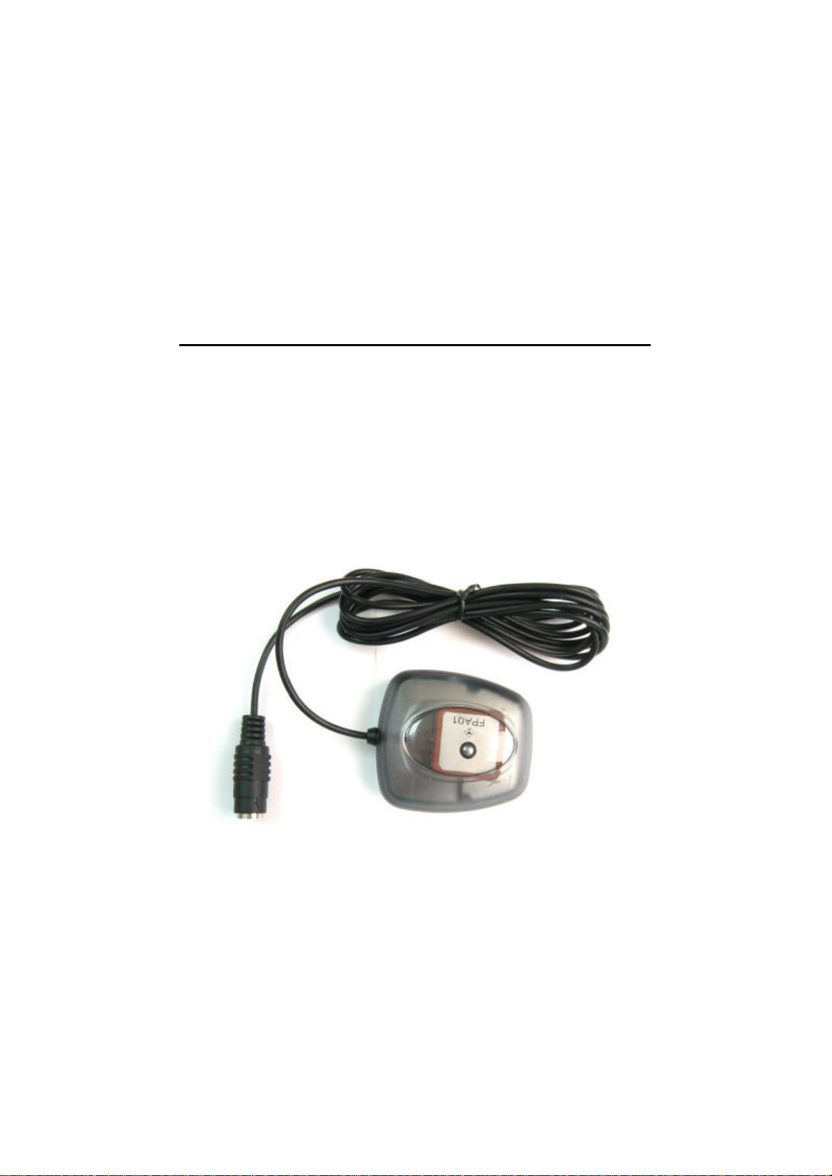
1.3.1 Dimension
Single construction integrated antenna/receiver.
Size:60.0 (L) x 54.0 (W) x 27.0(H) (mm)。
2.36(L) x 2.13 (W) x 1.06 (H) (Inch)。
1.3.2 Environmental Characteristics
1) Operating temperature: -10oC~70oC(internal)。
2) Storage temperature: -40oC~85oC
1.3.3 Electrical Characteristics
1) Input voltage: +4.75~+5.5V DC
1.3.4 Performance
1) Tracks up to 32 satellites.
2) Update rate: 1Hz.
3) Acquisition time (average)
Hot start: 1 sec
Warm start: 36 sec
Cold start: 37 sec
4) Position accuracy:
A) None DGPS (Differential GPS)
Position: < 3m CEP (50%) without SA(horizontal)
Time: 0.1ms synchronized GPS time
B) DGPS (Differential GPS)
Position: <2.5m
5) Dynamic Conditions:
Altitude: 18,000 m (60,000 feet)max
Velocity: 515 m/sec (700 knots)
Acceleration: 4G max
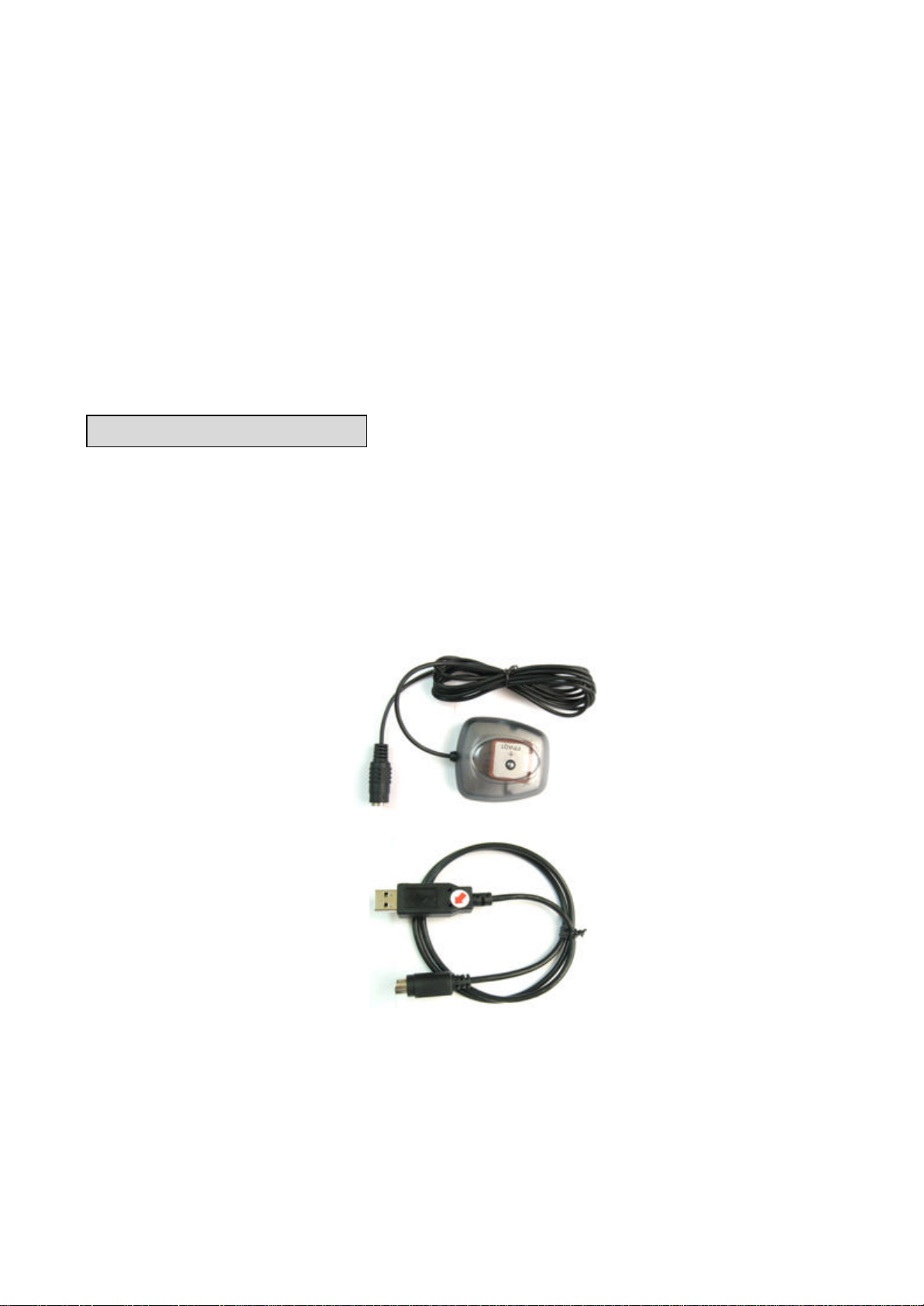
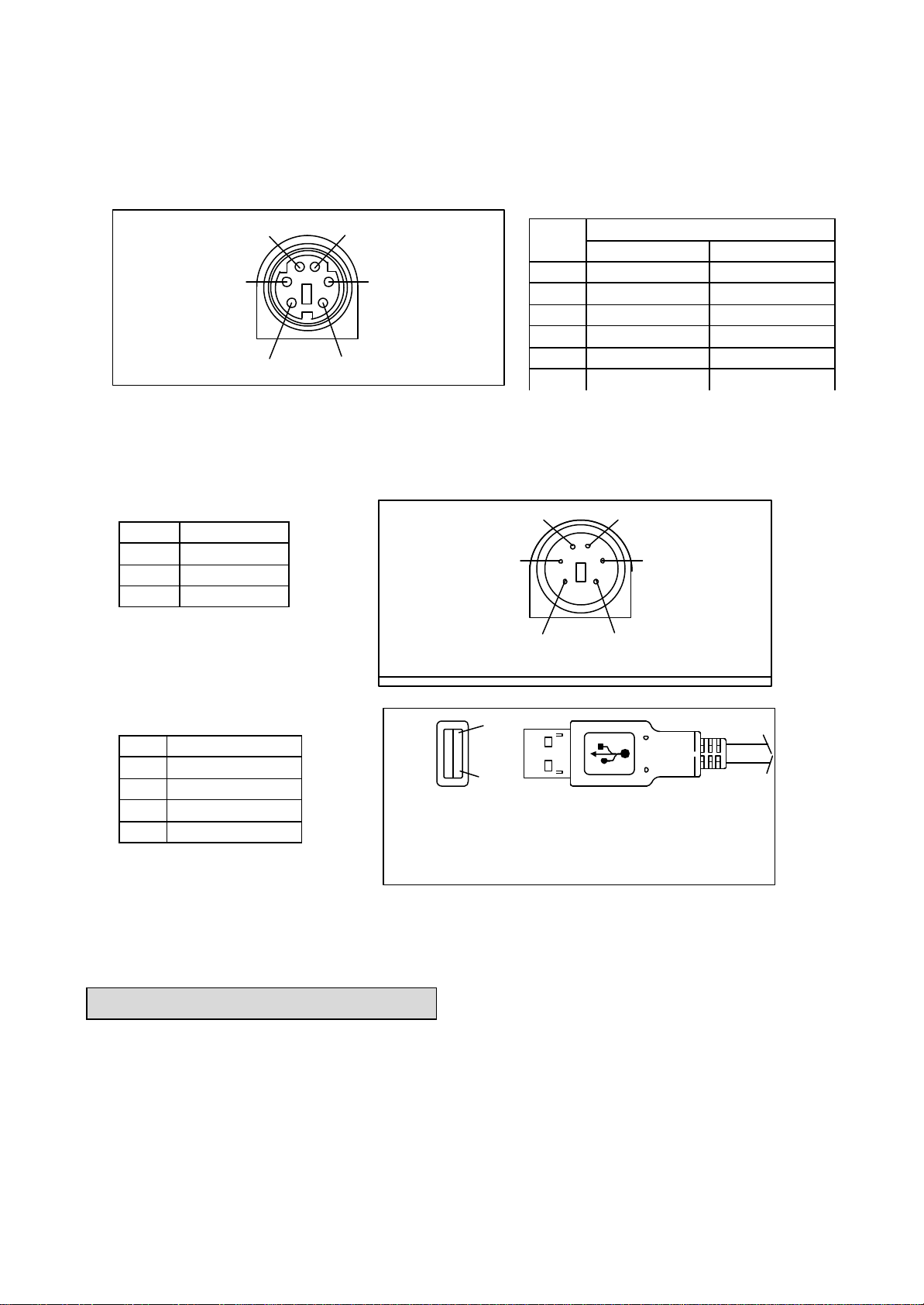
1.3.5 Interfaces
1) Dual channel RS-232 or TTL compatible level, with user selectable baud rate (4800, 9600-Default,
19200, 38400)
2) NMEA 0183 Version 3.01 ASCII output (Default:GGA,GSA,GSV,RMC,VTG,CHN).
2.Operational Characteristics
2.1 Initialization Setup
After the initial self-test is complete, the G-MR will begin the process of satellite acquisition and
tracking. The acquisition process is fully automatic and, under normal circumstances, will take
approximately 37 seconds to achieve a position fix (36 seconds if ephemeris data is know). After a
position fix has been calculated, valid position and time information will be transmitted over the output
channel(s).
The G-MRutilizes initial data such as last stored position, data and time as well as satellite orbital
data to achieve maximum acquisition performance. If significant inaccuracy exists in the initial data, or
if the orbital data is obsolete, it may take a long time to achieve a navigation solution. The G-MR
Auto-locate feature is capable of automatically determining a navigation solution without intervention
from the host system. However, acquisition performance can be improved if the host system initialized
the G-mouse following the occurrence of one or more of the following events: