GAOKIN E02 User manual

第- 1 - 页
E02(GK194MS)
Maintenance Manual
Edited:Li LinJun
Verified:Hu Xianyong
Approved:Li Xuelong

第- 2 - 页
Catalog
1 Overview..................................................................................................................................... - 3 -
1.1 product chracteristic................................................................................................................... - 3 -
1.2 Product application、specification and apllying range.............................................................. - 3 -
1.3 Model meaning .......................................................................................................................... - 3 -
1.4 Applying environment and working condition .......................................................................... - 3 -
1.5 Affect to environment and energy.............................................................................................. - 4 -
1.6 Safety ....................................................................................................................................... - 4 -
2 Product technical charateristic .................................................................................................... - 4 -
2.1 Main performance parameter..................................................................................................... - 4 -
2.2 Main structure parameter ........................................................................................................... - 5 -
2.3 Transmission system parameter ................................................................................................. - 6 -
2.4 Fuel and lubricating oil parameter ............................................................................................. - 7 -
2.5 Coolant parameter...................................................................................................................... - 7 -
3. Engine outline drawing.............................................................................................................. - 7 -
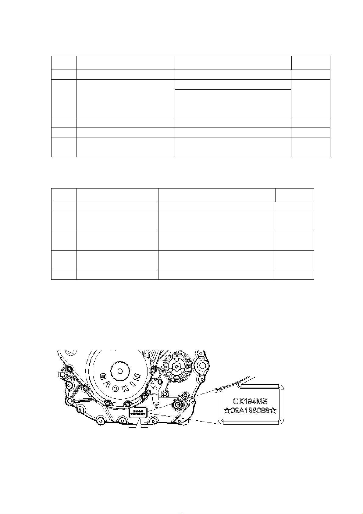
3.1 Engine model and countermark position.................................................................................... - 7 -
3.2 E02 engine outline drawing ....................................................................................................... - 7 -
4.Engine assembly requirement and accessory............................................................................ - 8 -
4.1 Engien assembly ........................................................................................................................ - 8 -
4.2 Inlet and exhaust system ............................................................................................................ - 8 -
4.3 Fuel supply system..................................................................................................................... - 9 -
4.4 Coolant system......................................................................................................................... - 10 -
4.5 Electrical equipment system .................................................................................................... - 10 -
4.6 EFI system.................................................................................................................................- 11 -
5.Engine usage、maintenance and fault solution………………………………………………- 13 -
5.1 Engine using and cautions........................................................................................................ - 14 -
5.2 Maintenace............................................................................................................................... - 16 -
5.3 Common fault check list .......................................................................................................... - 20 -
Annex files…………….................................................................................................................... - 25 -
Annex 1E02 outline drawing...................................................................................................... - 26 -
Annex 2Carburetorwireconnectingdrawing ............................................................................ - 27 -
Annex 3EFI wire connecting drawing........................................................................................ - 28 -
Annex 4Carburetorwiresandconnectormodel ........................................................................ - 29 -
Annex 5EFIwiresandconnectormodel ..................................................................................... - 30 -

第- 3 - 页
1Overview
1.1Enginecharacteristic
GK194MS engine works stable, with high torque, long life, low consumption, can be
used in wide range.
1.2Types、application、Specification
GK194MS engines including two series E02、E03 and 8 models,E02 is the engine with
gears. It is applied to two wheels motorcycles、sports ATV、applicability ATV、UTV。
Details please refer to the following table:
S/N Product
code Model Feature Remark
1 E02C 194MS Carb.、manual clutch、pedal
shifting (5forward shifts)
Used on two wheels
vehicle
2 E02C-2 194MS-A EFI 、 manual clutch 、 pedal
shifting (5forward shifts)
Used on two wheels
vehicle
3 E02F 194MS-2
Carb.、manual clutch、pedal
shifting (4forward shifts+1
reverse)
Used one ATV
4 E02F-2 194MS-2A
EFI 、 manual clutch 、 pedal
shifting(4forward shifts+1
reverse)
Used one ATV
1.3Modelmeaning
1.4Operatingenvironmentandworkingcondition
Working environment temperature,engine with carburetor -10~40°C;engine with

第- 4 - 页
EFI(with battery above 45A.h)-30~40°C。
Apply to sea level elevation,engine with carburetor in 4000m;engine with EFI in 5000m。
Engine must be installed and fixed on vehicle or testing-bed, assembled all
accessories and filled in enough correct lubricating oil and coolant.
1.5Effecttoenvironmentandenergy
Polluted air like COx、CxHy、NOx will be emitted when engine works and consumes
fuel.
1.6Safety
The temperature of working engine is high, people are not allowed to touch engine
to avoid scald.
Engine output shaft is a high speed spinning part, please install protecting plate
or cover to avoid hurt.
2Producttechnicalcharacters
2.1Mainperformanceparameters
S/N Items Parameter/Description Remark
1. Working temperature
range °C
Engine with carb.-10~40
Engine with EFI ( matched with
batter above 45A.h y)-30~40
2. Height applied to m
Engine with carb. in 4000m
Engine with EFI in 5000m
3. Max. net power kW@r/min 27.5@5750 (10h running-in with
hi
g
h shift
)
4. Calibrating power ——
5. Max. net torque N.m@r/min 51.5@4250 (10h running-in with
hi
g
h shift
)
6. Min. fuel consumption
g/
kW.h ≤300 WOT
7. Max. RPM r/min 6500

第- 5 - 页
S/N Items Parameter/Description Remark
8. idling r/min 1500±150
9. Exhaust limited Carb. Euro II,EFI Euro.III Vehicle
calibrating
10. Noise limited Db(A) ≤80 Vehicle
calibrating
2.2Mainstructureparameter
S/N Items Parameter/Description Remark
1 Type Vertical、1 cylinder、SOHC、4 Stroke 、4
valves、water cooling
2 Outline size(L x b x h)mm
E02C E02F
380x420x500
3 Net weight kg 49 50
4 Bore diameter mm 94
5 Piston stroke mm 85
6 displacement ml 589.9
7 compression 9.7:1
8 Ignition mode Storage power supply、ignition coil
i
g
nites
9 Fuel supply Carburetor or EFI
10 Air inlet mode Naturally aspirated
11 Crankshaft rotating
direction Rotate to right
12 Valve transmission type Roller crossed rocker
13 Valve clearance mm Inlet valve 0.09~0.14
Outlet valve 0.17~0.22 Cool state
14 Lubrication mode pressure、splash
15 Starting mode electric

第- 6 - 页
S/N Items Parameter/Description Remark
16 Water pump flow L/min ≥90(runoff type 5000r/min)
17 Water coolant volume ml 200 Water
j
acket
18 Thermostat ℃ open/full open 71/85
19 Fuel pump flow L/min 4.39 (1000r/min)
20 Fuel pressure -
21 Fuel filter Pater-type
22 Fuel volume L 2.3
23 Generator output 14V 330W (5000r/min)
24 Starting generator power 12V 650W
25 Spark plug mm model:NGK CR7E,clearance:0.7~
0.8
2.3transmissionsystemparameter
The follow table shows E02 engine transmission parameter
S/N Items
Parameter/Description
Remark
E02C E02F
1. Clutch type Manual wet-type oil bath multiple
chi
p
s t
yp
e
2. Power output mode Chain wheel、chain link
3. Chain parameter 530type 15teeth
4. Transmission type Mechanical、5shifts
5. Gear shift order 1-N-2-3-4-5 R-N-1-2-3-4 Reverse
limited
6. Each shift transmission
ratio
1shift 6.029 reverse 4.854
Primary
transmissi
on ratio
2.345
2shift 3.846 1 shift 4.983
3shift 2.814 2 shift 3.4
4shift 2.244 3shift 2.558
5shift 1.876 4shift 1.97

第- 7 - 页
2.4Fuelandlubricatingoilparameter
S/N Items Parameter/Description Remark
1. Fuel grade 93#
2. Lubricating oil grade
-10~40°C,API 10W/40-SG or SH Recommend
to Use
mineral
oil
-20~40°C,API 5W/40-SG or SH
3. Lubrication oil consumption ≤5g/(kW.h)
4. Lubricating oil total volume 2.30 L
5. Lubricating oil max.
temperature 120°C
2.5watercoolantparameter
S/N Items Parameter/Description Remark
1. Coolant specification Antifreeze -30℃
2. Coolant volume ml 200 Water
jacket
3. Coolant inlet
temperature °C ≤90
4. Coolant outlet
temperature °C ≤105
5. Thermostat Open /full open 71/85℃,lift 3.5mm
3.Engineoutline
3.1Enginemodelandcountermarklocation
E02engine,please look at engine left side
3.2E02engineoutlinedrawing
See attached file 1 E02outline drawing (EFI)

第- 8 - 页
4.Engineassemblyrequirementandaccessory
Choose and install proper accessory on engine to ensure the engine get best performance. The
followings are engine accessory, we can match for customer, or customer can choose from the table by
themselves.
4.1Engineassembly
S/N Items Parameter/Description Remark
1) Assembly dip angle allowed 15(±0.5)°
Bore center line
and vertical
axis
2) Suspension fixed mode Three-point fixed, hard
connect
3)
E02
Front suspension hole
diameter、coordinate
Φ11(374.5,-23.5)
Φ11(355,-92.5) To main fixed hole
4) Rear suspension hole
diameter、coordinate
Φ11(35.5,116.5)
Φ16(0,0)、
Φ11(30.5,-132.5)
To main fixed hole
5) Top suspension hole
diameter、coordinate Φ9(211.3,248.8) To main fixed hole
4.2Inletandexhaustsystem
S/N Items Parameter/Description Remark
1)
Air filter A
Structure Box type with exhaust gas
connector
2) Model 17100-E02-0000
3) original
resistance Pa 1685
4)
Air inlet rate
m 3/h 300
5) volume L 4.5
6) Filter element Foam type
7)
Air filter B
Structure Box type with exhaust gas
connector、scaven
g
e
p
ort
8) Model 17100-E02-00A0
9) original
resistance Pa 1685

第- 9 - 页
S/N Items Parameter/Description Remark
10)
Air inlet rate
m3/h 300
11)
Connecting tube
Small end internal diameter
(throttle valve) ≥ Φ 40mm ,
length about 140mm
12) volume L 4
13) filter element Paper and foam
14)
muffler
Model 18000-E02B-00C0
15) Exhaust
back
p
ressure - Exit 100mm
16) original
resistance Pa -
17) Pipe diameter mm Inner diameter ≥ Φ34
18) Pipe length mm 625(or 1225)
19) Volume L 4.5
20) accelerant No
4.3fuelsupplysystem
S/N Items Parameter/Description Remark
1)
Carburetor
A
(with air
filter A)
structure Equal vacuum membrane type
2) Model KINZO PD42J
3) Stroke mm 30
4) Oil supply L -
5) Mouth
diameter mm Φ42
6) Oil pipe inner
diameter mm Φ7
7) Accelerating
p
um
p
No
8) Carburetor
B
(with air
Structure plunger type
9) Model Dellorto PZ40

第- 10 - 页
S/N Items Parameter/Description Remark
10)
filter B)
Stroke mm 35
11) Oil supply L -
12) Mouth
diameter mm Φ40
13) Oil pipe inner
diameter mm Φ7
14) Accelerating
bum
p
yes
15) Electric injector supply oil See 4.5
4.4Coolantsystem
S/N Items Parameter/Description Remark
1)
radiator
Structure Integration thermo switch、liquid adding
hole、pressure regulating valve
2) Model 19600-E02B-00A0
3) Radiating area -
4) Thermo
switch ℃ starting temperature 65
5) Pressure
control bar Starting pressure 0.9
6) Water tank
volume ≥20% total volume
7)
Inlet/outlet
water
pressure
difference Pa
-
8) Water pipe
inner diameter Φ19
9)
Fan
Model 19100-E02B-00A0
10) Power W ≥80
11) Air volume
m3
/
h -
4.5Electricappliancesystem
S/N Items Parameter/Description Remark

第- 11 - 页
S/N Items Parameter/Description Remark
1) Wire connection(electric)
schematic diagram
See annex 2(carburetor)、annex
3(EFI)
2)
igniter
(carburetor)
structure Digital control electric
ignition
3) Install
requirement
fixed、far away exhaust pipe、
ventilate good
Can be shielded
external
4) Model 33200-E02B-0001
5)
Ignition coil
Structure Open magnetic circuit ,
inductance
6) Model Delphi 28140972
7) Ignition
ener
gy
m
J
≥15
8)
High
voltage
wire mm
450,with shielding line
9) Spark plug K
Ω Damping electric resistance 5
10)
rectifier
Structure Three phase full wave rectifier
11) Model 32100-E02B-0000
12) Install
re
q
uiremnet
fixed、far away exhaust pipe、
ventilate
g
ood
Can be shielded
external
13) Regulate
volta
g
eV 14.5±0.5
14) Max.
current A 25
15) storage battery ≥12V14A.h
16) Motor connecting line Line dia. ≥10mm2
17) Wires and plugs model Annex 4(carburetor)
Annex 5(EFI)
4.6EFISystem
S/N Items Parameter/Description Remark
1) Wire connecting schematic
dra
g
ram See annex 3
2) System detail Delphi MT05 EFI system , small
volume,reliability。

第- 12 - 页
S/N Items Parameter/Description Remark
3)
ECU
Structure 36 needle pin,pin definition see
wire connection schematic diagram
4) Install
requirement
Shock proof:fixed on vehicle frame
Water proof:dry,difficult to get
wet,connector adown;
Anti high temperature:surroundings
max. temperature lower than 85℃;
Anti electromagnetic interference:
150mm awa
y
from s
p
ark
p
lu
g
5) Throttle
valve
(with air
filter B)
Structure Integration valve block、location
sensor、idlin
g
actuator
6) Max.
corner ° 84(tie piece stroke about 27.4mm)
7) Valve
diameter mm Φ40
8) Intake pipe Structure Integration fuel injector、intake
air temperature /pressure sensor
9) Fuel injector Install
requirement
Follow intake tube assembly
angle(wire connector face to engine
side)
10)
Fuel pump
Structure
Integration rough strainer
( particle diameter ≤ 40 μm)、
pressure regulating valve(pressure
250kPa)
11) Flow L/h ≥33
12) Install Oil tank low if possible, be aware
of leakage
13) pipeline
Inner diameter φ 6high voltage
multiple tube(withstand voltage≥
7bar)
14) Fuel fine filter
Particle diameter ≤10μm (no more
than ≤20μm) Connector diameterφ
8,flow more than 40L
15) Oil level sensor No
16) Relay Two pieces 30A、to control oil pump
and actuator separately

第- 13 - 页
S/N Items Parameter/Description Remark
17) Engine RPM signal output
Connect to vehicle instrument ,
12Vsquare wave,rotate each 1(duty
ratio about 50%,high level about
12V,low level about 0V;current
less than 30mA)。
18) Water temperature alarm
out
p
ut Without
19) O2 sensor per requirement
Distance to engine exhaust port
200-500mm、straight reach、upward
(water level included angle≥15°)
Refer to
4.6-01
20) Fault indicating lamp
Wire K output 12V to driving
indicator light, current less than
1A
21) Diagnostic apparatus
connector
6p connector , can connect with
diagnostic apparatus and status
monitoring
Fuel circuit connecting instruction(refer to 4.6-2):
Three direct links(A connector)+fuel fine filter + fuel pump oil-let,
Three direct links(B connector)+oil pump return opening +250kPa air-vent valve(oil
pump integration),
hd lk
(
)
l
.Picture4.61
. Picture4.62

第- 14 - 页
5.Engineusage、maintenanceandfaultsolution
5.1Engineusageandcautions
5.1.1 Engine Running-in
Check oil level with oil level window lines. If the oil level lower than the
underline, add fuel to the upper line.
It is not allowed to increase load at cold engine state, preheating engine for
1-3 minutes first.
Engine running-in is very important, new vehicle should drive at 75% speed of each
shift and shift gear often, if running-in not good, more faults will be increased.
Maintain the engine after driving 300km and 1000km, improve the engine working
condition to ensure good engine performance. Maintain the engine after every driving
3000km.
Running-in of engine is very important. 1000 km is stipulated as running-in mileages.
Running maintenance please refer to 5.2
Mote During the running-in, shift gear often and RPM should be no more than 70%
of max. RPM, accelerator should be no more than 70% of accelerator full opening.
Prohibit It is not allowed to make engine running at big accelerator with idling

第- 15 - 页
high speed。
5.1.2 Engine starting
Prohibit The engine can be only started with electricity. It is not allowed to press the
electric start button for a long time.
Start engine in N-shift. If it is not in N-shift, ensure the clutch is off before starting
engine.
Starting time should be no more than 5s each time, continuous starting should not
over 5 times and interval should be no less than 10s.Engine starting failed in 5 continuous
times, it would be regarded as engine starting fault.
1)Engine with carburetor, Starting when engine at cold state, close choke valve and
open the throttle properly, after the engine started, reopen the choke valve.
2)Engine with EFI system,it takes about 10s to do self-checking before starting
Warn It is not allowed to start engine before EMS self-checking finished
After engine started, preheating for 1-2 minutes at idling speed, avoiding to work in high
RPM with high load.
Note The electric control system of the engine must work with engine against reverse
ignition function. Or it might cause starting system damaged( such as starting gear、shaft、
one-way clutch, motor etc.)
5.1.3 Idling working and adjustment
Idling speed has been adjusted when left factor. If adjust idling speed again, ensure the
engine is hot and locate at N shift, spin carburetor idling adjustment screw, make the idling
stabilized at 1500±150r/min. If adjusting the screw can’t reach the requirement, you can
adjust carburetor mixed ratio.
Engine with EFI, adjusting throttle valve idling screw is not suggested. It should
be performed with the guidance of expert.
5.1.4 Accelerating working
Avoiding to increasing accelerator rapidly when engine accelerates, it is
suggested to increase stable. Engine RPM、shift and speed should match well during
driving.
warn A. Engine Working at high shift low RPM should be avoided
B. Engine Working at low shift high RPM for a long time should be avoided
5.1.5 Clutch operation

第- 16 - 页
E02 engine clutch operation structure is chain rack mechanism, when rack
strokeis1.5mm the clutch separated. It is not allowed to over pull clutch control
arm, or rack will come out of chain or clutch movable locked, which will lead to clutch
failure.
The engine clutch working stability is not very good at low RPM, when RPM less
than 3500r/min,Or When refuel or oil return, it is normal if clutch makes “dada”
noise. when RPM stable, the noise will disappear.
Note It is not allowed to use clutch when it is in a half clutch state
Forbid It is forbidden clutch works in a half clutch state, it will lead to clutch
abraded or damaged in a short time
5.1.6 Gear shift operation
E02 engine with 5 gearshifts, shift way is international, catch or step by left
foot, the order is: 1-N-2-3-4-5,neutral position Nis between shift 1 and shift 2,
it only takes half shift。If reverse shift is set, reverse shift R will occupy shift
1,2 to 5 will be changed as shift 1 to shift 4,the order will be changed to be
R-N-1-2-3-4。
Note Engine gearshift operation should work with coordination of accelerator,
clutch and shifting structure.
Warn A. It is not allowed gear shift when the clutch is on and without reducing throttle!
Or it might cause transmission parts damaged.
B. Stopping vehicle, disconnected reverse limited stopper and change into
reverse shift. Reverse limited stopper must be locked when vehicle at other
shifts
5.1.7 Engine stops
Note engine should keep idling for 1-2 minutes before stopping. After stopping
engine, don’t turn off power immediately, let radiator fan keep working until the
coolant temperature dropping to 80℃,fan stops working and turn off power.
5.1.8 Engine load
Max. load of engine:no more than 500kg。
5.2Maintenance
5.2.1 Engine lubrication system maintenance

第- 17 - 页
1)Check before using Check the oil level before starting,ensure the oil is at
normal level, look at oil view window, oil level should be between under and
above carved lines, it is better to be at the middle. If oil level is lower
than the under line, oil should be filled in to above line. Lubricating oil
choosing, please see annex 5
2) Lubrication maintenance and replace circle
Replace
circle km
300 800 2000 5000 Every
5000
Every
10000
Lubricating
oil G. G. G. G. G.
Oil filter
element G. G. G. G.
thick
filter
screen
Q. Q. Q. Q. Q.
Magnet ring Q. Q. Q. Q. Q.
Note:G. replace Q.Clean
Remark :replace oil filter element can’t be used again
3) Replacement operation
a) Dismantle oil pan nut:
b) filter element replacement picture:
E02 series:
5.2.2 Engine cooling system check and maintenance
forbid Cooling water (antifreeze solution) is poisonous and corrosive, it is not allowed
Use10#Thexagonal socket wrench to dismount
filter cover, replace oil filter element, use
fastening torque10-14N.m to assemble
Use 12mmhexagonal head wrench to dismantle

第- 18 - 页
to drink
Note A. This operation must be done at cold or low temperature.
B. if it is stick to painting surface careless, please wash and clean it with water
1) Cooling water check, put vehicle on the ground, check if the water level is
between above and under carved lines, it is better to be at the middle. If not, please
add water. Unscrew plug-hole bolt, normally there should be water overflow. Refer to
picture :
2)Cooling water mix ratio table
Lowest temperature Antifreeze agent V% Distilled water V%
-9℃ 20 80
-16℃ 30 70
-25℃ 40 60
-37℃ 50 50
-44.5℃ 55 45
Cooling water should mix according to local temperature, details see table
5.2.3 Valve adjustment
Engine valve clearance has been adjusted when left factory. Adjust the valve clearance
to specified value when it is abnormal (cylinder overheat or abnormal sound)
5.2.4 Air filter
If use filter paper type air filter element, replace filter element every driving 8000km. if
Water Outlet hole bolt

第- 19 - 页
other type of air filter element, please refer to supplier’s maintenance manual. In dusty
condition, shorten driving distance to replace. In a word, air intake must keep unobstructed
and clean
5.2.5 carburetor/throttle valve
Check and wash carburetor every driving 5000km
5.2.6 Fastener maintenance
1) Main fastener torque
S/N Designation Name Spe
c
Torque
(N·m)
Assembly
position
thread
agent
1 Q/QD921.4 Plate bolt grade 8.8 M6 10±2 All
2 Q/QD920 Plate bolt grade 10.9 M6 12±2 All
3 Q/QD920 Plate bolt grade 10.9 M8 25±3 All
4 GB/T819.1-2000 Cross-shaped plate screw M5 6±1 All ○
5 GB/T6177.1-2000 Hexagon flange nut M6 10±2 All
6 GB/T6177.1-2000 Hexagon flange nut M8 20±3 All
7 GB/T70.1-2000 Hexagon socket head cap
screws M6 x25 M6 10±2 Tightener
8 90302-E02-0000 Valve clearance adjusting
nut M5 7±1 Inlet/outlet
rocker
9 11001-E02-0000 View hole cover M39 18±3 Oil pan cover
Left front cover
10 11002-E02-0000 Top View hole cover M14 8±1 Left front cover
11 14402-E02-0000 Rocker shaft cover
bolt M14 25±3 Cylinder head
cover
12 3330-E02-0000 Spark plug M10 12±1 Cylinder head
13 36540-E02-0000 Water temperature
sensor M12 20±3 Cylinder head
14 90108-E02-000 Step bolt M6x12 M6 12±2 Driving chain ○
2) Fastening parts torque as following:
S/N Name & specification Torque value referenced
1 5mm bolt and nut 4.5~6
2 6mm bolt and nut 8~12
3 8mm bolt and nut 18~25
4 10mm bolt and nut 30~40
5 12mm bolt and nut 50~60

第- 20 - 页
6 5mm screw 3.5~5
7 6mm screw 7~11
8 6mm plate bolt and nut 10~14
9 8mm plate bolt and nut 20~30
10 10mm plate bolt and nut 30~40
5.3commonfaultsolution
1)、5.3.1 Starting difficult or unable starting
Item Cause Solution
Operate Improper operation Operate per instruction
Fuel supply
No fuel
No fuel in tank Add fuel
Fuel tank switch closed Open fuel tank switch
Fuel circuit blocked Wash、clean fuel circuit
Replace fuel filter
Carburetor blocked Clean carburetor
Fuel pump not working Check electric system
Fuel pump fault(EFI) Replace fuel pump
Fuel injector blocked(EFI) Wash or replace
Fuel pressure low (EFI)
Check fuel pipe connection
Check pressure, replace
fuel pump
Fuel quality、contain moisture Use new fuel
Fuel deposited for too lone Use new fuel
Too much fuel in combustor
Close oil tank, let engine
idle for 20 ~ 30s , to
remove deposited fuel
Gas mixture too strong or too rare Adjust carburetor mixing
ratio
Starting
system
storage
batter
energy not
enough
Storage battery volume not
enough
Choose battery per
recommendation
Battery self discharge 、
loss,low pressure
Replace battery or
charging again
Charging not enough in use
or not charging
Check charging 、 replace
rectifier
Starting motor electric supply not enough
(low RPM)
Choose connecting wire per
recommendation
This manual suits for next models
1
Table of contents
Popular Engine manuals by other brands

Briggs & Stratton
Briggs & Stratton 83100 Operator's manual

CRX Turbines
CRX Turbines SW Brushless Series Operation manual

TERASAKI
TERASAKI T2MC12-B instruction manual

STEPCRAFT
STEPCRAFT MM-800 Operating and safety instructions

Mercury
Mercury 305 CID Service manual

Briggs & Stratton
Briggs & Stratton Vanguard 540000 Series Operator's manual