Gates CARTRITAPE II Instruction Manual
I.AJ t
F"Yn
7-
/r-c,p
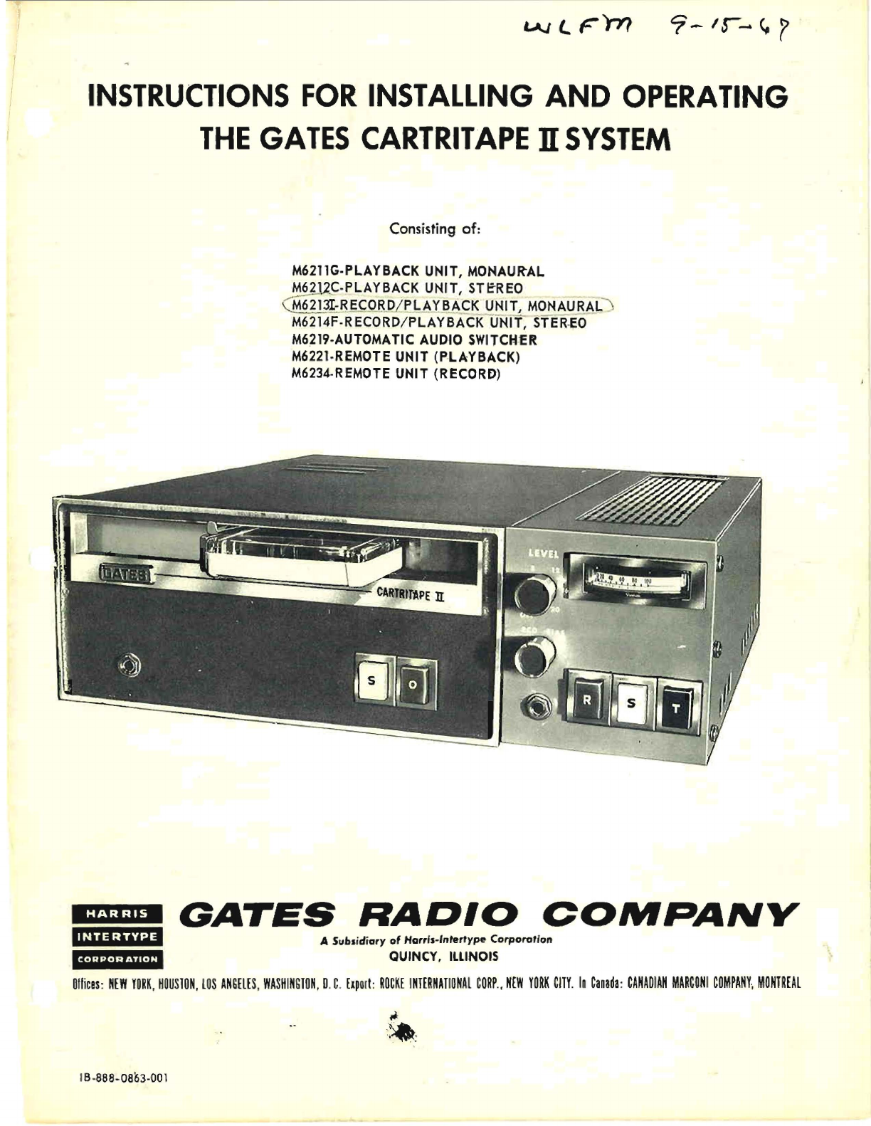
INSTRUCTIONS
FOR
INSTALLING
AND
OPERATING
THE
GATES
CARTRITAPE
n
SYSTEM
HARRIS
INTERTYPE
CORPOR
ATION
Consisting
of
:
M6211G·PLAYBACK UNIT, MONAURAL
M6
~
U.~.
PLAYBACK
UNIT, STEREO
~
213I-REC
QB.QLf1.AYJL~
CK
_
~~I~
MONAU
_
~
AL
M6214F·RECORD/PLAYBACK
UNIT,STER
.
EO
M6219·AUTOMATIC AUDIO
SWITCH
·
£R
M6221·REMOTE UNIT (P·
LAYBACK)
M6234·REMOTE UNIT (RECORD)
GATES
RADIO
COMPANY
A Subsidiary
of
Harr's·'ntertype
Corpororion
QUINCY, ILLINOIS
Ollices
:
NEW
YORK
.
KOUS10N,
lOS
ANGELES
,
WASHIHG10N
,D.C.
Elporl:
ROCKE
I
NTERNATIONAL
CORP
.•
H[W
YORK
CITY
.
In
Canada
:
CANADIAN
MARCONI
COMPANY
,
MONTREAL
18-888-0863-001
,J.:
:
~
,

2
TECHNICAL
DATA
System
frequency
Response:
:!:.2
db
from
50
cps
to
12Kc
'
:!:.4
db
from
-50
cps
to
15
Kc
[qualization:
Standard
NAB
Curve
Harmonic
Disto
rtlon:
Less
th
a n
1%
at
normal
record
level
(limited
by
tape)
Noise
:
-so
db
Wow
and
Flutter:
0 , 2%
maximum
Output
Level:
-IS
dbm,
adjustable
Output
impedance:
600
ohms
and
1
SO
ohms,
balanced
(factory
wired
for
600
ohms)
Speed:
7-1/2
lPS ± ,04%
Cartridge
Handling
Capaclly:
AU
3
standard
size
cartridges
,
Record
Amplifier
[nput:
Mini
mum:
-20
dbm @
150/600
ohms
match1ng
for
100%
on
VU
meter,
Maximum:
+4
to
+18
dbm,
10K
ohm
bridging
Impedances:
600
ohms
or
150
ohms
(factory
wired
for
600
ohms)
Cue
Signals;
Tone
one:
IKc
automatically
recorded
at
the
start
of
th
e
recording
to
cu
e
up
tape
for
playback.
Tone
t
wo:
ISO
cycles
automatically,
recorded
at
the
end
o f t
nerecording,
lObe
used
forautomatic
starl-
ing
of
auxiliary
equipment,
Tone
three:
BKC
may
be
record
ed When
deSired
at
any
lime
during
the
recording,
T
his
tone
can
be
u
sed
for
actuating
auxi
liary
equ!pm
em
such
as
slides
and
film
proJectors
,
Ambient
Temperature:
+5SoC
Maximum
Maximum
Power
Required
:
M6211F -3S
watts
M62131 -40
wans
Dimensions
and
Weight:
Playback
M-6211F
Height:
5-1/4"
Depth:
16-1/2"
Widt
h: 12"
We
igh
t:
21
Ibs.
Record
Playback
Unit
M6213!
Height:
5-1/4"
Depth:
16-1/2"
Width:
17"
Weight:
33
Ibs,
Sw
it
cher
M6219
-
H
eight
:
1-3/4"
Deplh:
8-S/S"
Width:
Weight:
R
em
ote
Unit
Height:
Depth:
Width:
Weight:
IS"
8
Ibs,
M6221,
M6234-
2-3/4"
5-7/8"
5-3/4"
2
Ibs,
Sw1tcher
M6219
-
Input
Capacity:
/I
channels
Cros
stalk
between
channels:
-65
db
or
bett
er.,
Remote
Uni
t M
6221
Playback
-
Facilities
for
remote
starting
of
4
playback
units
with
lamp
stat
us
indication,
Remote
Record
Unit
M6234
-
Duplicates
aJl
the
switching
on
the
M6Z13C
Record
Playback.
U
nil
i
nC
,
luding
status
light
s .
DEseRI
PTION
The
Gates
Cartri,ape
II
System
consists
baSically
of
the
M62131
Record
PlaybaCK
Unit.This
unit
records
and
re-
produces
tape
cartrldges
that
are
loaded
with
a
continu-
0us
'
Joop
of
recording
tape
,
This
tape
varies
in
length
to
produce
different
playing
times,
The
Playback
Unit
is
completely
transistorlzed
and
uli-
hzes
pri
nted
glass
epoxy
ch
as
s
is
that
are
plug-in
modules,
The
record
amp
l
ifi
er
a
ttach
es
to
the
side
01
the
playback
uni,
to
become
a
record
playb
a
ck
unit,
The
a,utomatlc
swi
lch
,
or
M6219
,
is
ava
ilabJ
e
to
prov
ide
automatic
sw
itching
of
up
to
four
playback
unit
OUtputs
into
on
console
input
,
A ma.ximum
of
four
playbaCK
or
record/playback
units
may
be
serviced
by
'
one
switcher.
SWitchers
may
be
connected
in
tandem
to
accommodate
more
than
four
play-
back
units.
The
M6221
pla
y
back
remote
control
unit
is
availabJ
e
for
remotely
starling
four
playback
units,
The
M6234
record
remote
unit
w1Jl
provide
remote
start-
ing
functions
for
a
complate
record
playback
unH,
The
pJayback
units
are
designed
to
be
installed
in
either
19"
rack
mounting
or
conveniant
desk
mounting.
The
follOwing
chart
lists
the
equipment
[or
a
basic
s y
s-
tem
and
all
the
acces
sori
es
that
are
required
for
different
combinations
of
umt
s,
Qty,
l)nit
M
Number
Basic
System
'1
I(ecord/P!ayback
Unit
M6213r
MulUple
System
1
Record/Pla
y
back
Unil
M62131
2-3
Pla
y
back
Units
M6211F
1 S
wi
tc
her
M6219
Acee
s
sorie
s :
e
mote
Unit
nla
y
back
(lour
sta
rt
pu
sh
butloms
w/
run
illumination
li
g
hts
)
.....
M6
~:i.l
Remo
te
Unit
,,8cord
Pla
yba
ck
U
nit
(pro
vi
des
compir'i
e
rem
ot
e
co
ntr
ol
sw
itchi:t:j
[or
1 r
c::;
ord/playbeck
u
ni
t . M52131
...
M6234
C
ue
Am
pl
ifier
s :
1
Kc
(St
op
) . .
..
. .
........
.
..
...
. .M
6216C
ISO
cp
s (end
of
mess
a ge) .
......
..
M6
216A
8
Kc
(R
an
dom)
..
. .
........
.....
. .
M6
216
8
Pcog
ra m
AmplHier
. .
....
. .
..
...
.
.........
M62
lS
Ca r
tri
d
ge
S
to
rage
Ra
ck
(40
cap.)
..........
M
598
6
Tape
Erase
r
......
.........
, . . .
..
. 730
-0
102
-00
0
Canrldg
es
:
Ti
me
Mo
del
Gates
Numb
er
EM
PTY
f-300
73
2-0
044
-000
40
Se
c.
F-
30
OA
732-004
5-
00
0
70
Se
c ..
F-300
B
732-00
46
-
000
10
0 Se
c.
F-
300C
732-
004
7
-00
0
3-
1
/2
Mi
n .
[-
300
D
732-
0'048-000
5-
1/
2 M
in.
F-300
E
732-00
/
-19
-0
00
0
-1/2
Min.
F-
300G
'/;;;2-00
50-00
0
Em
p
ty
[-
6
00
732-0051-000
16
Mi
n .
f-GOOH
/32-0052-000
Em
pty
F
-1
200
. 73
2-0
0.d
-000
31
Min . F- 1
200
r
732-00.')1-000
INSTAL
LA
TION
U
npa
ckin
g -
The e
quipme
nt
w
i11
be
r
ece
i
ve
d
in
s
af
e
tr
anSi
e nt
sh
i
p-
ping
c
artons
.
Unpac
k t
he
c
on
t
ent
s c a re
fully
a nd e
xa
m
ine
thorou
g
hl
y for s
hip
p
ing
dam
ag e . U a ny
su
ch
dama
ge
is
found,
file a
cl
aim rep
ort
im
me
d i
ate
ly
with
t
he
~
a
rr
ie
r.
The
Reco
rd
/P
l
ay
back
a nd P
la
yba
ck
Un
its
ar
e
sh
ippe
d
rea
dy
fo r
des
k
to
p
op
era! ion.
or
19"
rac
k mounti
ng
. In
e
ith
er c
ase
?
-1
/4"
of
pane
l
space
is
r
equ
i
red
.
For
de
sk
t
op
mo
unting
in
stall
t
he
[o
ur
ru
bbe
r
lee
t
to
the
bott
om
pane
l 01
the
Pi
ay
ba
c k Un it in t
he
ho l
es
pr
ovide
d . Us e
6-32
x
l/
Z" ha
rdware
s h
ip
ped
wiLh
th
e
un
it .
2.
For
19"
ra
ck
moun
ti
ng
attach
th
e
angl
es a
nd
e
xte
n-
sion
pa
ne l
to
t
he
sid
es
of
the
unit.
Wit
h
the
10-
32
h
ardwar
e p
ro
v i
ded
, USing a
sh
ake
proof
wa
sh er u
nder
e
ach
s
cr
ew
'
1ead
.
Ins
ta
llation
of
Plug
-in
AmpUHers a
nd
Rela ys -
The u
ni
ts
are
shippedwith
one
Program
i'.
mplifierand
the
I
Ke
C u e
!~
mplifle
r
installed
.
The
additi
o
na
l A
mpli
fi
ers
an
d
Record
!4mplifierrelays
are
shipped
separate
io
r
the
two
and
t
hree
t
on
e un
lls.
In t
he
P l
ay
ba
ck
U
nit
- to add
the
s
ec
o
nd
to
ne
. p
lu
g th e
M
6Z16A
(1
50
cps)
bo
ard
in
to
the
track
m
ark
ed 150
cps.
To
add
t
he
t
hi
rd
ton
e 1 plug
the
M6Z
16
B
(8
Kc )
boa
rd
into
the
na
c k m
ar
ked 8 K
c.
3
In the Re
cord
Ampli
fi
er
-
to
ad
d
tl1
e s
ec
ond
t
one
,
plug
a
574-0106
-000
relay
into
the
soc
k
et
ma
rked
150
cps.
(Remove
jump
er
) .
Wirmq
Inst
ruc
ti
on
s -'
O
bs
erve
draw
i
ng
8
4Z
37
21
001
fo r
Li1
e
mul
ti
-
syst
em
wir-
ing
dia
g
ra
m. T
his
dr
awing
shows
on
e
Reco
rd
P
layback
Un
il
, to
ge
th
er
wi
lh
t
hr
ee
Pla y
ba
ck
Units.
one
Sw
He
her.
o
ne
Pia
yb<lck Re
mote
a nd
one
Record
Rern0t e
wired
lnlo
a
s
y~
; t
e
m.
N
otice
th
at
t
he
un
its
ar
e
deslg
natr=d a.s A,
B
an
d
C.
Audio
Ou
tput
C
on
n
ec
ti
ons
-
As s
ho
wn
on
drawin
g
842
361
4
001.
the
audio
outp
ap
p
ear
s
betwee
n
pins
1 a
nd
2
on
P 1} 0
of
e
ach
pla
y
ba
c k
unit.
Th e 1
ev
el
obtamed
from
this
p
oi
nt
ha
s
be
e n s et
t
he
facto
ry
f
or
a -
15
d
bm
from a norma lly
re
c
ord
ed tape .
If
a lower ou
tp
ut
leve
l i s d e s
ire
d ,
adj
us
t-
R15
on
the
pr
i
nted
playba
ck
c
ha
s s
is.
Au
dio
O
ut
p
ut
Imp
eda
n
ce
-
The
Playbac
k Amp
lifier
is
w
ir
ed a t the
facto
ry
for
GO
0
oh
ms
ou
tp
ut.
Observe
drawi
ng
838
Q218
001
for
st
.rap-
pi
ng infor
ma
tio n for
15
0 o hm
ou
t
pu
t.
..,.
,
..
·rjjo
Input
(Re
co
rd Ampli
fier)
-
The Re
co
rd A
mplifier
inpu
t
provi
d es a
ba
l
anc
ed
50
0/60
ohm
in
put
for
-20
dbm
or
will
bridge
a
balan
ced
li
ne up
to +8
dbm.
O
bse
rv e d
ra
w
ing
842
. 3
746
001
for t
hi
s w
ir
-
ing
i
nf
or
mat
i.o n . •
S
wi
tc
her
a nd
Remot
e
Uni
t Wi
ri
nq
I
nfo
rma
tion
Th is
inf
o
rma
ti
on
ca
n be
fo
und
on
dr
aw
ing 842
372
1
001,
wh
ich
is
the C
art
ri
tape
II
Sys
tem
Wir
ing
dia
gram.
n
st
a
llation
of
more
th
an
One A
utom
atic
Audio
Sw
itc
he
r -
Ob
se
rve
dr
aw ing
838
0435
00
1 f
or
the
in
st
allation
in-
st
ruc
ti
ons
for
conne
cti
ng
mult
ip
le
sw
it
che
rs
in
tan
dem .
S
econd
a
nd
Thi
rd
To
ne
Relay
Co
nt
acts
-
Th
e
ou
tpu
t
jack
for
co
ntrol
ci
rc
ui
tS
on
each
play
back
un
it
is
nOg.
T
he
co
nt
acts
on
the
co
nt
rol
r
elays
a
ct
ua
te
d
by
the
se
co
nd
a
nd
th
ir
d to
nes
ar
e
bro
ug
ht out on
th
is
j
ack
. The 150
cycles
"
en
d
of
m
essa
g
e"
rel
a y
co
n
ta
ct
s
can
be
found
on
termi
na l s
4,
5 a nd 6 . Term
inal
4 is
th
e
n
orm
all
y
op
en
co
ntact
, t erm
in
al
5
is
the
com
mon
co
nta
ct
an
d
te
rm
ina l 6
is
the
no
rm
all
y
cl
o
se
d
co
ntac
t .
Th
e ra n-
dom
cue
re
1a/
te
rm
in
als (:8 Kc)
are
conne
cte
d
to
pins
7.
8
and
9.
Compl
ete
inf
ormat
ion
i s c
on
t
ain
ed
on
sc
hema
tic
draw
ing
842 361 4
001.
T
he
150
cycle
and
8
Kc
relays
do not
pe
rf
or
m a ny fu
nct
io
n in
the
basic
p
laybac
k s
yst
em .
Th
ey
a re
ava
.
il
ab
ie in
Cart
ri
ta
pe
II
for
a
ut
omated
op
er
-
a
tion
s a
ll
owing
a
dd
itional
p
la
yback
units
to
be st
arte
d
in s
equen
ce
or
to
prov
id
e imme d
ia
te
sw
it
ch
i
ng
for
ex
-
terna
l e qu
ipme
nt .
Si
n
ce
Ca
rtr
lLa pe
J[
prov
i
de
s t
his
co mp l
ete
fl
ex
ib
ili
ty
of
ope
ra
ti
on
,
on
ly
th
e
baS
ic
co
nt
ro
l
wirin
g
is
's
how n on d
ra
wing 842 3721 00
1.
T
hi
s c
ontrol
Il
exi
bilit
y
..
all
ow
s t
he
stat
io
n
eng
in
ee
r to
use
the
facili
-
ties
of
C
art
r
il
ape
n to
be
st
a dv a
ntage
as
req
ui
red for
hi
s pan
ic
ul
ar
s
ta
tio n 's in
stallat
io
n .

4
OPERATION
Tape
Eraser
-
Cartridg
e
tape
recorders
do
not
utilize
erase
h
ea
d
s.
Therefore,
a
bulk
eraser
is
requir~d
to
deg
a
uss
t
ape
cartridges
prior
to
re
cording.
A
bulk
tape
e
ras
e
r,
such
as
G<lt
es
No.7
30 0102
000,
is
recomm
ended
to
properly
erase
the
tape.
Place
the
tap
e e
ras
er o n tOP
of
a
cart-
ridge
and
make
circular
motions.
This
should
be:
done
to
t
he
bot
10m
and
front
edge
of
the
cartridge
as
well.
Continue
this
operation
for
approximatel
y 15 s
econds.
Then
slo
wly
remove
the
eraser
from
the
cartridge
to
a
distance
Of.
about
three
feet
w
llh
a
slow
,
51
eady
w
itb-
dr
awal.
Onl
y
then
should
the
power
be
remo
v
ed
(rom
the
t
ape
eraser
.
PLAYBACK
UNIT-
M6211G
FUnction
RE'ady
Light
Part
of
Whlte,
glows
when
cartridge
is
S102
ins
erted
prop
erl
y .
Start
"0"
S103
After
a
cartTldg~
is
inserted
into
the
machine,
pressing
this
switch
begll1s
ta
pe
mOl
ion
.
Run
Light
Part
of
Amber,
glows
whlJe
lape
is
run-
S103
ning.
Stop
Switch
S1.02
White,
depress
to
stop
tape
mot-
"S"
ion.
(Norm<ll
op
eration
w
ouid
be
to
allow
tape
[0
recue)
- -
RECORD AMPLIFIER
(Part
of
M62131 )
Fun
c
ti
on
Record
Set
S204
Amber,
depressJng
this
push-
"
R"
button
r
eadi
es
the
record
/
pla
y-
back
comb
in
ation
for
recording
.
Record
Part
oj
Amber
Jig
ht,
when
iJluminated
Mode
8204
indicates
unit
is
not
ready
to
record.
Record
St<;JP
S203
White,
to
stop
recording
process
H
S'~
and
automatlca
lIy
record
second
200
cps
tone
.
Record
Part
of
White,
indicat
es
unit
is
in
th
e
rnd lc a
tion
8203
record
mode
when
lit.
.~3
ndom
S205
Red
pushbutton.
Actuat
es
ap-
TO,le p
Hcat
ion
0 f
th
lcd
to
ne
duri
ng
th
e
record
process.
~andom
P
art
of
Reel
i
llumin
ali
on,
mo
m
entary.
Tone
S205
Indica
t
es
ra n
do
m
cu
e to
ne
has
Record
~een
aipp
li
ed
to
lape.
Indication
To
Record
-
Adjust
thevariablewldth
cartridge
slot
opening
bygrasp-
lng
the
large
knob
adjacent
to
the
canridge
slot
with
the
thumb
and
seco
nd
f
inger
while
pulling
the
tOp
lever
io"",ard
With
the
ind
ex
finger
to
release
the
lock.
Set
the
slot
width
10
t
he
desireci
size
.
Insert
an
erased
cartr
i
dge
into
the
S IOl a
nd
press
fO""'ard
until
the
car-
tridge
rests
against
the
stop
and
the
ready
light
comes
on.
Feed
audio
to
the
Record
Amplifier
and
adjust
the
level
controi
so
peaks
read
100
%
on
th
e
VU
meter.
Press
the
record
set
(Amber
"R"J
on
the
Record
AmpliHer.
This
readies
the
system
for
the
recording
process.
Cue
the
audio
and
start
the
recording
by
preSSing
"operate"
(Amber
"0")
on
the
Playback
Unit
.
The
lKc
StOP
ton~
is
automaticall
y
recorded
at
the
be-
ginning
of
the
recording
.
If
the
random
("B
Kc)
cue
tone
is
to
be
used,
~t
may
be
applied
at
an
y
time
durmg
the
recording
. To
do
so,
pre
s s
the
re
d (
"T
")
switch
momen-
taril
y ev
ery
time
a
pulse
is
desired
,
When
the
time
has
arrived
to
conclude
the
rec
o
rding.
press
th
e
white
("
S")
on
th
e re
cording
amplifier.
Th
is
w
~ll
stop
the
reco
r
ding
proces
sand
in
a t
wo
tone
s y
stem
automatically
msen
t
he
second
or
150
cps
"end
of
mes-
sag
e"
cue
tone.
T
he
tap
e W
ill
c o
ntinue
to
run
and
cue
itself
up
for
play
b
ack.
NOT;'::
JURING
THE
RECORDING
PROCESS
TI
M
J::
SWITCH-
ER
(M6219)
[S
DIS
CO
NNECTED BY K20)
CO
NTACTS
3-11
Multiple
Segments
on
One
Ca
rt
ridge
-
To
record
more
thanone
segment
end-to-end
on
a
single
cartridge.
press
the
white
stop
bUllon
("
S")
on
the
play-
back
ap
proxim
ately
five
seconds
after
the
audio
ceases
on
the
fi
rst
segment.
Then
repE)at
prescribed
record
proc
e
ss.
A
five
second
spac~~C?
between
recorded
seg-
me
nts
should
be
allowed
to
make
sure
all
cue
tones
on
th
e
en
d
of
the
previous
recording
ha
v e
safel
y
passed
the
pla
y
back
head
to
pr
event
err
atic
operation.
CAUTION!
PLEAS
E
REA
D -
It
lS
necessary
to
press
"re-
cord
stop"
at
the
end
of
the
audiO
to
remo
ve
the b
ias
from
the
record
he
ad.
Otherwise
'
the
cartnd
ge may n
ot
recue
due
Lo
cue
Lo
ne
era
Sure
by
the
bia
s
appU
ed
to
the
rec
o
rd
he
a d .
To
Playback.
-
Insert
a
pre
V
iously
recorded
cartndge
into
a
pJayback
until
it
comes
Lo
rest
against
its
StOP
and
the
ready
light
comes
on.
Press
the
operate
("0")
switch
and
the
re-
corded
segment
wHI
play
back
.
Allow
the
cartridge
to
run
and
recue
its
elf.
Trouble
Sh
oo
ting
-
I -
Check
system
wiring
diagram
842
3721
001.
A.
Have
all
the
interconnecting
wires
been
installed?
B.
Have
Ihe
indicated
Jumpers
been
removed?
C.
Have
incorrect
jumpers
been
removed?
D.
Is
power
appJied
to
all
units?
E. Are a
lJ
the
fus
es
inlact
?
F. Are
th
"
recorder
inpu
t
levels
too
high?
Check
sound
quality
at
record
mooitor
Jack.
G.
High
hum
in
Record
AmplHier?
Turo
A.C.
power
cord
over.
IJ
-
Problems
related
to
cartridges.
A.
:'oor
sound
quality.
Poor
head
contact.
Cartridge
pre
s
sure
pads
misaligned.
B.
Crosstalk
or
level
variation
.
Corner
post
in
cart-
ridge
he s poppGd
up,
misallgning
tape
pa
st
record
head.
MAINTENANCE
GUIDE
'NTRODUCTION
This
guide
h
as
bee
n
prepar
ed
so
that
a
maintenance
scheC-
ule
can
be
inst
it
uted
to
suit
the
dem
a
nds
of
the
s
ta
tion.
The
only
mainte
n
ance
system
th
at
provides
the
neces
sary
reliability
is
PR
EY
ENT
AT
IV
E M
Al
NT
EN
ANCE.
Much
ha s
ber.i1
written
on
this
sub
j
ect
but
a
brief
explan
ati
on
is
in
ordN.
PREll
E
NTA
T
IV
E M
AI
NTE
NANCE
Preventative
mai
nte
nance
Is
dif
fe
rent
from
repairing
or
general
maintenance
in
that
the
m
..
:
intell
c'.
nce
work
is
ap-
plied
be
fore
th
ere
is
a
fail
ur
e.
By
adopting
a
schedule
of
routine
preventative
:r.alntenancevery
few
on-air
Lailures
will
occur.
~0BIUCATION
I.
The
bearings
us
ed
in
the
motor,
flywheel,
and
pres
sure
roller
are
peITflanc
ntly
lubricat
ed
and
should
requiIe
no
lubricaUon.
They
moy be
lubricat
e
d,
how
e
ver,
app
~(')x
i
mate
ly
every
six
months.
When
l
ub
rica
ti
on
~s
used
-
ex
-
t
reme
c a
re
should
be
exercised
to
keep
it
from
cont
.:;c
ting
he
rubb
er
pinch
:-:-lller .
2.
A
fine
011
may
be
used
to
lubricate
the
motor
and
cap-
stan
beari
n
gs.
Mo
lyko
te
Type
G,
shouJci
be
used
to
lu-
brical
e
the
followi
ng .
Ref
er
to
Fig.
1.
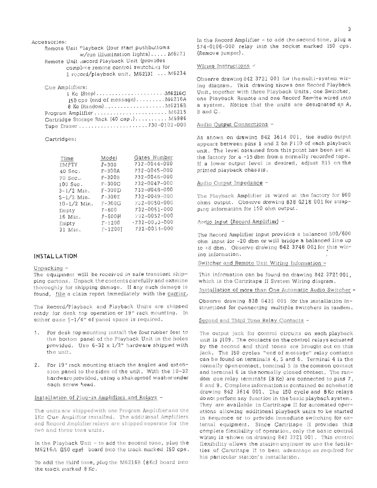
l.
Pres
sure
rol'
er
shaft.
2.
Soleno1d
plung
er.
3.
Toggle
Paw 1.
4.
Lifter
cam
surface.
The
pivot
nQia~s
should
be
l
ubric
a
ted
with
machine
oil.
REMOVAL
or
THE
TAP
E DECK
ASSEMBLY
If
it
should
be
com
e
necessary
to
remove
the
tape
de
ck
asse:l:bly
proce
ed
as
follows:
1.
T.00senthe
four
screws
on
TBIOI
and
take
off
the
wires.
Do
not
take
the
screws
a
ll
the
way
out.
When
pUlting
thes
e
wires
bac
k on
the
terminal
us
e
car
e to
matc
h up
th
e
wire
numbers.
'2.
Remove
Lie
fOI2:'
nuts
and
washers
which
secur
e
the
fronl
cas
ting
:')
the
\':
l~it.
Then
rO~dte
the
front
casting
un-
tH
it
c!Gars
l'H?
index
adJl~s[
~ever
and
la
y
it
beside
t
he
unit.
3.
RCr:1ove t'
le
five
machine
screw~
undcable
clamp
whIch
5
holds
the
tape
deck
to
the
main
chas
s
is.
4.
Remove
t
he
thre
e
sockel
head
cap
screws
which
hold
t
he
head
bra.ck
et
assembly
to
the
ta
pe
deck.
S.
Remove
the
two
machlne
scr
e
ws
holding
the
micro-
switch
[ 0
the
t
ape
deck.
Also
rem
ov
e t
he
screw
holding
I
he
tie
pOint
and
cabl
e
clamp.
6.
Slide
the
tape
deck
forward
and
out
of
the
unit,
CARE
0 F
TAPE
HEADS, CAPSTAN, AND PRESSURE ROLLER.
As
a
result
Of
th
e
lubricant
used
on
the
tape
proper
the
following
cleanJng
s
ch
edule
should
be
used
to
assure
con-
ti.:lUed
high
qua
lHy
reproduC
f
ion
.
1.
The
tape
heads
should
be
clea
ned
daily
to
5
everal
times
a
week
depending
on
the
service.
Wood
or'lsoprophyl
al-
cohol
may
be
us
ed
for
cleaning.
Place
a
cotton
swab
on
a
stick
long
enough
~o
insert
ir~
:he
cartridge
slot,
mOisten
and
ca
refu
lly
brosh
across
tr.c
heads.
2.
To
clean
the
c "
psta
n
and
pres
sure
roHer
the
tOp
cover
of
the
unit
must
be
remo
v
ed
.
The
lifter
cam
may
then
be
used
,0
raise
the
pressurerolier
u:':>ove
the
tape
deck
sur-
face
fc·r
easy
cleaning.
Refe
:'
lo
Fig.
1.
Us
e a
cotton
swab
moistened
with
wood
or
isoprophyl
alcohol
and
clean
the
ca
pstan
and
pressu!'~
roller
surfaces
.
Inspect
the
roller
f
or
free
turning
on
the
bearing
and
degrad
at
ion
of
t
he
rub-
ber
parts.
If
the
roller
1s
worr
or
defooned,
inadeql'at
e
pressure
wJllproduce
wow,
poorstar,ing
and
slow
speed.
R
eplace
with
Gates
parI
-'\730
-030
7
-000.
3.
Tape
heads
may
become
rrlagnc;~ized
by
l
ar
ge
unbal-
anced
pulses
through
th
e
record
te"d,
as
well
as
:[om
strong
magnetic
liclds.
Do
not
saturate
the
record
u:npli-
her
wi
'.
'1
abnonnally
high
inpul
signals.
Magnetized
heads
produce
excessively
high
noise
on
the
recorded
tape
ond
if
sever
e
enough
will
partially
erClse
them.
Thus,
;h<e
he
ads
should
be
demagn
etl
z
ed
weekly.
BE
LT
REP
LA
CEMENT
In
ord
er
to
repl
ac
e
the
drive
belts
the
top
and
bottom
cov
e
rs
at
lhe
un
it
must
be
removed
.
It
Is
jest
t:"1at
the
unit
is
set
on
its
side
to
per
form t
his
function.
I .
If
the
old
be
lt
s
are
to
be
removed,
take
them
off
of
the
flywh
ee
l.
At
this
poLnt a
stUf
piece
of
wire
with
a
small
hoo
k
on
one
end
is
very
useful.
Then
usIng
the
hook
on
the
wire
pu
ll
th
e
old
belts
up
through
the
pulley
cutolJt
trom
lh
e tOp.
2.
F
eed
the
new
b
elts,
one
at
"
time,
dow L
through
lhe
pull
ey
cutout
a
nd
place
them
around
the
pulley.
Use
the
wire
topull
tl're
belts
down
through
the
bottom
and
then
p
ia
ce
them
around
the
flywheel.
HEA
D
RE
PLACEI'v1
E
NT
1. To
replace
hea
ds
remove
th
e
pin
clips
from t
he
pins

(D
INDEX
SLIDE
ASS'y.
\
CARTRIDGE
HOLD
DOWN
SPRING
RIGHT
GUIDE
- "-
CARTRI
DGE
CLIP
CAPSTAN PRESSURE
~.
rr
~
e
ADJUSTMENT
"'-
LINKAGE
SLIDE
I
LIFTER
CAM
SURFACE
TOGGLE
PAWL
PIVOT
POINTS
"
PULLEY
CUTOUT
m
~
4
.,.,.
$1011111
1 -
.""~
.
oO~
\
.-
r rf
---
'
''~\f
Lt
ot
PRESSURE
ROLLER
INSERT
TIMING
ADJUSTMENT
, I
.'
"
,
~
~
~
..
;
~
fir
LIFTER
CAM
ASS'
y,
LIFTER
CAM
PROPER
<
~
.
r --
SOLENOID
PLUNGER
FIG. I
which
are
on
the
rear
of
the
heClds .
Make
a
note
of
the
w
ire
color
code
to
make
sure
they
are
reinstall
ed
correctly.
2.
Loosen
th
e
he
a d
cliJmp
and
remOVe
the
head.
After
the
new
head
is
insla
lJed
refer
to
Fig.
3
for
proper
placem
ent.
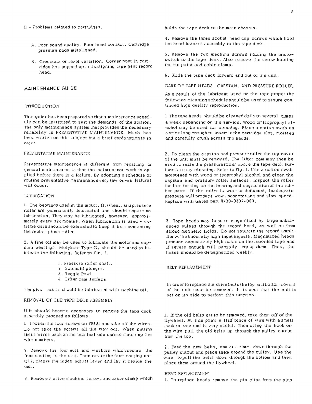
3.
For
th
e
final
adJustm
ent
of
the
heads
a
azimuth
tape
is
required.
The
Gates
73
2 0169
000
a
zimuth
tape
is
a-
vaiable
for
this
purpose.
Using
a
meter
to
read
the
out-
put
level
adjust
the
playback
head
for
maXlmum
output.
Record
a IS
KC
signal,
and
againread
the
output
level
of
the
playback
ampHfier,
and
a
dju
st
the
record
head
for
maximum
outpul.
Il
is
import
a
nt
that
the
playback
heod
azimuth
is
adjusted
first
and
then
record
head.
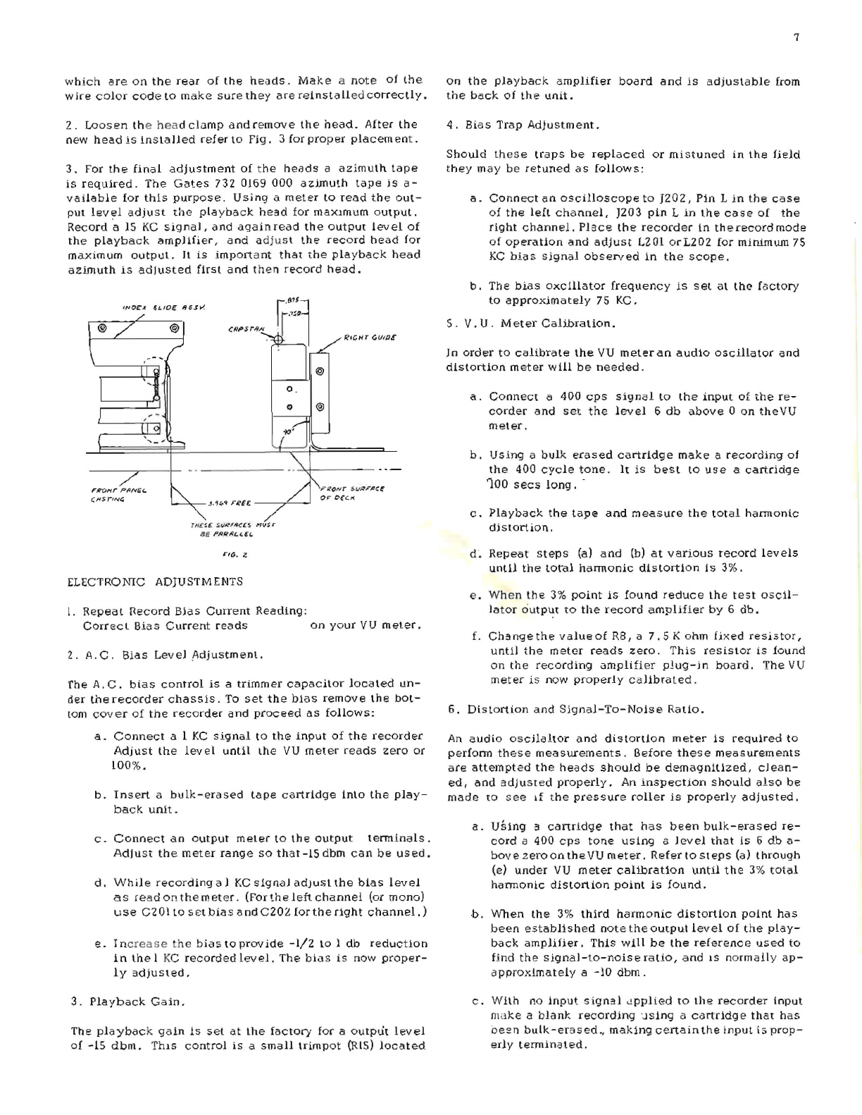
I,.,OCA
GLID£
IIG.s~
7
rroHr
PPNEc.
,
fl
Si/Nt:.
3_"'~~
Fet£
.,
r
r
tt
C
f.~
t.
f./RFIICl
·S M(JS r
8E
PR.lUl(..(.€c.
TfG.
it!
ELECTRONIC ADJUSTMENTS
l.
Repeat
necord
Bias
Current
Reading:
T?ICHT
Gf./ff].!'
I'
IlCIYT
5.r
JllFIIC~
o~
ceCl(
Correct
Bias
Current
reads
on
your
VU
meter.
2.
A.C
.
Bias
Level
I\djustment.
'fhe
A.
C.
bias
control
is
a
trimmer
capacitor
located
un-
d~r
the
recorder
chassIs.
To
set
the
blas
remove
the
bot-
tom
cover
of
the
recorder
and
proceed
as
follows:
a.
Connect
a 1
KC
signal
to
the
input
of
the
recorder
Adjust
the
level
until
the
VU
meter
reads
zero
or
100%.
b.
Insert
a
bu
lk-era
sed
tape
cartridge
into
the
play-
back
unIt.
c.
Connect
an
output
meter
to
the
output
tenninals.
Adjust
the
meter
range
so
that
-15
dbm
can
be
us
ed.
d.
While
recording
a I
KC
signal
adjuS;1
the
bias
level
as
read
on
the
meter.
(For
the
left
channel
(or
mono)
use
C'2
01
to
s
8t
bias
and
C20Z
for
the
right
channel.)
e.
In
crease
t
he
bias
to
provide
-1/2
to
1
db
reduction
in
the
1 KC
recorded
level.
The
bias
is
now
proper-
ly
adjusted.
3.
Playback
Gain.
The
playbac
k
gaIn
is
set
at
the
factory
for
a
output
level
of
-15
dbm.
T
hlS
control
is
a
small
trimpot
(R15)
located
7
on
the
playback
amplifier
board
anel
is
adjustable
irom
the
back
of
the
unit.
4.
Bias
Trap
AdJustment.
Should
these
traps
be
replaced
or
mi
stu
ned
in
the
field
they
may
be
retuned
as
fQ
11
ow
5:
a.
Connect
an
oscilloscope
to
J20
2,
Pin
L
in
the
case
of
the
left
channel,
J203
pin
L
in
the
co.
S8
of
the
right
channel.
Place
the
recorder
in
th
e
record
mode
of
operation
and
adjust
L201
orLZ02
for
minimum
75
KC
bias
signal
observed
1n
the
scope.
b.
The
bias
oxcillator
frequency
is
set
at
the
factory
to
approxim
a
tel
y 75 KC.
S.
V.
U.
Meter
Calibration.
In
order
to
calibrate
the
VU
meter
an
audio
oscillator
and
distortion
meter
will
be
needed.
a.
Connect
a
400
cps
signal
to
the
input
of
the
re-
corder
and
set
the
level
6
db
above
0
on
theVU
meter.
b.
USing
a
bulk
erased
cartridge
make
a
recording
of
the
400
cycle
tone.
It
is
best
to
use
a
cartridge
'100
sees
long.
-
c.
Playback
the
tape
and
measure
the
total
harmonic
distortion.
d.
Repeot
steps
(a)
and
(b)
at
variouS
record
levels
until
the
loral
hannonic
distortion
Is
3%.
e . When
the
3%
pOint
is
found
reduce
the
test
oscil-
lator
ciutP~t
to
the
record
amplifier
by
6
db.
f.
Changethe
value
of
RB, a
7.5
K
ohm
fixed
resistor,
until
the
m
etcr
reads
zero.
This
resistor
is
found
on
the
recording
(lmpli
fier
plug-in
board.
The
VU
meter
is
now
proper!
y c a
librated
.
6.
Distortion
and
Signal-To-Noise
Ratio.
An
audio
oscilaltor
and
di
stanion
meter
is
requlred
to
perfonn
these
measurements.
Before
these
measurements
are
attempted
the
heads
should
be
demagnit1zed,
clean-
ed,
and
adjusted
properly.
An
inspection
should
also
be
made
to
see
If
the
pressure
roller
is
properly
adjusted.
a.
USing
:I
cartridge
that
has
been
bulk-erased
re-
cord
a
400
cps
tone
using
a
level
that
is
6
db
a-
bovezeroontheVU
meter.
Refertosleps
(a)
through
(e)
under
VU
meter
calibration
until
the
3%
total
hannonic
distortion
paint
is
found.
h.
When
the
3%
third
harmonic
distortion
point
has
been
established
note
the
output
level
of
the
play-
back
amplifier.
This
will
be
the
reference
used
to
find
the
signal-to-noiseralio,
and
IS
normail
y
ap-
approximately
a
-10
dbm.
c.
With
no
input
signal
<..!pplied
to
the
recorder
Input
make
a
blank
recording
'..lsing a
cartridge
that
has
oe~Tl
bulk
-eras
ed.,
making
certain
the
input
i;;
prop-
erly
tenninated.

8
d.
Plu
yback
this
recording
and
measur~
the
noise
level
at
Lhe
output
of
the
playb"c;k
amplifier.
The
signal-
to-ratio
is
the
difference
between
th
e
noise
m
eas-
ured
and
the
relerenc
e
measured
ins
t
ep
(b).
This
should
be
a
-55
db
or
better
for
mono
or
-50
db
for
Stereo.
e.
With
the
steps
performed
above
reduce
the
input
LO
the
record
amplifier
6
db,
or
for a
readir."
of
0
on
the
VU
meter.
T
he
tot
al
harmonic
distortion
should
be
about
1%.
7.
Overall
Frequency
Response.
Before
an
attempt
is
made
to
make
an
overaH
frequency
response
lhe
following
should
br
done.
The
heads
should
be
demag:--tetized,
cleaned,
and
properly
adjusted.
The
A.
C.
bIas
should
be
check
ed
for
this
has
an
uff~ct
on
re-
spons
e
if
misadjusted.
Refer
to
A.
C.
biOI
s
level
adjUE~
m
ent
for
this.
a.
Connect
an
audio
oscilla~or~:)
the
input
of
the
re-
cord
amplifier
and
set
:he
record
level
[or
a -10 db
as
read
on
~he
VU
meter.
b.
Using
a
cartridge
that
has
been
buL,,-erased
make
a
recording
u6ing
400
cycles
as
the
reference
tone.
Then
record
a
short
series
of
frequencies
irom 50
cps
to
21
KC, mflking
sure
that
the
input
signal
is
held
CIt a
const,--ut
leveJ.
Playback
the
tape
and
note
th
e rea
dings.
The
reSpons
e
should
be
approxI-
mately
±.
3
db.
Factors
Which
Affect
Frequency
Response
-
1.
Head
height
and
head
pos
ilioning.
Reier
to
Fig.
3.
2.
Azimith.
3.
Worn
tape.
4.
Pressure
pads
-
as
pad
pressure
is
increased
the
'1igh
frequency
output
will
incr
ea
se
unlil
th
e pOint
1s fc,-'ched
where
it
wil
l
level
out .
Excessive
pad
pressure
will
cause
wear
to
the
heads
as
well
as
to
the
tape.
C/i
RTRIt
>C£
,rC6£
-
"-----
--
(,O:~rN4
~~P£w
TIIP~
Ne
RD
I'.CI'f£rR~TI{)1V
c
p~rR/D6~
STO~
;?
OJVSTIN6
Sc~Fw
(,II!;rR/06~
!;il'J;O
dh'1
= .
,,
~:s=t!OLib
000 /
..
,x
I I
R(-:C~D
PLiW
e RCK
It'E~"
If~R"
FIG
, .3
5.
A
large
accumula.tion
of
oxide
on
the
heads
will
re-
duce
high
frequency
output.
This
has
the
affect
of
holding
the
~ape
away
from
the
heads.
8.
Voltage
Measurements.
Refer
to
the
voltages
shown
on
the
schematic
diagrams.
Usc
a 20,QOO
ohms
per
voltmeter.
MECHANICAL
AOfLISTMENTS
These
adjustments
are
carefully
made
at
the
factory,
how-
ever,
a
periodic
checking
is
required
to
keep
the
unit
in
peak
operating
condition.
ThIs
information
is
listed
below
(check
every
6
months).
IMPORTANT -The
following
adjustments
are
described
in
the
correct
sequence
of
adjustm
ent.
Right
Guide
Position
Observe
Fig.
2 for
details.
The
right
guide
should
be
sql:clfe
to
the
front
of
the
deck,
and
.875
inches
from
the
center
of
the
capstan
to
the
working
edge.
Index
Slide
Assembly
Observe
Fig
..
2 for
details.
This
assembly
should
be
po-
sitIoned
parallel
to
the
right
guide
and
adjusted
so
that
the
rubber
rollers
compress
a
~ull
1/32"
when
a
cartridge
is
inserted.
Try
several
cartridges
as
they
vary
sam
ewhat.
Cartridge
Stop
Ob,serve
Flg.
3 for
details.
This
stop
prevents
the
cap-
stan
from
rubbing
on
til e
cartridge.
Adjust
th
c
stop
to
pro-
vid
e
1/32"
of
clealdnce
between
the
capsta
n
dnd
the
car-
tri
dg
e.
Try a
number
of
cartridges
as
they
vary
sligh.ly.
Head
Penetr:>Uon
Th
is
should
be
checked
every
six
months
or
whenever
the
heads
are
replaced.
Obs
(;cv
e
FiJ.
3 for
details.
Pos
iUon
the
tape
head
in
the
head
br,'c:':et
so
that
it
penetrates
the
cartridge
9/32"
.
Head
Heighl
ThiS
should
be
checked
ev
ery 6
month
s
or
wh
e
never
the
heads
are
replaced.
Obs
erve
Fig . 3 f
or
details.
Adjust
the
h
,~ad
height
by
adjusting
th
e
two
s et
screw
s
front
and
rear.
The
correct
hei.ld
height
is
.562
inch,
:I:
.002
inch
I
to
the
top
of
the
upper
head
piece.
It
is
important
that
the
front
edgfC
cJf
the
head
be
square
with
the
deck
surface.
Lift
er
Cam Pos
iHan
Observ
e
Fig.
4 for
de
tails.
The
lifter
cam
s
hould
be
po-
sitioned
so
there
1s
.020
inch,
::!:..005
inch,
clearanc
e
be-
tween
~he
roller
lever
and
th
e
li
fter
cam.
The
shaft
of
Lhe
ass
embly
should
be
pa
rallel
to
the
rear
of
the
dec
k .
Cartridge
In
sert
Ti
min
g
(Pressur
e
Roller
Adji,::;tment)
Th
is
adjustm
ent
should
be
checked
every
month.
Obs
erve
Flg.
4 for
details.
Adjust
thc
pas
ition
of
the
nylon
cap
by
turning
the
soc
ke
t
he
ad
cap
scr
ew .
Ins
ert
a
cartridge
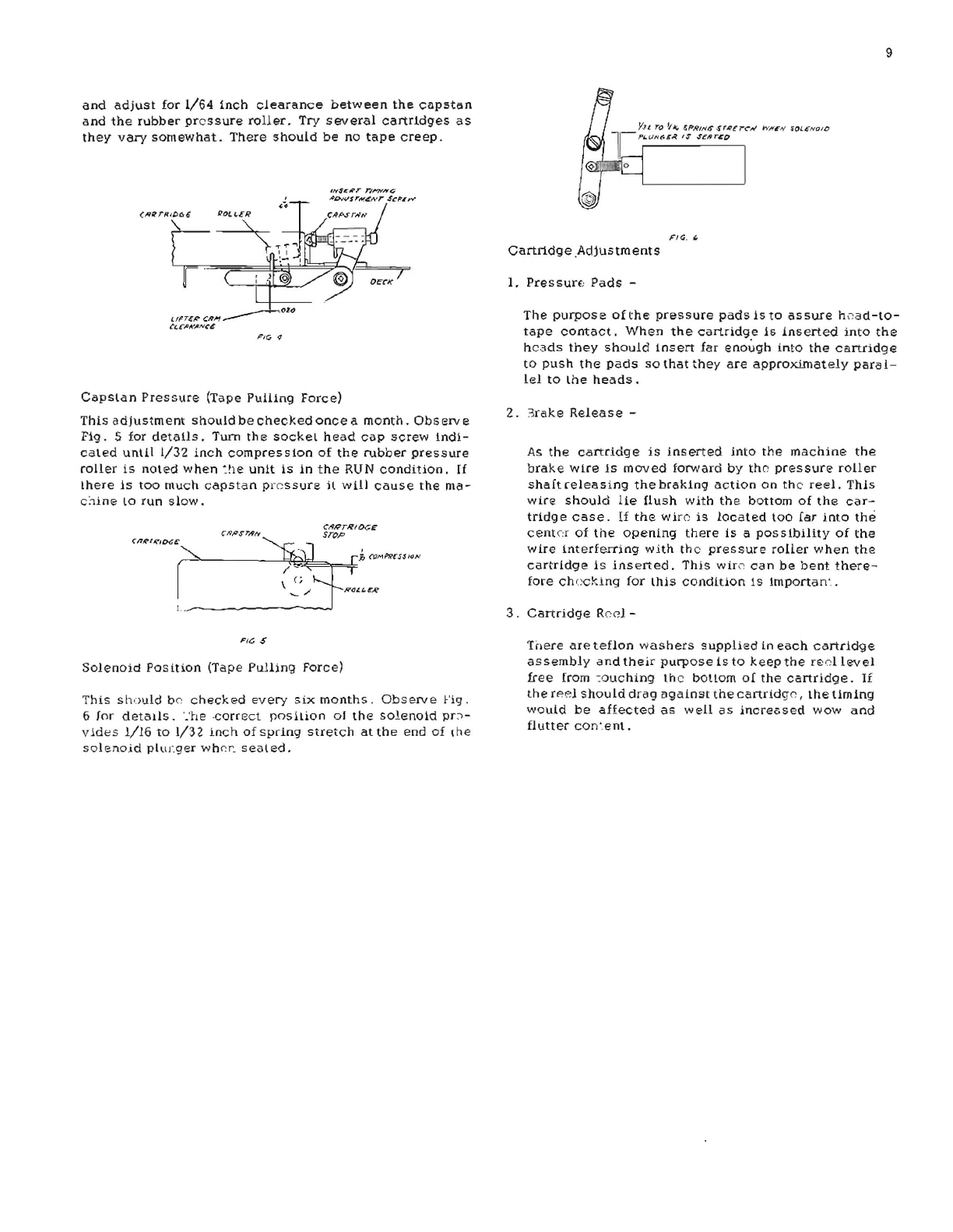
and
adjust
for
1/64
inch
clearance
between
the
capstCin
and
the
rubber
pressure
roller.
Try
several
cartridges
as
they
vary
somewhat.
There
should
be
no
tape
creep,
LfrT£P'
CA,.,
Ct:,C,RKIIN~e
O't)
FIG
(/
lI"seNT
rtI'WNt:;
'#DNsrM4Nr
SCfI'r"..,.
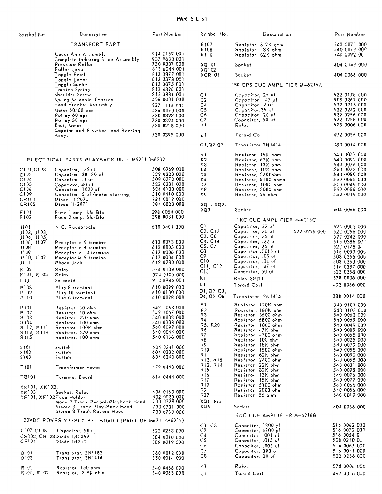
CopSlan
Pressure
(Tape
Pulling
Force)
This
adjustment
should
be
checked
once
a
month.
Obs
erv e
Fig.
5
for
details,
Tum
the
sockel
head
cap
screW
Indi-
cated
unll.l
1/32
inch
compression
of
the
rubber
pressure
roller
is
noted
when
~he
unit
Is
in
the
RUN
condition.
If
there
is
too
much
capstan
pressure
it
will
cause
the
ma-
C:"1ine
lO
run
slow.
C/1~t~ID(;£
CI9;O$7"'1P1Y
Ct9J'i'rlltOGE
""'-.
~"
STOP
:
~~
Fi~-"
..
\~./
~Ra"
...
",
----~
FfC,
S
Solenoid
Pos
iti.on
(Tape
Pulling
Force)
This
should
be
checked
every
Six
months,
Observe
fig
,
6
for
details.
'
.'he
-correct
position
01
the
solenoid
pr:->-
v.ides
1/16
to
1/32
inch
of
spring
stretch
at
the
end
of
\he
solenoid
plllJ
~
ger
wh('r.
sealed.
Yn
ra
"
....
G.~R/~&
.s"~~"",~""
n 'ItE'.o,I
~OLIiNQIO
pl..r.JN(.r;(
IS
S~lfrCD
PIG_ "
Cartridge
,Adjustments
I.
Pressurf;
Pads
-
9
The
purpos
e
of
the
pressure
pads
is
to
as
sure
h;;ad-to-
tape
contact.
When
the
cartridge
is
inserted
into
the
heads
they
should
insert
far
enough
into
the
cartridge
to
push
the
pads
so
that
they
are
approximately
paral-
lel
to
the
heads.
2.
3rake
Release
-
As
the
cartridge
is
ins
erted
into
the
machine
the
brake
wire
1s
moved
forward
by
tho
pressure
roller
shaft
relea
sing
the
braking
action
on
the
reel.
This
wire
should
lie
Hush
with
the
bottom
of
the
car-
tridg
e
case,
If
the
win;
is
located
too
far
into
the
cent,:r
of
the
opening
there
15
a
possibility
of
the
wire
Interferring
with
the
pressure
roller
when
the
cartridge
is
inserted.
This
wir;;
can
be
bent
there-
fore
ch()cking
for
lhis
condition
Is
Importan'
"
3,
Cartridge
Re,d
-
Trlere
are
teflon
washers
supplied
in
each
cartridge
assembly
and
their
purpose
is
to
keep
the
reollevel
free
from
~ouching
lh
c bOllom
of
the
cartridge.
Ii
the
r~eJ
should
drag
against
the
cartridg(),
the
timing
would
be
affected
as
well
as
increosed
wow
and
flutter
con'ent.
PARTS
LIST
Symbol
No,
Descri
pt
ion
TRANSPORT
PART
Leve,
Arm A&
semb
Iy
Comple
Ie
Index
ong
SI
ide
A.
~emb
Iy
Pres
s
'"c
Roller
Rolle'
leve'
Tosgle
Powl
T
osgle
Leve,
T
ogg
10
Soc
kct
T
",s
ion
Sp'
ing
Shou
Ide r Screw
Sf"
ing
So
lene>id
Te
ns,
on
Heod
-B"rocket
Ass
emb
Iy
Moto,
50/60
cps
Pulloy
60
cp~
Pulley
50
cps
B.,It,
Motor
Co
ps
Ion
and
F
Iywhee
I
ond
Beor;ng
Assy.
PorI
Nvmber
91J
2159
001
937
9630
001
730
0307 000
8136244001
813
3877
DOl
8133878
DOl
8133875001
8134326001
8133881
001
456
0001 000
927
1116 001
436
OO~O
000
730
0393
000
7300394
000
730
0228
000
730
0395
000
ELECTRICAL
PARTS
PlA
YBACK
UNIT
M621l/M6212
Cl
01,C
1
03
Cl02
Cl04
Cl05
Cl06
CI09
CRIOI
CR105
F101
Fl02
Jl01
J102,
JI03,
JI04,
Jl05,
Jl06,
Jl07
J 108
jl09
J110,
jl07
Jill
KI
02
Kl01,
/(103
LIOI
Ploa
PI09
PIlO
RIOI
Rl02
RI03
Rl0d
R112,
Rill
R113,
RIl<l
RI15
5101
S102
5103
nOI
T8101
Capac
ito',
.25 vI
C
opoe
ito',
30-
30 vi
Capac;lo"
.1
vi
Copoc
iIO(,
40
vi
Copodlo"
\
000
vI
Co
pocilo"
5
uf
(mo!
or
510rl
;ng)
Diode
IN2070
D;od~
lN2071
Fuse
1
omp.
Slo·8lo
Fuse
20mI',
Slo·810
A,C.
Rcceplocl"
Rec
"proc
Ie 6
lermino
I
Rec"prac
Ie 8
lermi
no I
Rece
ptoc
Ie 10
lermina
I
Reeept"e
Ie 6
I"rmina
I
Phone
Jack
Relay
Relay
5,,1
enu;
d
Plug
8
!"rmina
I
Plug
10
lerminol
Plug
6Ie,min,,1
Resisto"
30
ohm
Res
,slor,
50
ohm
Res
iSlof,
220
ohm
Res
i
.10',
100 ohm
Res'
SIor,
lOOK
ohm
Res
istor,
620
ohm
Res
i
s~o"
100 ohm
Switch
Switch
Switch
Tronsforme,
Power
Term;nol
Board
XK101,
XKI02,
XK 103
Socket,
Re
loy
XF101,
XF102Fv5e
Holde,
Mono
2
Track
Record-Playback
Heod
Slereo
3
Track
Ploy-Bock
Head
Stereo
3 T
rock
Record
Head
508
0269000
522
0320
000
508
0270
000
522
0301 000
524
0100
000
5JO
0410
000
384
0019
000
384 0020 000
398
0054
000
398
0081
000
6100<101 000
6120373000
612
0005
000
6120006000
612
000<1
000
6120280000
5740108000
574
0106
000
9138946001
6100099000
6100100000
6100098
000
542
1068 000
542
1067000
540
0033
000
540
0308
000
5<10
0097
000
540
0044000
5400166
000
604
0241
000
604
0232
000
604
0240
000
472
0443 000
6140444000
404
0160000
4020023
000
730
0729
000
730
Q731
000
7300730
000
30VDC
POWER
SUPPL
Y
p,c.
BOARD
(PART
OF
M62111M6212)
C107,Cl08
Copo<i'or,
59
tlf
CRI02,
CR103D,ode
lN2069
CR104
Diode
lN710
QIOI
Trons;,lor,2NI183
0102
Trar"i~l"r,
2N1414
Rl0S
Resistor,
150
ohm
R
l06,
R 109
Re5lslor,
3 9K
ohm
522
0258
000
3840018000
386 0019 000
3800012000
380
0014
000
5400458
000
540
0063
000
Symbol No.
Rl07
RI08
R110
XQIOI
XQ102,
XCRI04
Cl
C2
C4
C5
C6
C7
Kl
Ll
Ql,Q2,Q3
RI
R2
R3
R~
R5
R6
R7
RB
R9
XQ1,
XQ2,
XQ3
C1
C2,
C15
C3, C6
C4,
CI4
C5,
C7
C8
C9
CIO
Cll,
C12
C13
Kl
II
Ql,
Q2,
03,
04,05,Q6
Rl
R2
R3
R4
R5, R20
R6
R7
RS
R9
RIO
Rl1
R12, RIB
R13, R
14
RI5
R16
R17
R19
R21
R22
XQl
In,u
XQ6
CI,
C3
C2
C4
C5
C6
C7
C8
K1
11
Oeser
ipl
ion
Res
isto"
8.2
K ohm
Resistor,
18K
ohm
Res
i
stor,
62K
ohm
Socket
Sock"t
150
CPS
CUE
AMPLIFIER
M-6216A
Copoc;lor,
25
vf
Copocitor,
.47 vf
Copacitor,
2
',If
Copoeitor,25
vI
Copacitor,
20
vi
C"pocitor,
50
ul
R,,1ay
Toroid
Coi
I
Trons;sto,2NI414
Res
istor,
15 K ohm
Res
os
lor,
621<
ohm
Resistor,
13K
e>hm
Res
;stor,
10K
ohm
Resistor,
27000hm
Res
islor,
5100
ohms
Res
istor,
1000
ohm
Res
iSlo(,
2000
ohm
Res;
5tO',
56
ohm
Socket
lKC
CUE
AMPLIFIER
M-6216C
Copocito(,
22
vi
Copac
itof,
20
vi
Capae,tcc,
25
uf
Copoc
itor,
.22
uf
Copoc
itor,
25
uf
Copoe,lor
,0015
vi
Co
poc
,10',
.05
uf
Co
pac
i
fOr,
.04 vI
Capoci~o"
.47
vI
Capacito"
50
vi
Reloy
SPDT
Toroid
Coil
T'onsistor,2NI414
Resislor,
150K ohm
ResisTo"
1801< ohm
Res;stor,
3600
ohm
R""istOf,
6800
ohm
Resislor,
1000
ohm
Resislor,
<17K
ohm
Resistor,
4700
.o,m
Resistor,
100
ohm
Resistor,
18K
ohm
Res
i
5to"
1800
ohm
Res,stor,
62K
ohm
Res'slor,
2400
ohm
Re~,
~ro"
22 K ohm
R",.istor,
82K
ohm
Resistor,
13K
ohm
Resi.!or,
15K
ohm
Resi.lor,
5100
ohm
Res
islor,
2000
ohm
Res
is
'or,
56
ohm
Sockel
522
0256 000
8KC
CUE
AMPLIFIER
M-0216B
COpOCil"'<
1800
pf
Co
poe
ilo"
4700
pi
Capacitor,
.001 vi
C"pocilor,
.015
vi
C
opoc
ilor,
.003
vi
Co
poe
,lor,
390
pI
Capcc,ior,
20
vI
Relay
To,oid
Coil
PorI
Numbe,
540
0071
000
540
0079
DOl'
540
0092
OC
404
0149
000
404
0066
000
5220178
000
5080267
000
522
0215000
522
0242
000
522
0256
000
522
0258
000
578
0006
000
492
0056
000
3800014
000
540
0077
000
540
0092
000
540
0076
000
540
0073
000
5400059000
5400066
000
5400049
000
5400056
000
5400019000
404
0066
000
526
0002
000
522
0256
000
522
0242
000
516
0386
O('~
522
0178
O·
516
0059001./
508
0266
000
508
0253
000
516038700(1
522
0258
000
578
0006
000
492 0056
000
380
(l014
000
5400101
000
540
0103
000
5400062
000
5400069
000
5<10
0049
000
5400089
000
5400065
OliO
540
0025
000
5400079
000
540
0055
000
5400092
000
540
0058
000
540
0081
000
540
0095
000
540
0076
000
5400077
000
540
0066
000
540
0056
000
5400019
000
404
0066000
5160062000
5160072
00(1
516
00540
508021001-
5160067
000
5160041
000
522
0256
000
5780006
000
492
0056
000
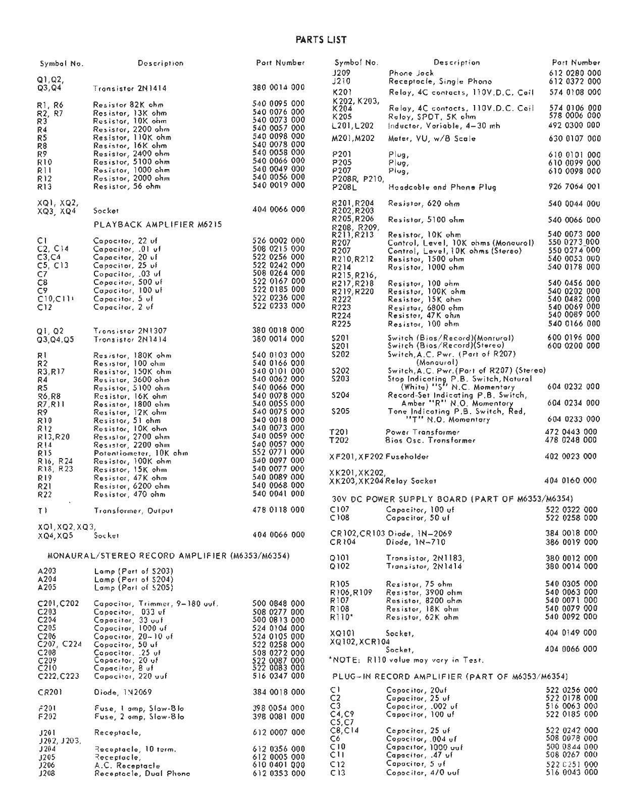
PARTS
LIST
Symbol No.
Ql,Q2,
Q3,Q4
Rl,
R6
R2,
R7
R3
R4
R5
R8
R9
RIO
RII
R12
R13
XQI,
XQ2,
XQ3,
XQ4
Cl
C2,
C14
C3,e4
C5, C13
C7
CS
C9
Cl0,Cll'
C12
OJ,
02
Q3,04,Q5
Rl
R2
R3,R17
R4
RS
)<16,R8
R7,RJ 1
R9
RIO
RI2
R13,R20
RI4
RlS
R16,
R24
R18, R23
RI9
R21
R22
TJ
XQI,XQ2,XQ
XQ4,
XQ5
Doscripli<>n
Tronsislor
2N1414
Res
;stor
82
K ohm
Res
istor,
13K
ohm
Resistor,
10K ohm
Resistor,
2200
ohm
Resistor,
IIOK ohm
Resistor,
16K
ohm
Resistor,
2400
ohm
Resisto"
5100
ohm
R""'stor,
1000
ohm
Res.istor,
2000
ohm
Res
ilitor,
56
ohm
Socket
PLAYBACK
AMPLIFIER
M6215
Copoc.lo(,
22
u1
Capacitor,
.01
vI
C"pocitor,
ul
Co
l'oeil
or, ul
Copo,ilor,
.03,,1
Copoc
;tor,
500
vI
Copoe
ilor,
100
vI
Copocitor,
!i
vi
Capacitor,
2
vf
TronsiSlor
2NJ307
TrO",;510{
2NU14
Resistor,
IBOK
ohm
Res.slor,
100
ohm
Resistor,
150K ohm
Res
is'
or,
3600
ohm
Resis.lor,
5100
ohm
Resistor,
16K ohm
Res
islof,
1800
ohm
Resistor,
ohm
ResistQr,
I ohm
Res
is
lor
• I
ohm
Res.slor,
ohm
ReSlslor,
ohm
Potentiometer,
10K
oh
....
Res
j
slor,
lOOK
ohm
Resistor,
15K
ohm
Resistor,
ohm
Resistor,
ohm
Resistor,
ohm
Transh:>rfflIH,O!.llpVI
kef
Potl
Nvmber
380
0014
000
.540
0095
000
540
0076
000
5400073
000
5400057
000
0098000
0078000
0058000
0066
000
0049
000
0056000
0019000
404
0066000
0002
000
0215
000
0256
000
0242
000
0264
000
0167
000
0185
000
0236
000
0233 000
3800018
QOO
360
001.4
000
0103000
0166
000
0101
000
0062
000
0066
000
0078000
0055000
0075000
0018000
0073
000
0059 000
0057
000
0771
000
5400097000
5400077
000
0089
000
0068000
0041
000
47B
0118
000
404 0066 000
MONAURA
Ll5TEREO
RECORD
AMPLIF
IER
(M6353/M6354)
A20J
A2Q4
A20S
C201
C203
C2ll4
C205
C206
007,
C224
C208
C209
C210
C222,C223
CR201
no.
F202
J201
n(\2,
n03,
)204
J205
)206
J20$
Lamp
Lamp
Lomp
of
5203)
01
5204)
of
5205)
Copoeilor,
Trimm,,,,
9-180
<.Iv!'
Copoe;I"",
033
vi
Copac;!"r,
33
"vi
iTor,
1000
vi
itor,
20-10
"f
iIO',
50
vi
poe
itor,
vi
pac",o"
vi
Co
pac
iter,
8 vI
Co
padtor,
no
uuf
Diode,
1
~2069
fvr-e,
•
amp,
Slow-51"
fvse,
2
omp,
:,low-8Io
Reeeptoc
Ie,
5000848
000
000
000
000
000
000
000
000
000
516
000
3840018
000
3980054
000
398
0081
000
6120007
000
000
000
000
6120353
000
Symbol
No.
J209
Description
j210
Receptocle,
Single
Phono
K201
Reloy,
4C
contacts,
nOV.D.C.
C01l
K202,
K203,
K204
Re loy, 4C
conTacts,
11
OV.
D.
C.
Coj
I
K205
Reloy,
SPOT,
5K ohm
L20
I,
L202
I
nd
\Jclo"
Voriob
Ie,
4-
30
mh
M201,M202
Meter,
VU,
w/8
Scale
P201
Plug,
P205
Plug,
P207
Plug,
P208R,
P210,
P20SL
HoadcQblOi'
and
Phone
Plug
R201,R204
R202,R203
R205,R206
R20B,
R209,
R211,R213
R207
R207
R210,R212
R214
R21 5,
R216,
R217,R21B
R219,R220
R222
R223
R224
R225
5201
5201
S202
5202
5203
5204
5205
Resistor,
620
ohm
Resistor,
5100
ohm
10K
ohm
evel,
10K
ohm!>
(Mooou,ol)
Level,
10K
ohms
(Stereo)
;slo.,
1500
ohm
Rosistor,
1000
ohm
Res
Slor,
100
ohm
Res
slo.,
lOOK
ohm
Res
slor,
15K
ohm
slor,
6800
ohm
slor,
471<
ohm
Resistor,
100
ohm
T201
Power
T
(onsformer
T202
8ios
Osc.
Transforme,
X
F201,
XF202 F
vseho
Ider
XK201,
XK203,X
Soeke,
JOV DC POWER
SUPPLY
BOARD
(PART
OF
Cl07
Copacitor,
100
vi
Cl08
501.11
CR102,CR103
Diode,
IN-2069
CR104
Diode,lN-710
Ql01
Ql02
Rl0S
R106,R109
Rl07
RIOa
Rl10*
XQIOl
XQ102,
Transistor,2NI183,
T.ans
istor,
2N1414
Resistor,
75
ohm
s
isto(
(
3900
ohm
$
islol,
8200
ohm
Resis!or,
18K ohm
Resistor,
621<
ohm
Sockel,
'NOTE:
RllO
volue
moy
vory
in
Test.
Port
Number
612 000
612 000
5740108000
0106
000
0006
000
492
0300
DOD
6300107
000
6100101
000
6100099000
6100098
000
926
7064
001
5400044
OOU
5400066
000
0073
000
0273 000
027'(000
0053
000
0178 000
0456
000
0202
000
0482
000
0069
000
0089 000
5400166
000
6000196
000
6000200000
604
0232
000
604
0234
000
604 0233
000
0443000
0248000
4020023000
404
0160000
000
000
384 0018 000
386
0019
000
380
0012
000
3800014
000
540
0305
000
0063
000
0071 000
0079000
0092000
404
0149 000
404
0066000
PLUG-IN
RECORD
AMPLIFIER
(PART
OF
M63531M6354)
C J
Copo~
ilor,
20u/
0256
000
C2
ilor,
25
ul
0178
000
C3
.002 uf
0063
000
C4,C9
1001.11
0185
000
C5,C7
C8,C14
C6
CIO
ClI
C12
C13
25
vf
_004
vr
1000
vul
.47
ul
Copocitor,
5
vf
Copoe
""r,
410
uuf

PARTS
LIST
Symbol No .
Ql,Q2
Q3,Q4
Q5
Rl
R2,
RI2,
R17
R3
R4,R6,R21
R5,"R16,R25
R7
R8
R9
RIO
Rl1,R15
R13
R14
R18,R26
RI9
R20,R24
R22
R23
TI
XQ1,XQ2,
XQ3,XQ4,
XQ5
Descrtption
T
ron5;S
tor,
2N 1307
Tronsistor,2Nl414
Res
i
stor
,
16K
ohm
Res
istor,
3600
ohm
Res
istor,
20}( ohm
Resislor,
5100
ohm
Resistor
,
10K
ohm
Res
i
stor,
6200
ohm
Res
islor,
7500
ohm
Resistor,
430
ohm
Resistor
,
2200
ohm
Resistor,
51K
ohm
Res
islor
,
3900
ohm
Resistor
,
680
ohm
Res
;
slor,
820
ohm
Res
istor,
2000
ohm
Resislor,
47K
ohm
Resislor,
110K ohm
Resistor,
200K
ohm
Input
Transformer
Sockel
PorI
Number
3800018000
380
0014
000
5400078000
5400062
000
5400080
000
5400066000
5400073
000
5400068000
540
0070000
5400040000
5400057000
5400090000
540
0063
000
5400045
000
540
0047
000
5400056
000
5400089
000
540
009.8
000
5400104
000
4780118000
404
0066
000
CAPACITOR
BOARD
(PART
OF
M6353
/M6354)
e211
C212
,
C213
C220
C214
C215
C216
,
C218
C217,
C219,C221
Copocitor,
3.9
1.11
Capacitor
, .68
ul
Copoeitor,
.0471.11
Copocitor,
.004
vi
Copocitor
,
.005
vI
COp"c;lor,
.015
uf
Copoc
ilor,
.1
1.11
526
0003000
50a
0164000
50a
0267
000
508
0276
000
5080076000
508
0210
000
SOB
0278
000
PLUG-IN
BIAS & 3
TONE
OSCILLATOR
(PART
OF
M6353
/
M6354)
Cl,C2
C3,C4
C5
C6,C9,Cll
C7
C8,e12
Ql,Q2,
Q3,Q4,Q5
Rl,R2
R3,R4
R5
R6
R7
R8,R9
RIO
Rl1
R12
R13
R14
R15
R16
R17
R18
R19
R20
XQ1,XQ2
,
Ca
pac
ito" .47
1.11
Capacitor,
.01
1.11
CapaciTor,
20
ul
Co
poc
itor
,
25
uf
Capacitor
, 2 vI
Copocilo
r,
25
uf
Tron.istor
,
2NI414
Re,;stor,
10
ohm
Resi,!or,
22K
ohm
Resistor,
510
ohm
Resistor
,
3600
ohm
Resistor
, 12
00
ohm
Res
is
tor,
1500
ohm
Resislor,
1300
ohm
Resistor,
200
ohm
Potontiometer,
10K
ohm
Resistor,
43K
ohm
Res
is
tor,
13K
ohm
Resistor,
2200
ohm
Resis!or,
47K
ohm
Resistor,
1800
ohm
Resistor,
7500
ohm
Res
is
tor
,
430
ohm
Resistor
,
300
ohm
XQ3, XQ4, XQS
Socket
MONAURAL
SWITCHER
M-6219
C301
Capocitor
,
40
vI
CR301 Di
o<le
1
N2070
CR302
!hru
CR309
Diod
e
IN2071
508
0267
000
506
0001
000
522
0256
000
522
0242000
522
0169
000
522
0178
000
380
0014
000
540
0154
000
5400194000
540
0042
000
540
0062
000
5400051
000
540
0053
000
540
0052
000
540
0032
000
552
0771
000
5400088000
5400076
000
540
0057
000
5400089000
5400055
000
5400070
000
540
0040000
5400036
000
40tl
0066
000
522
0315000
384
0019
000
384
0020
000
Symbol
No .
Description
F301,F302
Fuse,
lamp.
J301
A. C.
Rcceploci
e
J302
Reee
ptocla
J303,n04
Rece"toc
Ie
K301
L,
K302L
,
K303
L, K304 L Re loy
P302
PllIg
P303
PllIg
R301
Rosislor
,
100
ohm
R302
Resistor,
Adj,
41<
ohm
R304
,
R306,
R308
,
R310
,
R312,R314,
R316,R318
Res
istor
,
7500
ohm
R319,R320
Resislor,
620
ohm
R321
, R322
Resistor,
10K ohm
5301
Switch
X
F301,
X
F302
Fuseholder
XK301 L/ R,
XK302L1R
,
XK303L
/ R,
XK304L
/ R
Socket,
Relay
S501
5502,
S504
S503
S505
S401
S402
5403
5404
5405
REMOTE
RECORD
UNIT
M6234
Sw
teh
Sw
teh
Sw
tch
Sw leh
REMOTE
PLAYBACK
UNIT
M6221
Swilch
Switch
Switch
Switch
Swi
tch
Pori
Number
398
0017
000
610
0401
OC
612
0007
OOll
6120009000
574
0106
000
610
0101
000
6100103000
5400587
000
5520031
000
540
0353
000
540
0044
000
540
0073
000
604
0244
000
402
0023
000
404
0160
000
604
0240
000
604
0232
000
604
0234
000
604
0233
000
604
0235
000
604
0236
DO'
·
604
0237
000
604
0238 000
604
0239
000

r - -
-,
r -
-,
: 0:
I ®:
I
,
~
I
~
I
~
,~
I
I
,.
-
-,
:0 :
:
61
I
:@
I
:®
~
:
:
0~
·
:
er)
:
,
,
~
' 0
,
~
:@ I
~I
:@
~
~ ~:
:@:
~~
L .
:@.
~~
t
__
J
t-.J
~
;
:~
'"
~
r
----,
:0
:
:@
I
:@
:
:~~:
,,,",,
:~
ro:
:
&l
I
:®
r--
--,
- ,
P}:4
r
.!
I
~P
5'
a1
..,f
~1):
~
Y
~
..j~'
'
.;.,
....
1
I
~
I
:
®
~I
:0
:® I
L _ •
~
r - - i
0:
®;
I*~
} -.J
~
r - - ,
:0
Q
'@
,8
~
:'
@~
I
:
El":
:e
,@
,e
,®
c
--'
-,
r -
~~
-
....,
80
:
®®;
"@(9
,
:~~
@
~
, '
@@:
@€l:
l
__
. •
.<
~
t:
r -
h~
~
,I
~ ~
I
~~:
:...
~'I
b
.....
~
~:~
I
~~:~(0:
~g,
'
OJ
"
<..
. , -
~~
"'\
~
,
''>
~,
:i)
,':;~
v~
" "
;:.~
0,
~~
~
;
i
"
"
'-
e.S(J(
3
-:'
~.f.::oJ-"I_
YQ~f;N·.
T
I!-s~~
,
'!'£t~~I-~
..
~"",-;z-
~?e""3
-("
~
~:>j'
- /
iJ$".c>Z-{
7
",Q~-i!
.
I~
J.:
..
I~
~
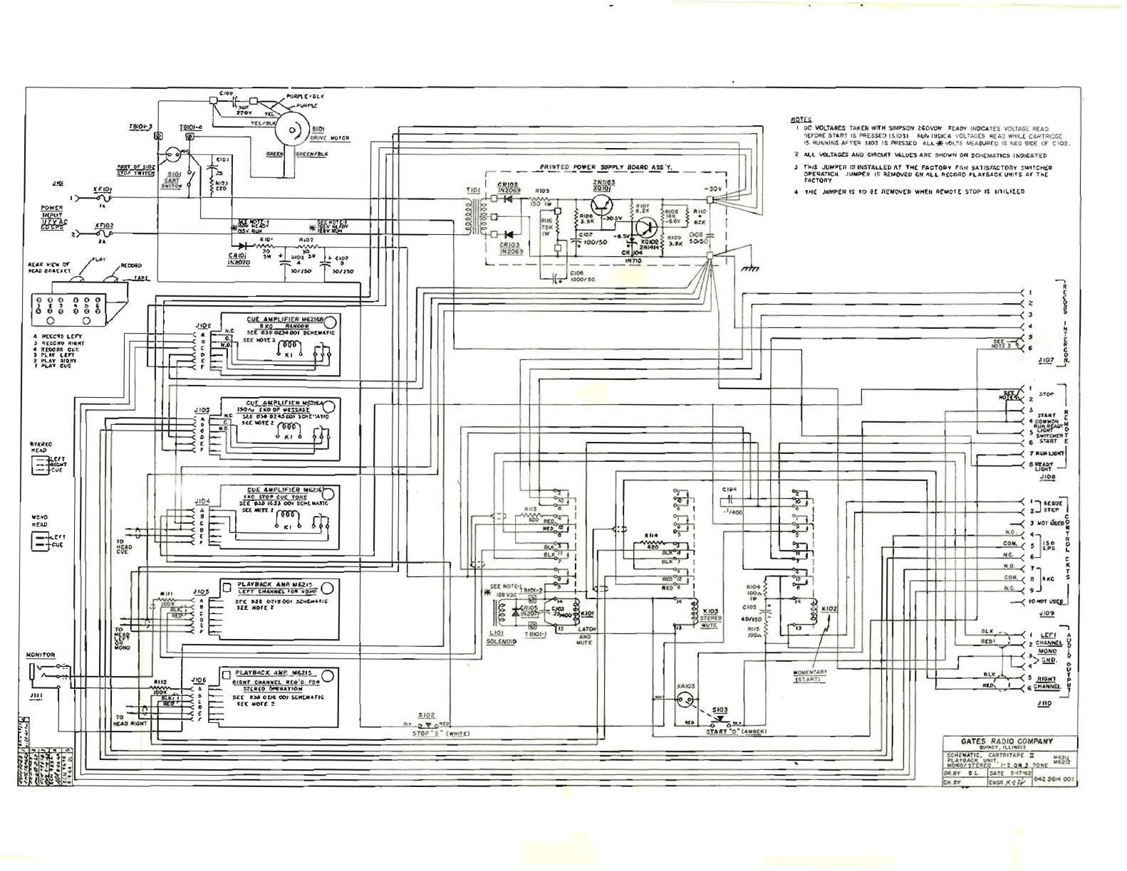
L'f/l
I'OW!R
~C
4 I'O;C_O u :
n-
, 'I[(:CIIO
RHIN1
,.
ftlWlUI
C:~F.
,
PL.
...'
Lc:n
Z
PUY"
IUQIn
II
#lUI"
C:u~
~
-<tV
"
1r"30l
~
fA
,!!!.O!::,
U.t2!:.!
~
J-'2.'
, .
,
<
.
,
t
r
""--
-
-!R!!!.!
£!...
PO.!I.R...!2p~a~ItC~
·
L
-
--,
~
I
~
_"
"I
~!~J
*1#!!i..1'ik
4f-..:
01
f'CI'
'''07
~o
~-l'-,-,,-~-,--tI-~I~I.lI.JI-
1
Tso'".o T
)olIto
=
I
oe
VOLTAO£5
TA
IC
,
EN
wlt'H
SIt(PSC
)t
loG
O
vow
1;[~[7Y
l
UO
IC&
l
(S
~
,
~
(
FlUO
~tr
Cil:
(
s U.l'rr IS PRES
S(
D
rSo
tO
l)
FiUr-..
l~lCICA
•
..
OU
AG
ES
A(G.
O WHL (
CA
R
TR
I
X'
(
IS
~),IH
I
N
¢
An { R
~ I03
I S
~
ESs[D
6.LL*<IOt
'TS
"'
Eli.
SIJ
R(
O IS NEG SIO
I:
CF
C{0 2.
~
Al.,.L
VQ..
T"Ci£S
A"-
't>
ClltCUll
~L.U~
ARE SHO¥I'N Olf SOt('MA
llCS
IN'OIC
i\TE
O
J
!Iol$
JUt.l!l'tR
IS
INSfALlE:D
1\1
TIotC
F.AcTOr;,,.
F'l"IH'
'SA11$;AC'TOA'f' SWlfCMt:;R'
O"E~AT1CH.
JUMP£R
IS
=ti.r,lO\I'C.D
<ae'
AL.L
A~coRO
J'1..A'f'SACI(
IJffifS
A(
TkC
FACTOA'y
"
,Jot'
JuMPER IS
'0
et
R~"'O\I't"D
WHEN
~tMOfC
STOP
,$
1I111..IUD
J,)
~:
J I
07
~
t
,
N
r
f
"
C
0
,
~.
-
.....
III
I I I I !
~:
"-
l
I"
: I 1
11
1:
1:
I IJ
>~
I
~~
IIII
C~~~~
F'
.:e
'~
i-r~~~:t.".~
III
tt=H
. J
~d
.'l'€~(O
"""
~
'IT
-,
.....
~
~
l,Il
"C,"'O
""'"
H-''T
L=jP.JC
N.O"UroA
O'q
!.!!!
_~~l~
.;.
Ln:otr
~
cue
'~PL'~I£a
MGZ'~O
Y=:P
II
.,...
ue
!oTor
CIJ(
.lSU!l
~
;.(:(
~
4C.,JJ,
00'
",.,tiItAt1(.
..
,P
4
rll
:'O
f,
I
~
MOrt
I (l'R'") IIItr.) : I,
......
••
!
.,
~
rn
-~
,
, 1/
400
'J<uv;l
2.
$1"('P
-I
~
--<
;J
No
r
.&to~
1 w.o.
CI
T
I
COlt..
..
~
J
I3(1
~
I'
....
L
~O
,
6 C
~T
K
co.....
B
J.«c
~
~w~~~~~~~~~~~~~~kWl=
=h
I·
:~
j I
o
~~:~·:;~.~~~c~~~
0 "
CO
•
.s-E"(
o.JI
0-2:.'
00'
~c.u',
',U.
HOJ[
t
He
. I
--<
IO""""~
~
ro
~
t.l"
!!E!:1
(j
L.rrr A
;;rONa
~
r
---r=~==~
=f.
~E~~bHbH
tt~~
2
~
~
,..-
-
--
h
-<
'>~O::
b
• - 0
o
.~o~;~:~:~
.
:~P~c~.
0
5~
'
X
,.
I't£.&O
"'~In
~
":
..
J',,,
1
1)11'
"
~
11.1
, "
,
•
,
. r
Il
(UO
6iJ11iflA"I()'" 6
~
¥
s.tt
.~
om
Ole)}
:wac(.M"rlc
.-J
1[(:
liIIorc
~
!!!9
~
~
.
__
..n
H~·(
w
..!.Ul
"
GATES RAD
IO
CO
MPANY
O"
J
I
~Y
.
'1.1.
1..01
'
~
~~~
l
r--;;;'T'~TFl
f
UP[
=
~
Ha.
!.
N9J1i:OI"J,.c"l
I
';
O
il!
, to
.,
t
III
2
O'UIY 0
1.
0
...
1[
'"",'1JJf
HJY
1[~I<'(Wl842U'''OOI
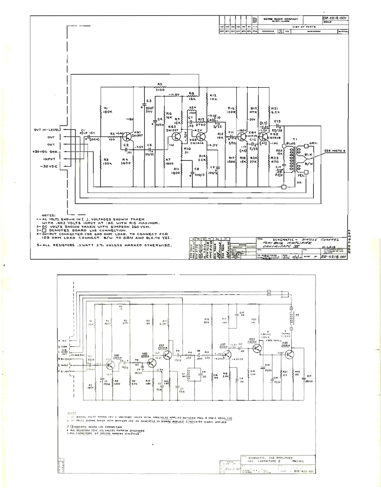
I
I
I
I
(:i!
!
r--,
-----------,
M
I
I
I
e,
OU'
""uVI;.\d
ou,-
I
:m>tF~")
OUT
t
+3avoe
eN0
'1
'HPUT
-30VO<;
~
I
I
I
f1QT'6:!t: L
"',
'601(
-.,'11
C3
"'
20Uf
l
SOV
~
..
,
WIlO'
.00
C2
I
, ,
..
v
.
0,
R)
R4
)SOW.
l~OO
I ,
~
""
VO~T
S
5"0""N
IN
(
).
VO,-TAC;"$
SHoWN
T"",
..
t<
5100
W'T~
.QO~
VOL..T!.
INPU"'t
AT
\)'..C w'T~
P"S
MA.
~
U"UM
.
t-
0<:
VOL-rS
SHOWN
,......',c"EN
W\'T)-\
SIMP~ON
2.40
"OM.
3-
0
OENOTE.S
aOAR,O
,""u6
C,QNNa(,,"'ON
,
-n_.e,v
R8
'Iol<
~'1
'0"
~7
fl
~R~;",
I I
'I"
1
""&~
'uo
1900
I
soKS
15'4
~:rK
RU
ce
e~:
1600
"T
5OO/J
,oo/t
4-0UTPUT
(,ONNEt.TI£.O
FO~
fr,OO
OHM
\..0"'0.
TO
C.ONNf:C.T
FOR
OATD
1tA000
CO"'AH
V I
_
'
''P'II''
,I
~
"
~$ClID"
'
oo..
- 1
.4
'1
O~
'-'
~"
-
02,e
-001
.....
I~W'_
S£E
NOT£.
"
~
'"
•.so
OWM
LOAO
C.ONNECT
e./w
TO
GAN
ANO
8\.lC...
TO
yel
. ..,
VI
..
'"'
oN
-
m'Io&
6CM£'11a."""C.
_
.$'''''''
C;~
L"
C
.,y
-fh'/VE£
+'
S-At..L..
A€,Sl&TOA.S
.
:SWA.-r'1
.5'7
.,
u
......
E.SS
~p..~'J(.£.D
O"~E.R.WISE...
•
'I
C
o
co
.....
co,
<
.""
,on
o0 .
~ClV
( t
..
"",
t
F-
t!I
~
lOY
.,
I,f
(,~
.~
~
•
.,~
~,
~
""''''Y4l'/"",
AI""L
/
~/FIf?
..
:t~~.~
'!
~~
~
~
~
t
.:
:~'
...
.
.
C?A;)r~/r/J'p
L:.
·
..2r
I
G.2t~
0
~y.~.~
' .
"",
~~
~
....
,
wn.
r~'"
1
=-
--
~
~
ih'~~~
~~~:"-:l
:-
~
~~
....
.
lr.;./
rhld_'
''
'"
.
~
~;'OZ'8""1
o--J
I
J
c.
,
r
~
Z
-5
'(lN.o,l
"'<}l
'
~
=.
NO
!f't
"- ,.., f I
V04.,.
<
.t
! I
... ...
!
~
o¥
,
l'
",
000,.
VOlt~
"~
"
ut:OoJ~c.tw(,t
jof
I"
OO(So
0
...
ft
~
£
V?
,,.,
~
,
~
0,
vo
u:'
s"'o
""
...
,
..
.:
t.
...
"'
''11
"
.....
~
O
l'f
leo
,..
~
''''
:.>
'C''!
c:}
_
N')
~
I~
""
.!
~~
l
!!..e
.s
I
Hp
'c
....
n
.,
,)-.
5,1'4"'
1.
....
'
PI.
It
.O
3
O,
N
Ot(.
...
rt:;
Q:)
......
I'tD
l
lJ'6
(.
u"""'
{Cr ...."
• "
I.
L
Rf..!oI.!-
tO
IQ
'a w
:;,.
UI'ILC~
J
"M
""":f
lJ
O"
.,
U<
Wl
ec
~
"
l.l
_
(;
~~
~~
$:
-_
~,
~N~~~
_ ~iII
~
t:!
~
n
.,
t;;
woS
«
r-
----;-;-=--11
~
-
.
,~
{
:
!/ot
~
!:'r~
'
;~!l!
A; ~U
'IC
~
M';.!l'"
....
"
"I.,
.'
':
...
fi!I
~"
,
~
,,!Jo
00
'

I
I
I
-;
I
~"
~
R?
,~
'O~
..
I
...
K
,
r-
,
-(
A
~.
-<
a
~
-(c
~
Cr
~r
(
,."
--(0
D-t-
f\~O
GNP.
'SK
+
-«
INJ"
VT
l'_~"
-<,
6 -
.(I.t.~
C4
"ll
2.
UF
,,(;
M
S~I'<
Z'<
R~
Li
<Z
,~O(
2:r')
,c:.
.<l7~,
U
I
I
.5
HY
I
I
L
__
_
I J
lie
!)ft;
N
iU
r'
()
L
't'~
·
S#O
~N
IN
( )
V()LTIi~~$
rA
X
L"N
f'o
r,<;
.OO(K.
....
o,
~
F
NP
l.!r
To
'piNS
j)
~
...,CJ
£
C!N
'-n=.
evE
,;q/>~ "
,":i'bd
C/'fs.)
J.lV
PI/T
rc
1'
''15
I9h'.PLI~/
~
.IZ
1 $
r.ro
,c"li!O
""
PIN
(;
{)I"
(
Kt:-
C''''
EP"",P
(C:V~
8V$~
ovr
) ,
VSE
2Q()
C"'s
F
O~
...
.
nv.!V.6N'{(J
nos
nMPLlr~R
.
l }
C4::,
YO'
TS
$HOWN
rRk~N
wt
"
~
$
,...,,...Sq,,,,
2 "
a1V
S t
rlO
IC
t97'
E 5 ",IC
~f
C;
.'YP
(.
,
S
I
Nb
/
C/!r
£~
SI
';N
A 4
/9oP"-LfifO
,
)) 0
II'.·OIC.ll!"~S
~OAJ:!D
£
(IG
CONN~
r:'''-t~,..
.)
,1)((
P
~SI$
-rgR
S
V
.z
tV
S"~
(p,L
E$:
$
Ml~IPKif
D
("JTh'fRllI'/
S~_
~)
l'Iu
.
C'Ap'
~C
r
"'O
R
:;
Io«"'~
V
N<..
I!~
·S
""I'I
~K
£'O
OTN
GN
wI'$C_
--<
.II,
NC.
4 c
o."'-
~
~",
-(0
u
~
D
--
<
l-
'
''~vr
---<t
8 -
I
I
I
r
I
I
I
I
I
I
I
I
I
I
r -
-'
-----
L-1-
I
I
j • !
.&
£
f>
Y ,
(f
r)
I
L
_,
I
I
t
--
-
'"
.~
&
l~
'0'
_J._;.
Cot'()()(J
CI
J~
,(./
l--rro;---l
(".
OJ
r.J '
~
I
'/
"~~r~
.~
co
I)f(
'-
I
,~.
r
.-
"5
\\0
"
11;
""
I
i ' "
""
"'"
~
I
;,.
'
-ro.S'
~~
'''''''
01--(;
~)
--i
I '
""
,~
~NI"14
·~,4
FL-
R1 .q CS
,,~
,,(
.o,~,.,,(
I)
li
e:
Sf6NI'JL
.,,,,
rs
5HQ
""''''''
(A'
( ) VOL.
TA
(S.t;J"
T.~Jt;
f'l
#f/''''
,
o~
VOL r s "
,-",
,
'r
rq
/'0.'$
D B-v,£j L
0,'1
II(~
~
"""
fr
C"I
)'j.
l
upu
r ro
r~/~
I'Nl
JJl..I
.cJl;k
J,S"
F4C
....-Ito,·""
11
,
1'1
C or I k e
~
,p
(CVI>
09u$
S
ovr)
. U$~
5~a_
7'P
r.K
,,!,
Ct'<
"'N
I
$
I'V_~_
z.)
()~
YOL;$
~H()WN
rA#(,~N
rflrlf
$I,~P~
N
C<.
C
""'M.
IVS
'''''
0
/(:111'£$
N ¢
.$,
::;~~
£
""
'.PI
d:"
S
,N
OIC-¥TES
$1($#-91".
r1P
PL
IL:o.
.JJ
OI
NOJCltrSS
fJtJ-9RO (c:.t;
CONNC'CTI(,)
NS
<I
J
IIl.L
.#£${$TOJPS
Y;,...
. S-.",
(<"NL£S$
NIVR
K
cl7
01'ffE.liJN
/
~E
.
~
}ftLt.
~/l
PflCI
(fl~S
{.,<.(
~ V/'f1. 4 1S
...-,h
.F
KE
a
f:1nt
ER
W/.J
i>
RIO
~,~
t;~
f
<~
ti'
:::
'~
..
~r
.
"'Y
,
N$
I
Cr
, 6
1
r ~.
s.
_I
'/~
5CH
I!
""
"TIC}
150
OCP
:;
eVE
....
MFL}:cr,eR
IT
.\1~Z
f.6
A
8''''~~S'O:>l
~TD
"':~:"'~'f"AAT
'S,eo.5
<
-00
'
..
-.;.
~/
--
.::-:
f-
~}
I
[
~o
b[
P
rp
2
11
11o
t"
J
...
..
[]
'--
.y/~,
.
.~$$
r
M)1'i
~
-r
,C
0-
a
.
$ ~C
HO"
l
~
~:;~
1"
,Q
'Q'
~
,tl'f
'<#1.
RI2
2~
.'.
~'"
"ru
S C
~e""AT'
I
C
-CUE
AMPuF'.-
U:t:
.,
KC C
.....
A:rRI,
APt
11
M
<o
2
r<;
I:'
8»02"
OJ
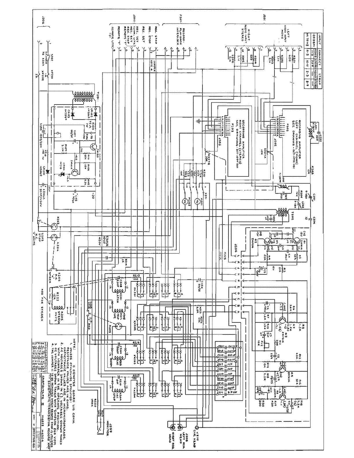
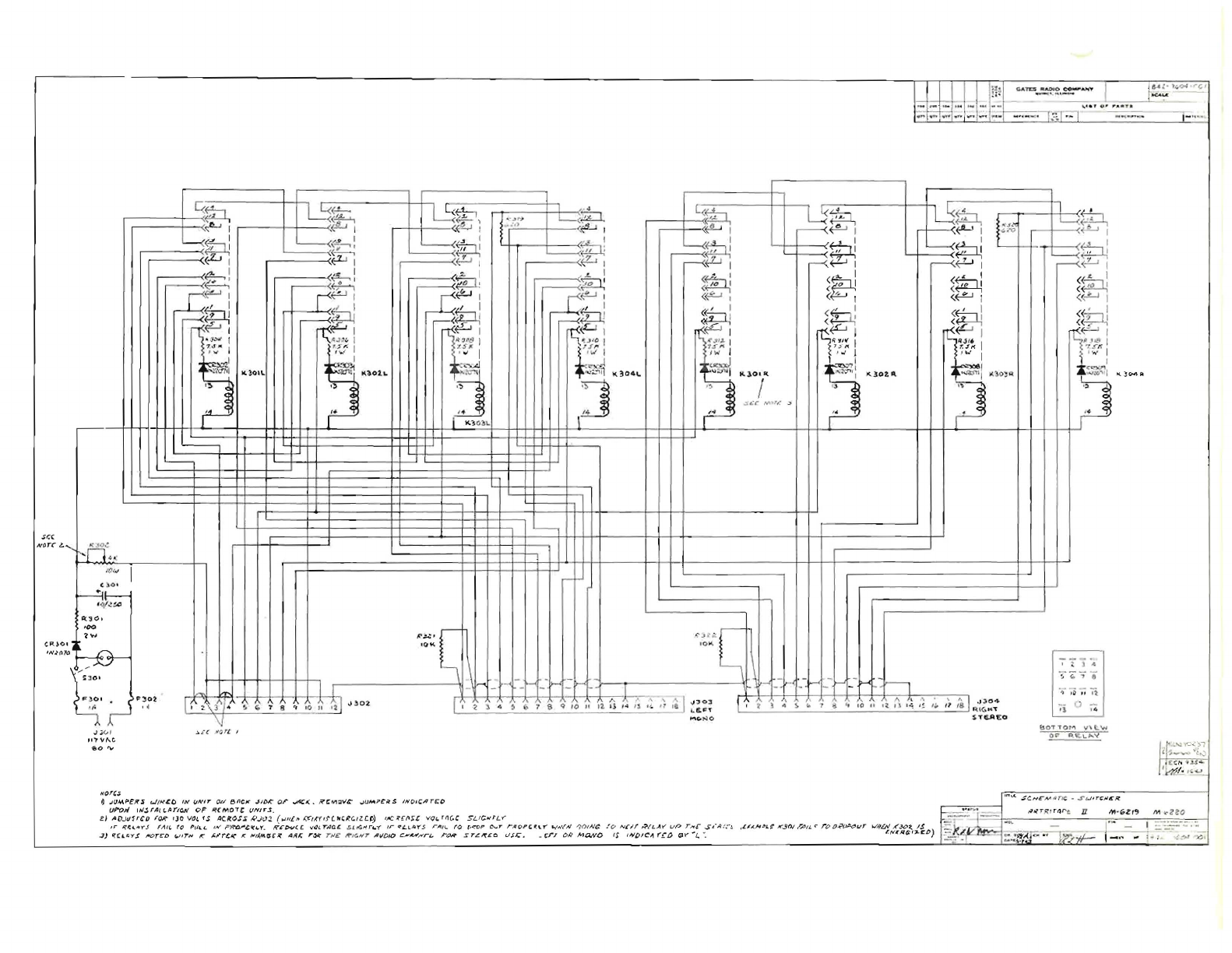
sr.(
N()n:
l.
C.FUO
'N~(l
Q.ATD
....
~~.
_
!!.
__
..,
~,:;
~
[/~
~~
L5~
1t
,
,.
C<~
~
l
..
'
rs~
,<!f--'-.
f
'"
~
;za.
i::
-w
{t?,
if'-' I (1iW I <
<!-'
I
.....
.
,)
(flU ,
r----<~
I
~I
I
~'"
, I
~
D!
~<~
~
L-.;j
~
,
~
I
+P.J
l-..(
~
b4::JJ
~Ttl
:
~,,;
~
'-
~
"
I
I-
'
~
" I
<.'L.J
I (
.:LJ
I
P,
~I
~
~.LJ
I
~I
r-<.
fL-'
I ,--(.
<-'-'
I
I
,;<
I
~
I . ,
(
~
~
• I
~r
:
.......
'
.-------<
Fl
:
~fMJ:
~
1(:1
I
~~
:&::1;
7
r-'
i,C
r'
< 0 I
I
~
I
~I
';t-J , <P ,
~
/,
I
<'~
I
«.LJ
,
~
t:Jl
r-<
~
~
~
(~
<~
«pJ
? ) . )
<.
I < I
n<~:
r-<
~
I
r~
rs~
w
I
~
I
A~
i
~
,
~~~I
"oJ'-
:'
I
.,,'8
I _
~
.J
I
O
I
tr",IJ.
1
~J}~
I
.,'"
~
',
{;'
I
'J'.5"
~
t/
J'I
'1j~
"'
J
~
7.<"
11
I
.
~
I
~
,
,,,
I
...
.
....
' 1
~
""~02.L
"",J
~
14.).011{
) I
~1d1~
1
lC.)o,~
:J
"'·:,.
...,
il
"I(,~04
...
_
,:Ito
'
~
I~
K102A.
'
...
~I
Klo;~
.
~
I
,3 /
L-
,
~
.>
" ., '. , ., c
c
~
,
:r
IAH'~
'"
C
,
,.
'.
i<
;
~
<j
i
K}
O~\.
,,:!0-4
AI
~
C--
'--
'---1
'
n
~
.;:..;
I
/I)
",
I
r-
'
~Q
'
'"
~
q/
~tA:J
1\3(h
.-
?w
.":
~
.>
"
~
-0"
'
O~
F-:B-
1
:.
1 ..t
~
~
:
::
lr-'
.
_
~
t-<
_-
I-
_-l>- _- h
~
'
~'
&
1 I
_
I
~
_J-<
-_
I--<
_-
I>-
':1>-
I
I~
""
I)
,~
" '1
G'
F ~
OI
•
~~o~
I
~
3
A/
...
!o
" T 8
..,
10
~
~
I
oJ
~
02
, I J
"..
~
....
'\
\
~
I
...
130)
r' t 1
~
~
~
.;
41
"
I~
II
I l
~}
I
~
j
~
'
;'
I
~
/8
f
q,~
~~':
-,- 0 -
1/
:
,,'
(:
l.
.to
:.
0-
"7
'&
q.
10
/1
1
1.
I;
/4
,'-
i"';'
,r
Ie
L
Eo""
'1
I A
J
;;
("
,
,1"'P'Vf\..C.
..
'"
'"
NQ
ru
-y
..l.~
'(
.
~IJ"
L
I
~
.J(JM.~~R5
"J
I
H~O
IN
f,JN
l r ~/
e,nc,c
..J
1iJJ:
()r
~.o(
•
.R'C"""::I'I~
..JUM;>~ilS
IN
p
,(;Arcc
uP'O.1"I
''''.lfA
l
l.~YlQN
cF
~CMOTC
1./1YJ,..l.
e)
IlO
.J
1I
1
rco
fOR""
'JO
\/Q,
fS
ACR.()S~
k'
.•
h':J.
(!Jill,.
('C'~Yf
f
("'~C.llC.t»
f
l'C?{fI~~
VQI.
ro1
(.C SU
C'<'L
Y"
il"\Co
N- O
IF
1i:'(4.."'Y.s
rA
I
l.
to
P r
il..L
f
N'
''=~'IIf4.Y
.
tiI:Pv
« ( ,,(}tT"I1C£
~
'IG.~
n.:(
Ir«"!.l.lilY.5
..-It/
!,..
fO
(,
IroP
c....r "'''' 0
''
(
\.''''
t.,IA'("1'I
~
(}(N
~
,'
(I
NClf~
E
L~
YV
P
r"'CSJ
'
IU,,-~
,LU
.
~"'l~KS()JI''''
(
L'r
o o
i.'f
~"r
w"~£#..(".30t
1$
~)
~'I..c::
y
.!
JIIOr-l:D
t.llr,..
K"
",,"r!;1<\
I{
/fI
(
l,.M.fJ~~
A/fl:
,~
r#£
If'JG.N""T
A!l
D
ID
t:.,6~
/"'
rL.
r
ON"
sr~If£O
U,H:.
_t:r.r
(),Q
Ma..vO
IS
IIIIi>IC,,!
(~n
(;1
........
1..
".
L
"'
~R(j;';J..C()
$TE..AEO
bOTTOM
v'lt..w
OF
~
'a
\.."..."
I
r-'''~:''
,
............
""'l,.,)
II:
C
... .,.
..
~/~
,,
'-'
'"<A.
.:;c.Hc
"....
~
rN;
_
-S""
j,J.
rt;"'tl!iR.
II'I
~
Ger'
M
,-:,zeo
..,-
r
~
..
-~
~
·::,~~~~'~

u
...
1'0
_~~~
.l
~
,
:;:
~"
P
""'''
~
. =
~
_
J.
!"
N..J
T£f
,
(,)
."!'$~O
-<'-'Of<:7
'"
F,D(~J
'''~,1?.J:"rp
I,/{
.I"/If(
FT~
«J
1f'e-M~VC
'/f/",,"CL
lY~/"";f~4
~"'eJ'"
7 f -I
(N/
,J,J~~
&101
~~~~~T
'#
Ct:F)
fJ!
;r~~
.r",'T':~c.7".:r
(J-
~ ..
_rjFC:~M
~"':h'
!/N//;f/l'£
L~C~TEP
PH
P~"'.IS
5
~
~
(ON
PI
F
t'i
t1~
.
'<.
t:'T-<C¥f
vN/r.
~7NI'.I~C;
TNiFSc
r?/NTJ
n
..rA',rC'",elY~f"
,l¥ACr,(;,o
.ITI'?£IV,I(/r.l./
-!oT/I.c.r
c.'A',r~
~T~
:
0®!JJ-(j'-0-0-(l)-@@-@@-@@
®@
-
@J
ib®
~
S-,l
J ·~C
oJt!1
.
~~
..
7
:...
_
___
_ _
~
_
~
!
t1_f
__
It~~
::.#or!
fl'!
-:
___
~
/)'~T'~
.,.
P~~'77'£
~v~,Prllii!.
tIE
I'AfEE;V
r-r'T
oJ-
....
~""4~
5001
'0"
SW3
•
R"
2
NOTES,
III
(0
;;;
10
"
Vfll"
-
f
-
.;p_'f8)
_
~
-
/
~
-)
(
$
6
~{M
\ • • ' I.
-:':'
:~:
-#
(-)
}w'lr;u
JVHI¥
,II
:
/
~
~~C
,
;;:.;r:!
~::r
J l
lr<
-
~
T
,
I'-f~~ii/
'"
;/:
.
f;
,,~r
.".
,,~
_/ .
t.......
,!r
"(
U
1/'.11:'7
/
-
l'
~
P
I
'
T
r..
s~oe
"$
"
HIrE
A
5004
-S"
R (CORD REMOTE
111£2"4
~"
,,~
~
#
s~oo
"r"
REO
..sL
?
~l
T8001
TB502
I,
~w,
Tel!
AND
8UL8
LOC
ATEO
IN
ONE
SWITCN NOUSING,
e_
NEON
BULB RESISTOR PART
OF
sw'
rCH ASS( MSLY.
,.-
-
--
--
-- -
----
-
--
---,
.0@@@@00@
@@
0«O@@S
e
fu
An~
H
r::
'~"
;;
n~
_
~~~
__
~:.
~
?_
s.:r..
;;~,;
___
.J
"c
-""/~
~
.
4.
.,
,..,
.V~~/'
I I
~
fi
~
n
§i.
S403
","
$403
..
3"
(SU,
I'>(
O
(l
N
IT
)
'
~
L
~
$jf
r~
..
,
r
,
f
·
.sw--
r
.::
~
..
~
J
'-
fJ!lO
, ,
~/vK-"
(
•
.."
.!"
..l
, .
.r"'
IiC.'
.I'>"
~
_
{"
i
';
~'
,,"
'
. ,,
-
__
p.
........
",
,c.
-'Ii"o"
J
----.---l
"'-
~:.'./"T
~!"
'
,:,
'1:;
.:
,J
..
..
.f'
~
.,
....
.,.
.(,-::.
"
~..t
(
f{//V(,
OI.II~1i>J:'"
C3~
""VI<..rr~.'~~
s,
.•
"n::ff£P
LO
f'ol
NLCTt
7(.(
ff~(?
::
,:
: .
J}'
)l"r
~I.
~
·-':':""
J . .... . .
...
. J
UI
:" I.
l!'-
T
~
~
S404
·2"
I II
5402
"4"
TB~OI
r040e
PLAYS",C/( REMOTE
/11&221
REMOTE
U"'T~.
CARTRITAPE

NOTES:
/.
A.C.VOq~ES
£,!OWN~:
VOLTAGES
SHOWN
T,.<ti<.EN
WITH
AUDIO
INPUT
-
ZOD8M
MATCHING
RZ07
MAX.
(REC.
LeVEL)
Z . DC VOLTAGES SHOWN
TAK
EN
WITH
SIMPSON
260
Vo,.., .
.3.0
DENOTES
BOARD
LUG
CONNECTION
.
CI
-'--
RI
16K
R3
eOK
RS
10K
R6
C 5.1
K.
RII
SIK
Rf3
3.Q
K
TI
BLUE
20/501'+
~2K
I
J
~
ti?)
VEL
GR
·
[)
XQ3
~
R8
cr
\'~~
(.Z)
7 .
S/(
+
-5.6
25/25
(.4
"q
-2.1
Hrr
RED
430
--L.-
C6
C8
es/es
RI5
SIK
R,17
3.6
I(
(~
75
)
-
<6·5
RIB
820
He:.
I
D,,"
1!If
Vl~ION
D"
~
Il.lIlfO
11(
.Jo,;
~~
~
,
eN
,
l0i
.
U2
C-
o, e tc ""/,,, " I S U
i"
$"
c..
/fi
J;
19
..
?
l
I'~/~'
A'
So
h/f.:l
1.
3
K.
""""L
1
~?
7(J
Ree,flOK
R.2.3
ZOOK
t-------ilf------ill------t-----:-+I
CI~
"T'
.47UF
IOOV
----L-C13
--r---
470
Res
10"
(.43)
-17
~
(.
21
-1.3
CI4
-L.::.
~%s
RZ
3.
GK
RI:I
L4
5.1K
+1,00/6
RIO
2.
2K
RIZ
RI4
'.K~
••
oj
1""0
4
ie,
R.IG
-L..
Rlq
10K
1~~
ZK
Rei
5.1 K
R.2/l
~47K
RC!6
820~
t:
I
---------..,!
I
~
~!
J t t t t
r---------------
L
________
=r_...J
4.
INPUT CONNECTED..
FOR
600
OHM
To
CONNECT
FOR
150
OHM
I
NPUT
CONNECT
6/W
TO
YEt.
AND
Bll<
.
TO
GR.N
.
S .
mRES'-SIQR~
yz
_
WA
i T
s1
~
UNL~3~!:'1~'3~~
.
D
~THERWfS£
.
6 .
UNh,ESS
0IMRWISE
S
PECIFIED
,
RESISTANCE
V A
LU
ES
A R E
~
2
HMS
.
CAPACITORS
LAUF._
,:!_~LESS
MARKED
OTHERWISE.
-lU
I-I--IZ,
'
...
ClI:t:U=>:J
0W
o
::)ch
Z
il:>Il.Il.
Z
\;j>
o
\!)(I')
:2~~
,
~
....
~ E
SCHEMATIC-
SINGLE
CHANNEL
RECORDI
N G
AMPL
I
FI
E R
CARTRITAPE
II
Mf>353
¢
M6354
""
C
DR
0"1
D L
DAT£q
q(4
ENG
,
A.."i
i"
~I"'
,
I
t)
.r.~f
S
HEE:
T 10
8Z7-/OQ4
-
001
Table of contents
Popular Storage manuals by other brands

Seagate
Seagate Barracuda ST310215A installation guide

Nexsan
Nexsan E18X installation guide

HP
HP P9000 user guide

Sans Digital
Sans Digital EliteSTOR ES316X12HP Quick installation guide

Compaq
Compaq StorageWorks 4000 - RAID Array White paper

Seagate
Seagate 3.5-inch Pushbutton Backup External Hard... Specifications


