GE Consumer & Industrial WSLP1500J How to use

GE Appliances
General Electric Company
Louisville, Kentucky 40225
31-9189
GE Compact Washer
WSLP1500J
WSLS1500J
Technical Service Guide
SEPTEMBER 2009
GE Consumer & Industrial
TEMP
LOAD OPTIONS
CYCLES
START
PAUSE
POWER
ULTRA
CLEAN

– 2 –
IMPORTANT SAFETY NOTICE
The information in this service guide is intended for use by
individuals possessing adequate backgrounds of electrical,
electronic, and mechanical experience. Any attempt to repair a
major appliance may result in personal injury and property
damage. The manufacturer or seller cannot be responsible for the
interpretation of this information, nor can it assume any liability in
connection with its use.
WARNING
To avoid personal injury, disconnect power before servicing
this product. If electrical power is required for diagnosis or test
purposes, disconnect the power immediately after performing the
necessary checks.
RECONNECT ALL GROUNDING DEVICES
If grounding wires, screws, straps, clips, nuts, or washers used to
complete a path to ground are removed for service, they must be
returned to their original position and properly fastened.
GE Consumer & Industrial
Technical Service Guide
Copyright © 2009
All rights reserved. This service guide may not be reproduced in whole or in part
in any form without written permission from the General Electric Company.

– 3 –
Table of Contents
Back Cover...........................................................................................................................................................................19
Brake Control Motor ........................................................................................................................................................32
Circuit Board Connections............................................................................................................................................17
Component Locator Views...........................................................................................................................................15
Control Features................................................................................................................................................................ 9
Control Panel and PCB ................................................................................................................................................18
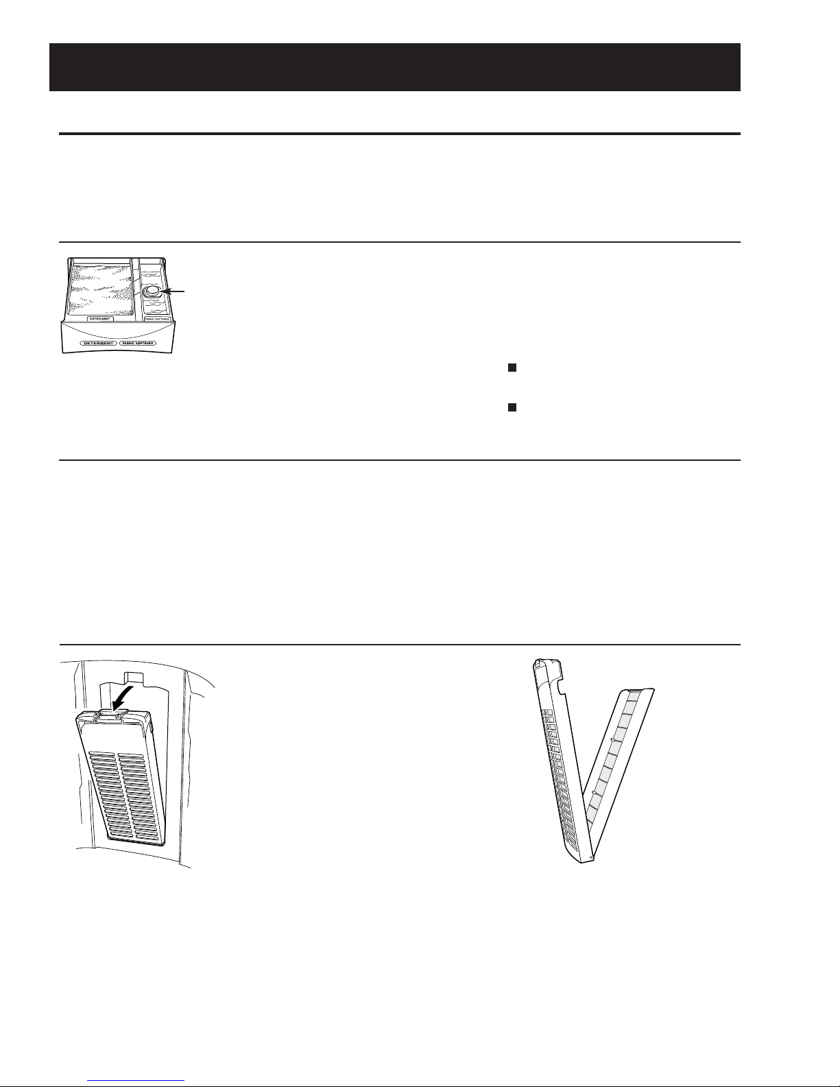
Dispenser Assembly........................................................................................................................................................25
Drain Pump .........................................................................................................................................................................25
Error Codes ..........................................................................................................................................................................34
Fuse.........................................................................................................................................................................................24
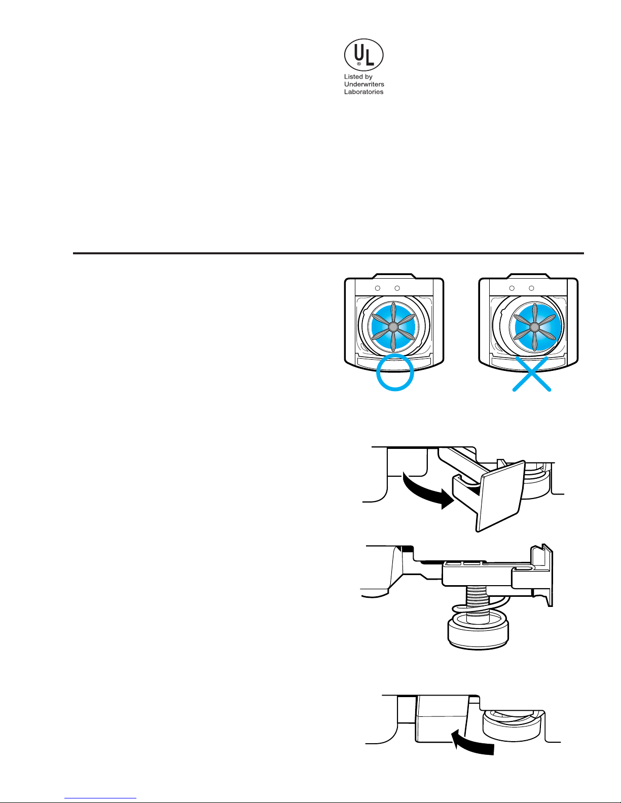
Installation ........................................................................................................................................................................... 6
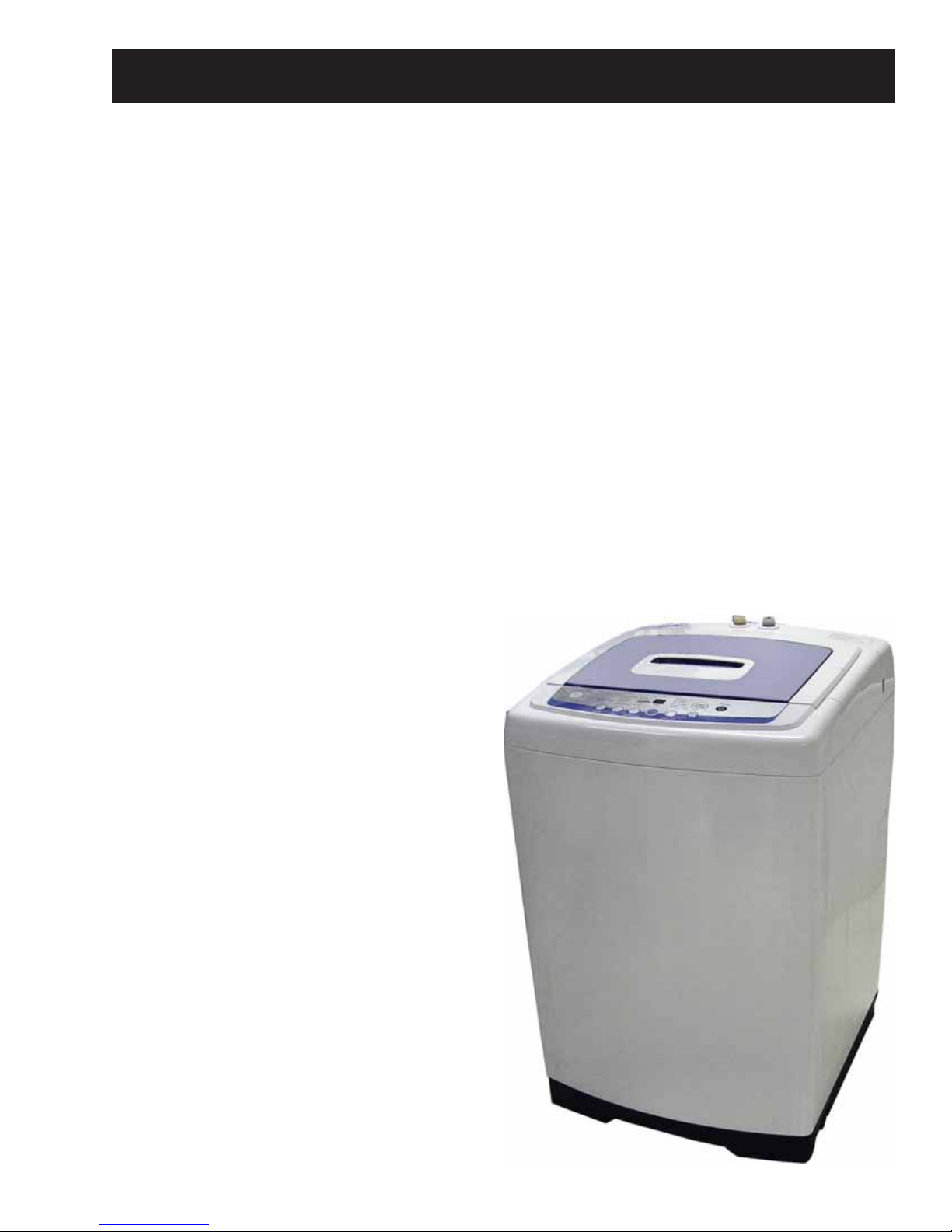
Introduction......................................................................................................................................................................... 5
Lid Switch and Harness .................................................................................................................................................23
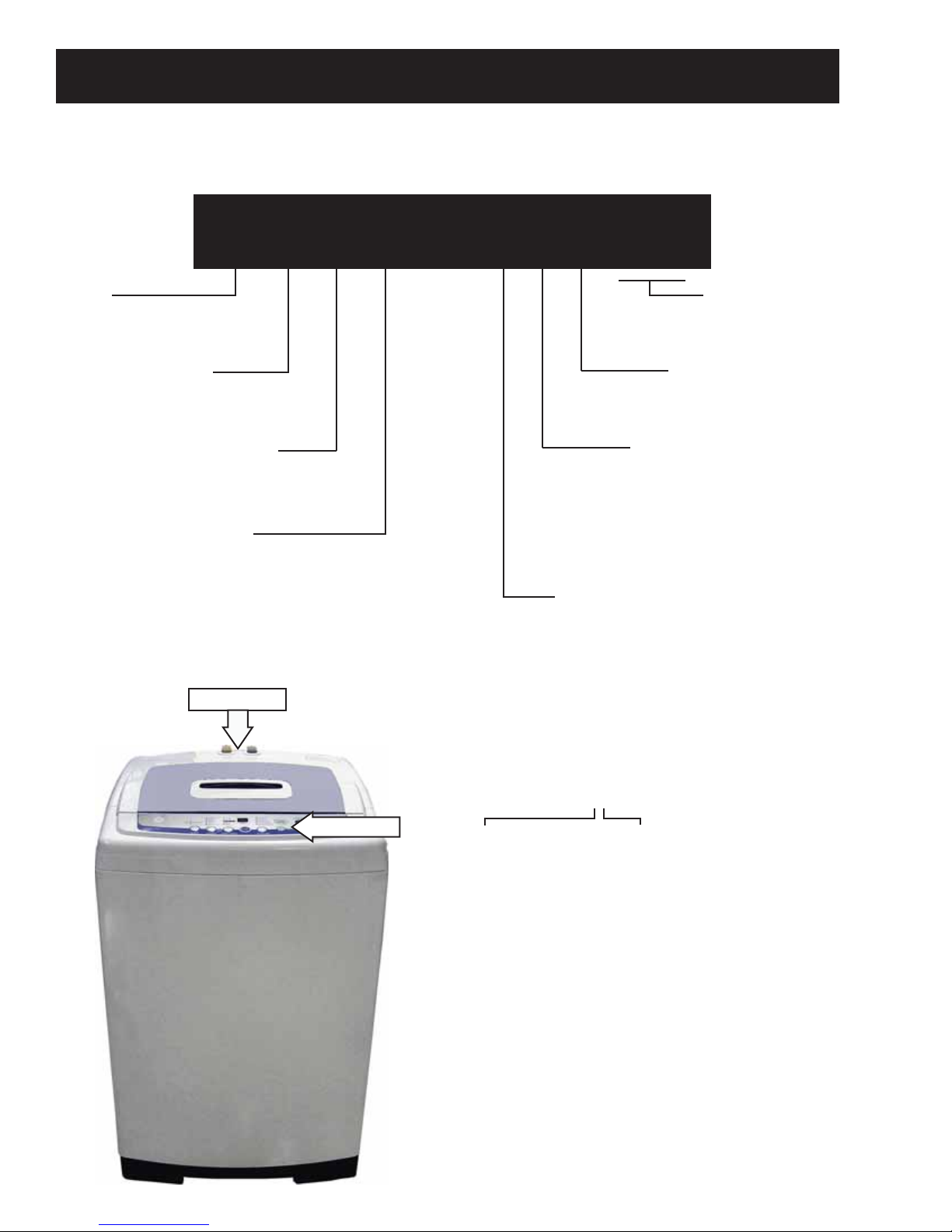
Nomenclature .................................................................................................................................................................... 4
Outer Tub and Suspension Assembly.....................................................................................................................29
Pressure Sensor.................................................................................................................................................................21
Schematic.............................................................................................................................................................................36
Service Test Mode.............................................................................................................................................................35
Shaft Assembly..................................................................................................................................................................33
Shaft Assembly and Brake Overview .....................................................................................................................31
Special Features................................................................................................................................................................ 8
Top Cover..............................................................................................................................................................................24
Troubleshooting ................................................................................................................................................................34
Unbalance Switch.............................................................................................................................................................22
Warranty .............................................................................................................................................................................37
Wash Basket ....................................................................................................................................................................... 28
Washer Components......................................................................................................................................................18
Washing Motor and Belt................................................................................................................................................27
Water Valve.........................................................................................................................................................................20

– 4 –
Model Number
Nomenclature
Capacity/Configuration
L = Large
W S L S 1 5 0 0 J W W
Feature Package
S = Unitized Compact
Control Platform
S = Stationary
Engineering Revision
Color
WW = White
Model Year
F - 2005
G - 2006
H - 2007
J - 2008
K - 2009
Voltage
0 = US Voltage
Brand
W = GE Washer
The nomenclature plate is located on the back
below the top cover.
The mini-manual is placed in an envelope
located under the control panel.
The letter designating
the year repeats every
12 years.
Example:
T - 1974
T - 1986
T - 1998
Serial Number
The first two numbers of the serial number
identify the month and year of manufacture.
Example: AS123456S = January, 2009
A- JAN 2009 - S
D - FEB 2008 - R
F - MAR 2007 - M
G - APR 2006 - L
H - MAY 2005 - H
L - JUN 2004 - G
M - JUL 2003 - F
R - AUG 2002 - D
S - SEP 2001 - A
T - OCT 2000 - Z
V - NOV 1999 - V
Z - DEC 1998 - T
Mini-Manual
Nomenclature

– 5 –
Introduction
The new GE Compact Washer has the following features:
Electronic One-Touch Controls with LED readout simplify cycle selection and provide accurate cycle•
times.
One-Touch Loading Sensing eliminates guesswork and helps reduce water waste.•
Ten wash cycles provide a setting for almost every load, from heavy cottons to casual synthetics;•
includes settings for light- to heavy-soil regular, whites, colors, casual and delicate fabrics.
Three wash/rinse temperatures ―A variety of temperatures provides great wash results and longer•
fabric life.
Four water levels match the water level to each load to reduce water waste per cycle.•
One Wash/Spin Speed ―Provides reliable cleaning performance for regular clothes.•
Custom Wash Cycle ―Saves a favorite cycle for future use.•
Dispenser adds diluted detergent and fabric softener at the correct time during the wash or rinse cycles.•
Overflow Protection ―Activates the drain pump whenever water reaches overflow level during a•
temporary stop, waiting action, or spin action. Overflow also sensed 3 times during a wash or rinse cycle.
Built-in Status indicators display certain associated error codes.•
The wash tub is constructed of durable stainless•
steel.
UV stabilizers are utilized on the control panel,•
top cover, and lid to prevent yellowing when
exposed to sunlight.

– 6 –
Installation
Location
Washer must be installed on firm flooring.•
Concrete flooring is best, but wood base is
sufficient, providing floor support meets FHA
standards.
Washer should not be installed on rugs or•
exposed to the weather.
Install or store washer where it will not be•
exposed to temperatures below freezing.
Minimum clearances between washer and•
adjacent walls or other surfaces are: 2” either
side, 2” front, and 3” rear.
Minimum vertical space from floor to overhead•
shelves, cabinets, ceilings, etc., is 96”.
Closet doors must be louvered or otherwise•
ventilated and have at least 60 square inches
open area for washer only, or if the closet
contains both a washer and dryer, doors must
contain at least 120 square inches of open area,
equally distributed.
Note: The clearances stated are minimums.
Consideration must be given to providing adequate
clearances for installation and servicing.
60 sq. in.
(387.1 sq. c
m
60 sq. in.
(387.1 sq. c
m
Closet door
Plumbing
Water pressure must be 10 psi minimum to 150 psi maximum dynamic pressure measured at faucet.•
Water temperature on household water heater should be set to deliver water at 120° to 150°F (50° to•
66°C) in the washer when HOT wash is selected.
Shut-off valves should be supplied for both hot and cold water lines.•
Drain water into a standpipe or laundry tub. The discharge height must not be less than 30” nor more•
than 8’ above the base of the washer. The standpipe must be 1½” minimum inside diameter and must be
open to the atmosphere.
g
Cable Tie
Laundry Tub
GEA00044
Cable Tie Cable Tie
Stand Pipe
GEA00045
(Continued next page)

– 7 –
Electrical Wiring
National Electrical Codes or prevailing local•
codes and ordinances must be followed.
120V, 60Hz must be supplied and connected to•
an individual, properly grounded branch circuit,
protected by a 15- or 20-amp circuit breaker or
time delay fuse.
Wiring must be 2-wire with ground.•
Electrical Rating
Voltage AC......................................................120
Hertz ...................................................................60
Total connected load amperage ........10.0
For use on adequately wired 120-volt, 15-amp
circuit having 2-wire service with a separate ground
wire. This appliance must be grounded for safe
operation.
Leveling the Washer
Excessive vibration will occur if the washer is not
leveled. This will also trip the unbalance switch and
stop the washer. Check to ensure the washer is
level. With the door open, the spin basket should be
centered in the opening as shown in the “leveled”
view. If the spin basket is not in the center or
“unleveled” as shown at far right, level the washer
as follows:
Note: Be careful not to kick or step on the leveling
locks.
Pull out the leveling locks located at the bottom•
front of the left and right sides of the washer.
This releases the spring loaded leveling feet.
The washer will attempt to automatically level•
itself.
Check level at body panel line and adjust as•
necessary.
Push leveling locks back in.•
Manually level the rear feet (side to side).•
Leveled Unleveled
GEA00042

– 8 –
Detergent and Fabric Softener Dispenser Drawer
The detergent and fabric softener dispensers
will automatically release their contents at
the proper time during the cycle.
To Use the Detergent Dispenser:
Add measured detergent to the dispenser.
Make sure detergent is spread evenly and
is level.
To Use the Fabric Softener Dispenser:
Use only liquid fabric softener. Pour into
dispenser, using amount recommended
on package.
Do not fill any higher than the top of the
maximum fill tower.
Never pour fabric softener directly on
clothes. It may stain them.
Cleaning the Detergent and Fabric Softener Dispenser Drawer
1. Remove the drawer by opening it fully
then tilting the front of the door up.
Pull out.
2. Rinse the drawer with water. If necessary
use a soft cloth to wipe off any debris.
3. Line up the drawer with the opening and
push the dispenser drawer straight in.
Lint Filter
Clean the lint filter inside the wall of
the wash basket once a week for best
filtering results.
To remove:
Press the tab at the top of the filter and
pull out.
To clean:
Open the filter. Clean the filter with
a toothbrush.
Maximum
Fill Tower
Before starting the washer:
•Load the laundry in the washer.
•Add the detergent and fabric softener to the dispenser drawer.
Special Features

– 9 –
Control Features
(Continued Next Page)
EXTRA LARGE
LARGE
SOAK COLORS
WHITES
DELICATES
SPEED WASH
LOAD SENSING
CUSTOM CYCLE
WASH
RINSE
SPIN
COLD
HOT WARM
LOCK
HOLD 3SECS TO
LOCK/UNLOCK
CONTROLS
MEDIUM
SMALL
EXTRA SMALL
HEAVY DUTY
EST. MINUTES
REMAINING
TEMP
LOAD
OPTIONS
ULTRA
CLEAN
CYCLES
DELAY WASH
1 to 18 HOURS
POWER
START
PAUSE
About the control and indicator settings.
Before starting the washer:
Load the laundry in the washer.•
Add the detergent and fabric softener to the dispenser drawer.•
To Use Automatic One-Touch Washing
The LOAD SENSING feature automatically senses the size of your load, tub fills with the appropriate amount
of water, and calculates the amount of wash time required to complete the cycle.
NOTE: When using the LOAD SENSING feature, it is normal for the pulsator to rotate before water fills in the
tub.
To choose the automatic• LOAD SENSING feature, press POWER ON/OFF. LOAD SENSING is the default
water setting. Manually selecting a load size cancels LOAD SENSING.
Select the desired• CYCLE, OPTION and water TEMP setting.
Then press• START/PAUSE.
The• COLORS indicator light will light up automatically unless you have selected one of the other LOAD
SENSING cycles such as WHITES, DELICATES, SPEED WASH, CUSTOM CYCLE or ULTRA CLEAN.
Then simply press• START/PAUSE.
NOTE: When the cycle is operating, the OPTIONS LED flashes. When the washer is in PAUSE, the LED does
not flash.
START
PAUSE

– 10 –
To Choose Your Own Cycle Selections
Soak+Wash Soak+Wash+Heavy Wash+Rinse Wash+Heavy Wash Rinse Wash Rinse Spin
Cycle +Rinse+Spin Duty+Rinse+Spin +Spin Duty+Rinse+Spin +Rinse +Spin Only Only Only
COLORS X X X X X X X X X
WHITES X X X X X X X X X
DELICATES X X X X X X X X X
SPEED X X X X X X X X X
WASH
CUSTOM X X X X X XXXX
CYCLE
ULTRA X
CLEAN
POWER ON/OFF
Press the POWER ON/OFF button to turn on the control panel.
WASH OPTIONS
Choose the wash options you would like to include in the cycle. Press the WASH OPTIONS button until all
the options you want to include are lit. More than one option can be selected.
1
2
LOAD SIZE
The water level should just cover the clothes. Adjust the load size accordingly. Loosely load clothes no
higher than the top row of holes in the washer basket.
3
WASH CYCLE
These wash cycles control the length of the washing process. The chart on the following page will help
match the WASH CYCLE setting to your specific laundry needs. When a cycle is selected, the automatic
temperature that the machine defaults to can be changed to whatever temperature you desire.
4
(Continued next page)

– 11 – (Continued Next Page)
The control can add an additional 4 wash cycles to each washing process. Each additional wash cycle adds
approximately 16 minutes.
To add additional wash cycles:
• Select a cycle using Automatic One-Touch Washing.
• Press the START/PAUSE pad.
• Anytime after the START pad is pressed, if the OPTIONS pad is pressed, the display will show 1.
• Pressing the OPTIONS pad again will change the display to 2. Selections from 1to 5are available.
NOTE: Once a selection is made, the control will automatically add additional time to the Est Minutes
Remaining display. 1is the normal wash cycle without additional time added.
When the SPIN (only) option is selected, spin cycle time can be adjusted by pressing the OPTIONS pad after
the cycle has started. The display will show the actual minutes remaining in any SPIN (only) cycle.
Default Wash/Rinse Temperatures
Colors For easy care and wrinkle-resistant items. WARM/COLD
Whites For heavy to lightly soiled cotton, household HOT/COLD
linens, towels, work and play clothes.
Delicates For lingerie and delicate fabrics with COLD/COLD
light to normal soils.
Speed For one or two lightly soiled items
WARM/COLD
Wash that are needed quickly.
Custom Manually selected options of water
WARM/COLD
temperature and wash options
saved for future uses. (See NOTE 1.)
Ultra Maximizes detergent efficiency by adding
WARM/COLD
Clean water in steps and slowly diluting the
detergent to the standard level. (See NOTE 2.)
NOTE 1. To use CUSTOM CYCLE, set the CYCLES selection to CUSTOM CYCLE. Select TEMP and OPTIONS
choices. Press START/PAUSE pad. Control remembers, and the next time CUSTOM CYCLE is selected, the
most recent settings will be displayed. CUSTOM CYCLE always utilizes LOAD SENSING. Load size cannot be
locked in.
NOTE 2. The washer partially fills, (approximately 75%) then begins to agitate for approximately 30 seconds.
The washer will then pause and continue to fill for about 10 seconds, then agitate. It repeats this process, in
varying degrees and stages, 4 times before the tub is at the correct water level and the machine completes
the wash cycle.

– 12 –
Twenty minute SOAK function occurs only when selected. This time has not been added to the ALL TIME1.
column.
When one or more additional rinse cycles are selected, this shorter ADDITIONAL RINSE SPIN time is used2.
for all rinse cycles except the final rinse cycle. The final rinse cycle uses the FINAL SPIN time. The time
from this ADDITIONAL RINSE SPIN column has not been added to the ALL TIME column.
The actual fill time is a function of water flow rate and may be more or less than the time specified. If3.
more time is needed, the countdown will pause. If less time is needed, the control deletes the remaining
fill time.
The rinse water valve flushes fabric softener from dispenser for 75 seconds ((10’ on / 5’ off) -5 times) at4.
the beginning of the last rinse cycle only.
Time-Table of Function
(Continued Next Page)

– 13 –
About the control lock.
The control lock feature only locks the control during a cycle. Control lock does not lock the control in the
standby mode.
To activate control lock, press and hold LOAD and OPTIONS pads simultaneously for 3 seconds while the
washer is in a cycle. The display will alternate between CL and time remaining.
(Continued Next Page)

– 14 –
Water System and Filtering
Weight Recognition Function (Load Sensing)
The weight recognition function measures the washing load before water is supplied.•
The weight recognition function is canceled when water level key is pressed prior to the completion of•
weight recognition function.
If the current water level is above the lowest level at the beginning of weight sensing, it is automatically•
set as a high level.
If you change wash cycle after sensing weight, the high water level is automatically selected regardless•
of the water level decided by the sensing of weight.
Water Supply Function
Relations between water level, frequency, and water supply capacity are as follows:•
If the water level does not reach the selected level within 60 minutes after starting water supply, the•
Water Supply Error (7E) is displayed.
Supplementary water supply is performed during every washing or rinsing operation. The steps are as
follows:
Supply water to the water level selected.•
Perform the ACTIVATE operation for 1.5 minutes.•
Sense the present water level after stopping motor.•
Compare the present water level to the water level selected.•
If present water level is less than the water level selected, supply water to the water level selected. If•
present water level is greater than the water level selected, continue the washing or rinsing operation.
Total time of supplementary water supplying is not over 30 seconds.•
LEVEL GALLONS FREQUENCY (kHz)
EMPTY 0 25.2
EXTRA SMALL 8.00 24.1
SMALL 10.6 23.43
MEDIUM 12.4 23.03
LARGE 13.2 22.80
EXTRA LARGE 19.6 22.13
Water Level Frequency Chart

– 15 –
Component Locator Views
(Continued Next Page)
Top View
304 Stainless Steel Wash Basket
Tub Cover
Pulsator
Lint Filter
Water Valve Assembly
Water Inlet Ports
Unbalance Switch
Pressure Sensor Fuse

– 16 –
Component Locator Views (Con't)
Rear View
Tub Outlet Hose
Belt
Pressure Sensor Hose
Suspension Rod
Drain Pump
Drain Hose Connector
Pump Cleanout
Dispenser Drawer

– 17 –
PCB (Printed Circuit Board)
Circuit Board Connections
CN1 - Door Switch, Unbalance Switch, Pressure Sensor
CN2 - Line Voltage
CN3 - Neutral, Neutral to Water Valve Solenoids
CN4 - Washing Motor
CN5 - Washing Motor, Washing Motor Condenser
CN6 - Water Valve Solenoids, Brake Control Motor, Drain Pump Motor
CN1
CN3 CN6
CN2 (BLK)
CN5 (RED)
CN4 (WHT)

– 18 –
Washer Components
Control Panel and PCB
The control panel is located on the front of the top
cover. The control panel consists of an LED display,
and an 8 push-button keypad that operates a
printed circuit board (PCB).
The PCB is supplied with 120 VAC at PCB locations
CN2 pin 1 to CN3 pin 2.
A 12-amp fuse is installed in the white neutral line
and is located under the rear cover. (See Fuse.)
Caution: To prevent damage to the control panel,
place a cloth or towel over the front of the top cover.
5. Place the control panel face down on the
protected top cover.
Screw Cover
Notch
4. Slide the control panel to the left, then lift the
panel from the top cover.
3. Remove the 2 Phillips-head screws that attach
the control panel to the top cover.
Note: In the following step, 9 tabs located inside the
control panel are engaged in 9 corresponding slots
in the top cover.
Control Panel Removed from Top Cover
CN3
CN2
WARNING: Sharp edges may be exposed when
servicing washer. Use caution to avoid injury and
wear Kevlar gloves or equivalent protection.
To remove the control panel and PCB:
The control panel is attached to the top cover with 2
recessed Phillips-head screws (1 on each side). It is
necessary to remove 2 screw covers to access the
screws.
Open the lid.1.
In the notch provided, insert a straightened2.
paper clip or small flat blade screwdriver, then
pry and lift the 2 screw covers (1 on each side),
from the top of the control panel.
(Continued next page)

– 19 –
Back Cover
Removal of the back cover provides access to the
water valve, pressure sensor, unbalance switch,
fuse, and lid springs.
The back cover is held to the rear of the top cover
with 2 Phillips-head screws and 4 tabs. The tabs are
located inside the back cover. After removal of the
screws, the back cover can be lifted straight up.
BACK COVER
TOP COVER
Before reapplying power, check for proper•
button operation, press each button and listen
for an audible click.
When installing the control panel to the top•
cover, before sliding the panel toward the right,
make sure all panel tabs are engaged with slots
in the cover.
Caution:
To prevent misalignment of the control panel•
selector buttons to the PCB, when installing the
PCB to the control panel route the wiring as
shown below.
Make sure all screw locations on the PCB fully•
contact the control panel before installing the
screws.
7. Place the PCB wiring side up and note the wiring
locations and routing, then disconnect the
wiring from the PCB.
6. Remove the 5 Phillips-head screws that attach
the PCB to the control panel. Place the control
panel and the cloth or towel aside.

– 20 –
Water Valve
The water valve consists of a valve body and 3
solenoid coils. It is only available as a complete
assembly. Each solenoid controls a specific water
function.
Each coil on the water valve assembly has an•
approximate resistance value of 1.2K Ω.
The water valves receive power from the PCB.•
When energized, there should be approximately•
120 VAC at the appropriate coil.
3. Disconnect the 3 wire harnesses from the valve.
VALVE COVER
4. Lift the water valve straight up and remove the
valve from the top cover.
The water valve is located at the rear center of the
top cover.
To remove the water valve:
Remove the back cover. (See1. Back Cover.)
Remove the 3 Phillips-head screws and lift the2.
valve cover from the valve.
CN6
CN6
CN6
CN3
Rinse Water Hot Water
Cool Water
This manual suits for next models
1
Table of contents
Other GE Consumer & Industrial Washer manuals
Popular Washer manuals by other brands

Alliance Laundry Systems
Alliance Laundry Systems CCN020HNF manual

Proline
Proline FP1012WH instructions

Beko
Beko WMY 91443LB1 user manual

Fisher & Paykel
Fisher & Paykel DE60FA2-96983 Use and care & installation instructions

Whirlpool
Whirlpool EXPERT 1200 Service manual

Panasonic
Panasonic NA-F95AR1 Operating & installation instructions