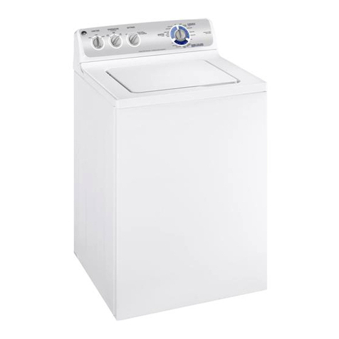
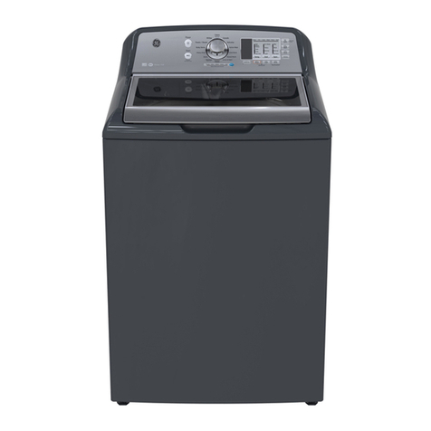
GE WDSS4120 How to use

C
C
PUB # 31-9081 07/01
TECHNICALSERVICEGUIDE
GEConsumerHomeServicesTraining
TopLoadWasher
WDSS4120

IMPORTANTSAFETYNOTICE
Theinformationinthisserviceguideisintendedforuseby
individualspossessingadequatebackgroundsofelectrical,elec-
tronic,andmechanicalexperience.Anyattempttorepairamajor
appliancemayresultinpersonalinjuryandpropertydamage.The
manufacturerorsellercannotberesponsiblefortheinterpretation
ofthisinformation,norcanitassumeanyliabilityinconnection
withitsuse.
WARNING
Iftheinformationinthismanualisnotfollowedexactly, a fireor
explosionmayresultcausingpropertydamage,personalinjuryor
death.Ifyousmellgas:
- Donottrytolightanyappliance.
- Donottouchanyelectricalswitch;donotuseanyphonein
thebuilding.
- Immediatelycallthegassupplierfromaneighbor’sphone.
Followthegassupplier’sinstructions.
- Ifyoucannotreachthegassupplier,callthefiredepartment.
WARNING
Toavoidpersonalinjury,disconnectpowerbeforeservicing
thisproduct.Ifelectricalpowerisrequiredfordiagnosisortest
purposes,disconnectthepowerimmediatelyafterperformingthe
necessary checks.
RECONNECT ALLGROUNDINGDEVICES
Ifgroundingwires,screws,straps,clips,nuts,orwashers
usedtocompleteapathtogroundareremovedforservice,they
mustbereturnedtotheiroriginalpositionandproperlyfastened.
GEConsumerHomeServicesTraining
TechnicalServiceGuide
Copyright©2001
Allrightsreserved.Thisserviceguidemaynotbereproducedinwholeorin
partinanyformwithoutwrittenpermissionfromtheGeneralElectricCompany.
!

ImportantSafetyInformation ................................. 1
GeneralInformation
Dispensers......................................................... 3
MovingandStorage ........................................... 4
SpecialityTools .................................................. 5
GeneralOperationDefinition .............................. 6
TechnicalInformation ............................................ 7
ComponentTestingInformation ............................ 8
InternalMotorDiagramandSchematic .............. 10
WiringDiagramandSchematic.......................... 12
TimerCycleChart............................................... 14
TroubleshootingProcedures
Waterrelated.................................................... 15
Timerdoesnotadvance................................... 16
Motordoesnotoperate. ................................... 16
Agitation............................................................ 17
Spin .................................................................. 18
Disassembly Procedures
ControlHoodAssembly ................................... 20
ControlHoodEndPanels................................. 20
Timer ................................................................ 20
TemperatureandSpeedSwitch....................... 21
Pressure Switch .............................................. 22
GraphicPanel .................................................. 22
LoadingDoor.................................................... 22
Agitator, DriveBellandSealAssembly ............ 23
InstallingDriveBell ........................................... 24
ServiceAccessPanel,FrontPanel ................. 25
MotorandMountingBracket............................. 25
PumpandBeltRemoval .................................. 26
MotorDisassembly .......................................... 27
IdlerleverandPulley ........................................ 27
MotorDriveBelt................................................ 27
CabinetTop ...................................................... 28
DoorSwitch...................................................... 28
Water(mixing)Valve ........................................ 28
TubCoverandGasket ..................................... 29
WashtubandBalanceRing ............................. 29
OuterTub ......................................................... 29
DrivePulley,HelixandBrake ........................... 30
“MilkStool”andBearingAssembly................... 31
Transmission Assembly................................... 32
UpperBearingAssembly ................................. 32
FrictionRing..................................................... 32
ExplodedViews................................................ 33
BrakePadKitWH49X10027............................ 39
HubandSealKitWH01X10151 ....................... 40
DriveBellandSealKitWH43X10024 .............. 42
Table of Contents

1
WARNING
!
To reduce the risk of fire, electric shock, serious
injury or death to persons when using your
washer, follow these basic precautions:
• Read all instructions before using the washer.
• Refer to the Grounding Instructions in the
Installation Manual for the proper grounding of
the washer.
• Do not wash articles that have been previously
cleaned in, washed in, soaked in, or spotted
with gasoline, dry-cleaning solvents, or other
flammable or explosive substances as they give
off vapors that could ignite or explode.
• Do not add gasoline, dry-cleaning solvents, or
other flammable or explosive substances to the
wash water. These substances give off vapors
that could ignite or explode.
• Under certain conditions, hydrogen gas may be
produced in a hot water system that has not
been used for two weeks or more. Hydrogen
gas is explosive. If the hot water system has
not been used for such a period, before using a
washing machine or combination washer-dryer,
turn on all hot water faucets and let the water
flow from each for several minutes. This will
release any accumulated hydrogen gas. The gas
is flammable, do not smoke or use an open
flame during this time.
• Do not allow children to play on or in the
washer. Close supervision of children is
necessary when the washer is used near
children. This is a safety rule for all appliances.
• Before the washer is removed from service or
discarded, remove the door to the washing
compartment.
• Do not reach into the washer if the wash tub is
moving.
• Do not install or store the washer where it will
be exposed to water and/or weather.
• Do not tamper with the controls.
• Do not repair or replace any part of the washer,
or attempt any servicing unless specifically
recommended in the User-Maintenance
instructions or in published user-repair
instructions that you understand and have the
skills to carry out.
• To reduce the risk of an electric shock or fire,
donotuseanextensioncordoranadapterto
connect the washer to the electrical power
source.
• Use your washer only for its intended purpose,
washing clothes.
• Alwaysdisconnectthewasherfromelectricalsupply
beforeattemptinganyservice.Disconnectthe
powercordbygraspingtheplug,notthecord.
• InstallthewasheraccordingtotheInstallation
Instructions.All connections for water, drain,
electrical power and grounding must comply with
local codes and be made by licensed personnel
when required. Do not do it yourself unless you
know how!
• To reduce the risk of fire, clothes which have
traces of any flammable substances such as
vegetable oil, cooking oil, machine oil, flammable
chemicals, thinner, etc. or anything containing
wax or chemicals such as in mops and cleaning
cloths, must not be put into the washer. These
flammable substances may cause the fabric to
catch on fire by itself.
• Do not use fabric softeners or products to
eliminate static unless recommended by the
manufacturer of the fabric softener or product.
• Keep your washer in good condition. Bumping or
dropping the washer can damage safety
features. If this occurs, have your washer
checked by a qualified service person.
• Replace worn power cords and/or loose plugs.
• Be sure water connections have a shut-off valve
and that fill hose connections are tight. Close
the shut-off valves at the end of each wash day.
• Loading door must be closed any time the
washer is in operational fill, tumble, or spin. Do
not attempt to bypass the loading door switch by
permitting the washer to operate with the loading
door open.
• Always read and follow manufacturer’s
instructions on packages of laundry and cleaning
aids. Heed all warnings or precautions. To
reduce the risk of poisoning or chemical burns,
keep them out of the reach of children at all
times (preferably in a locked cabinet).
• Always follow the fabric care instructions
supplied by the garment manufacturer.
• Never operate the washer with any guards and/
orpanelsremoved.
Important Safety Information

2
• Donotoperatethewasherwithmissingorbroken
parts.
• Donotbypassanysafetydevices.
• Failuretoinstall,maintain,and/oroperatethis
washer according to the manufacturer’s
instructions may result in conditions which can
produce bodily injury and/or property damage.
NOTE: The Warning and Important Safety
Instructionsappearinginthismanualarenot
meanttocoverallpossibleconditionsand
situations that may occur. Common sense,
caution and care must be exercised when
installing,maintaining,oroperatingthewasher.
Always contact your dealer, distributor, service agent
or the manufacturer about any problems or
conditions you do not understand.
Proper Grounding and Polarization of
120 Volts Wall Outlets
For the safety of our customers and the service
technician ALL appliances have a three–prong power
cord and MUST be connected to a properly
polarizedAND grounded wall outlet.
This information was written for those who do not
understand grounding and polarization of a wall
outlet.
A 120 volt wall outlet must always be wired as
shown below.
L1
0
V.A.C.
115±12
V.A.C.
115±12
V.A.C.
Neutral
side
Round
grounding
prong
Ground Neutral
Explanation
Polarization–This means that the larger slot must be
neutral and the small slot must be hot (live).
Mispolarized–The outlet is miswired so that the larger
slot is hot (live) and the smaller slot is neutral.
Grounded–Thismeanstheroundholeconnectioniscon-
nectedtoearthgroundthroughaconnectiontothemain
powerpanel.
Ungrounded–Theroundholeconnectionisnotcomplete
to earth ground and/or the main power panel.
Grounding Instructions
WARNING
!
• To avoid the risk of electrical shock or death,
do not alter the plug.
• Do not remove grounding prong when installing
grounded appliance in a home that does not
have three wire grounding receptacle. Under
no condition is grounding prong to be cut off
or removed. It is the personal responsibility of
the consumer to contact a qualified electrician
and have properly grounded three prong wall
receptacle installed in accordance with
appropriate electrical codes
• To avoid the risk of electrical shock or death,
this equipment must be grounded.
This equipment MUST be grounded. In the event of
an electrical short circuit, grounding reduces the risk
of electric shock by providing an escape wire for the
electric current. This unit is equipped with a cord
having a grounding wire with a grounding plug. The
plug must be plugged into an outlet that is properly
installed and grounded.
Consult a qualified electrician or servicer if grounding
instructions are not completely understood, or if
doubt exists as to whether the equipment is properly
grounded.
Do not use an extension cord. If the product power
cord is too short, have a qualified electrician install
a three-slot receptacle. This unit should be plugged
intoaseparate60hertzcircuitwiththeelectricalrating
asshownintheappropriatedrawing.Modelsoperate
witha120supplyvoltage.
Important Safety Information
3
Dispensers
Fabric Softener
Dispenser
Fabric softener dispenser is
located on top of agitator.
Dispenser automatically releases
liquid fabric softener at proper
time during rinse cycle.
Fabric Softener Use Tips
•Liquid fabric softeners are
dispensed during final rinse.
Do not combine with bleach,
bluing, starch, detergents,
soaps, or packaged water
conditioners during rinse.
• Do not use fabric softener in
dispenser during DOUBLE
WASH cycle.
• Do not mix powdered
detergent with liquid softener
in dispenser or softener will
become gummy.
Fabric
softener
dispenser
To use dispenser, follow these steps:
1. Pour liquid fabric softener into dispenser, using amount
recommended on package.
2. Add water up to fill level, but do not exceed tip of fill arrow
indicator. FABRIC SOFTENER MUST BE DILUTED FOR USE.
• Do not stop washer during first spin or dispenser will empty
too soon.
• Never pour fabric softener directly onto clothes or spots and
stains may result. To remove softener stains, soak in soapy
solution or rub stain with soap and wash garment as usual.
• For best softener performance, set water level to medium or
higher.
3. Clean softener dispenser after
each use. Remove dispenser
housing from agitator by
squeezing lower part of
dispenser and pulling up on
housing while tilting slightly to
expose dispenser cup. Rinse
dispenser housing and cup in
hot soapy water.
Clean funnel shape in top of agitator and inside of agitator. Use
small brush on hole and slots in two funnel rings for thorough
cleaning.
After cleaning, re-install dispenser cup. Push dispenser housing
directly down onto top of agitator until firmly snapped together.
To prevent build-up, fill dispenser with clean water in wash
cycles when not using softener.
Bleach Dispenser
Bleach dispenser is located in
left front corner under loading
door.
Bleach
dispenser
Use only liquid bleach in
dispenser. To use powdered
bleach, add to wash tub with
detergent.
Carefully and slowly, pour
recommended amount of bleach into
dispenser during first washer fill. See
table.
Be careful not to spill undiluted
bleach. It is a strong chemical and
can damage cabinet finishes and
some fabrics if not properly diluted.
Follow bleach manufacturer’s label
for proper use.
LOAD SIZE BLEACH
(Max Amt.)
SUPER PLUS 1 cup
LARGE 1 cup
MEDIUM 3/4 cup
SMALL 1/2 cup

4
MovingandStorage
Moving Washer to
New Location
Replace shipping plug under motor
and shipping brace in tub. Refer
to
Installation Instructions
for
proper procedures whenever
washer is moved. See illustration.
Shipping
plug and
location
in washer
Shipping
brace
old Storage and Non-Use Periods
WARNING
!
Explosive hydrogen gas may be produced in a hot water system
that has not been used for two weeks or more. Before using
washer, if hot water system has not been used for such a
period, turn on all hot water faucets and let water flow for
several minutes to release accumulated hydrogen gas. Hydrogen
gas is flammable: Do not smoke or use an open flame when
flushing water lines.
Cold Weather Care
If washer is delivered when outside temperature is below freezing or if
washer is stored in unheated room or area during cold months, do not
operate until washer has warmed to room temperature. Do not
install or operate washer where temperatures will drop below
freezing.
Cold Weather Storage
If washer must be stored in seasonal home or storage building, use
one of the following storage methods.
METHOD 1
1. Turn off water supply faucets and disconnect hoses. Drain water
from both hoses.
2. Add one gallon of non-toxic RV antifreeze (available from hardware
or recreational vehicle dealers) to washer tub.
3. Push in cycle selector knob and turn to SPIN.
4. Pull knob out and let washer spin for 1–2 minutes to drain water.
Some antifreeze will also be lost. (If you have a septic system,
contact antifreeze manufacturer and make sure it will not harm
system.)
5. Push in cycle selector knob to stop washer. Dry inner wash tub,
disconnect electrical plug, and close washer lid. If moving washer,
disconnect drain hose. Move and store washer ONLY in upright
position. To remove antifreeze after storage, run washer through a
complete cycle using ½ cup of detergent. DO NOT ADD CLOTHES
TO CYCLE.
METHOD 2
1. Push in cycle selector knob and turn to SPIN. Run through
complete spin cycle to remove excess water.
2. When spin cycle is complete, push in cycle selector knob to stop
washer.
3. Turn off water supply faucets and disconnect hoses. Drain water
from both hoses.
4. Dry inner wash tub, disconnect electrical plug, and close washer
lid. If moving washer, disconnect drain hose. Move and store
washer ONLY in upright position.
5. It is normal for some water to remain inside pump. To prevent
damage to washer and pump if remaining water freezes, allow
washer to warm to 24 to 48 hours after removing from storage, so
water can thaw before use.
Vacations and
Extended Non-Use
IMPORTANT: To avoid possible
property damage from flooding,
turn off water supply to washer
during extended periods of non-
use.
To prevent mold or mildew, leave
lid open so moisture inside
machine can evaporate.
When closing your home for
extended periods, have service
technician drain washer to avoid
stagnant water. Unplug cord from
electrical outlet. Disconnect hoses
from faucets.
Tilt washer back slightly
and slide shipping
plug into position
under washer

5
Speciality Tools

6
Thewasherusesareversingtypemotor,aspecialdrive
beltandanidlerassembly. Theidlerassemblyapplies
tensiontotheoutsideofthedrivebelt. However, the
loadingdoormustbeclosedforthewashertoagitateor
spin.
Duringagitation,themotorrunsinacounterclockwise
direction.Thespringtensionontheidlerpulleyapplies
tensionrequiredtoreducetheslackonthedrivebelt
andmaintainmaximumbelttomotorpulleycontact.
Thiseliminatesbeltslippageandensuresanefficient
washaction,evenwithextralargeloads.
Thebeltdrivesthetransmissiondrivepulleyina
counterclockwise direction. The pulley drives the
helix which is attached to the input shaft of the
transmission. This causes the input shaft to turn
inside of a roller clutch which is pressed into the
transmission cover.
This roller clutch acts as a bearing in a
counterclockwise direction allowing the transmission
gears to operate. The transmission’s rack and pinion
gear design produces a 210° agitation stroke at the
output shaft of the transmission which drives the
agitator. The brake assembly remains locked during
the agitation mode since no pressure is applied to it
bythetransmissiondrivepulley. NOTE: Duringthe
gentlecycle,itisnormalforthewashertostop
agitatingandpauseperiodically.
Afterthewashagitationiscompleted,thetimer
advances into the first spin. During spin, the motor
reversesturninginaclockwisedirectiontospinthe
wateroutofthewashtub.Thecombinationofwater,
washtubandloadweightcausethedrivebelttensionon
theidlersideofthebelttoovertaketheidlerspring
pressureallowingthebelttoslackontheoppositeside.
Thisreducesthebelttopulleycontactandallows
slippingbetweenthebeltandpulley.
Aswaterisremovedbythedirectdrivepumpandthe
momentumofthewashtubincreases,theidlerspring
tensiongraduallyovercomesthebelttensionremoving
thebeltslack.Thiseventuallyincreasesthebeltto
pulleycontactuntilmaximumspinspeedisachieved.
Thedrivepulleyturnsclockwiseridinguptherampsof
thehelix,exertingpressureonthebrakeandforcingitto
releasefrombrakepads.Thehelixdrivestheinputshaft
ofthetransmission,andwhentheinputshaftturnsina
clockwisedirectiontherollerclutchlocksontotheshaft
causingtheentiretransmissionassemblytoturn.None
ofthegearsinthetransmissionareoperatingatthis
time.Thehubofthewashtubisattachedtothe
transmissiontubeandrotateswiththetransmission
assembly. Thecentrifugalforcecreatedbythespinning
washtubcauseswatertobeextractedfromtheclothes.
Waterisintroducedduringthefirstspinto“SPRAY” the
garmentsandremovesudsfromthem.Theinitialspinis
followedbyrinseagitationtorinseawayanydetergent
residue.Thewasherfillsandthenagitateslikethewash
portionofthecycle.Followingrinseagitation,afinalspin
extractstherinsewaterfromtheclothespreparingthem
forthedryer.
General Information
Temperature
switch Pressure
switch
Timer
Agitator
Mixing
valve
Washtub
Transmission
Motor
Pump
Plastic
outer
tub

WasherTechnical Information
7
WDSS4120
Model WDSS4120
Power Source
Voltage AC 120 VAC 60 Hz
Amperage (Single Unit) 10 A
Motor horsepower 1/2
Dimensions
Cabinet
Height−overall 43”
Height of cabinet 36”
Width 27”
Depth 28”
Clearance−washer lid 17 1/2”
Weight
Crated 193 lbs.
Wash cycles 12
Water temperatures 4
Warm water mix 60% cold
40% hot
Water level Variable
Lowest 6.75 +/- 1”
Highest 14.25 +/- .75”
Water usage
Small setting – per fill 12 gallons
Medium 17 gallons
Large 20 gallons
Ex-large 24 gallons
Total water usage - small 21-25 gallons
Ex-large 47-50 gallons
Features
Self-cleaning lint filter
210° Agitation stroke
Fabric softener dispenser
Extra rinse
Motor speed 2 speed
Spin speed (revolutions per
minute)
640/427 RPM
Agitation speed (strokes per
minute)
Normal 69 SPM
Delicate 46 SPM
NOTE: Normal basket index is
approximately ¼”

Component Testing Information
!
WARNING
To avoid risk of electrical shock, personal injury, or death, disconnect power to washer before servicing, unless
testing requires it.
Illustration Component Test Procedure Results
L1 L2
2
1
Temperature switch Disconnect wires from component to
properly measure the resistance of the
component.
Place switch in the following positions
and measure across the terminals
below:
Hot / Cold L1-2
Warm / Warm L1-1, L1-2, L2-2
L2-1, L2-L1, 1-2
Warm / Cold L1-1, L1-2, 1-2
Cold / Cold L1-1
>1 Ω
>1 Ω
>1 Ω
>1 Ω
Mixing valve Measure resistance of terminals on
each valve.
Resistance across each valve.
Approximately 1000 Ω±10%
Timer Verify input and output voltage is
present.
Verify wiring is correctly connected to
the timer.
See timing sequence chart for functional
description of the component.
1
2
3
Pressure switch
Do not disconnect the pressure hose
from pressure switch to perform
measurements.
Measure resistance across the
following terminals on the pressure
switch:
Terminal 1 to 2
Terminal 1 to 3
Refer to wiring diagram/schematic for
correct contacts.
Air pressure that actuates switch is
determined by the water level of the
tub.
Continuity (no pressure)
Continuity (pressure)
Lid switch−SPST Disconnect wire terminals from switch.
Test terminals with switch closed.
Test terminals with switch open.
Continuity >1
Ω
Infinite 1 MΩ
Brake pad kit If washtub does not stop spinning
within seven seconds after opening
loading door.
If brake pads make noises.
Replace all three brake pads.
Apply a thin layer of silicone lubricant on
pads.
8

Component Testing Information
!
WARNING
To avoid risk of electrical shock, personal injury, or death, disconnect power to washer before servicing, unless
testing requires it.
Illustration Component Test Procedure Results
Motor
Type of motor:
Two speed
See following section “Internal Motor
Diagram and Schematic” for correct
wiring contacts.
Drain pump Verify drain pump is not clogged or
damaged.
Remove clog and verify proper operation.
Replace drain pump if damaged.
Transmission
assembly
Type of transmission:
640 rpm
If transmission locks-up, replace.
Drive belt Type of drive belt:
640 rpm
Refer to “Parts Manual” for proper
pulley size.
Refer to “Parts Manual”, to verify which
drive belt and pulley size is required.
Power Cord Measure resistance of wires. Continuity should be indicated on each
wire.
Verify polarity and grounding.
9

Internal Motor Diagram and Schematic
!
WARNING
To avoid risk of electrical shock, personal injury, or death, disconnect power to washer before servicing, unless
testing requires it.
10
Continuity exists between switch
terminal Rand Red wire.
Manually depress actuator.
Continuity broken between
switch terminal Rand Red wire.
Continuity exists between switch
terminal Pand Red wire.
Manually depress actuator.
Continuity broken between
switch terminal Pand Red wire.
Inoperative start switch.
Replace switch.
Inoperative high speed
switch. Replace switch.
Continuity broken between
switch terminal Pand Violet wire.
Manually depress actuator.
Continuity exists between switch
terminal Pand Violet wire.
Inoperative low speed
switch. Replace switch.
Motor switch checks OK.
NO
YES
YES
YES
YES
YES
YES
NO
NO
NO
NO
NO
Start
Terminals
High Speed
Terminals
Low Speed
Terminals
One or Two Speed Motors
4-5 ohms between Brown wire
and Red wire.
1-2 ohms between Blue wire and
Yellow wire.
1-2 ohms between Yellow wire
and Violet wire.
Continuity exists between Yellow
wire and White wire.
All motor windings checks OK.
Inoperative start winding.
Replace motor.
Inoperative high speed winding.
Replace motor.
Inoperative low speed winding.
Replace motor.
Inoperative common lead.
Replace motor.
Start
Winding
High Speed
Winding
Low Speed
Winding
Protector
NO
NO
NO
NO
YES
YES
YES
YES

Internal Motor Diagram and Schematic
!
WARNING
To avoid risk of electrical shock, personal injury, or death, disconnect power to washer before servicing, unless
testing requires it.
R
P
Y
BU
BR
W
Wire harness
connection
block
11
White
Brown
Blue
Yellow
Violet
Red
G
Y
BU
BR
W
R
P
RUN
START
Red
wn
White
Violet
Blue
Yellow
Bro
4P M
6P M
Aux.
Overload
protector
Yellow
Motor Assembly
(two speed motor)

Wiring Diagram
!
WARNING
To avoid risk of electrical shock, personal injury, or death, disconnect power to washer before servicing, unless
testing requires it.
Wiring Diagram
!
WARNING
To avoid risk of electrical shock, personal injury, or death, disconnect power to washer before servicing, unless
testing requires it.
12
12

Schematic
!
WARNING
To avoid risk of electrical shock, personal injury, or death, disconnect power to washer before servicing, unless
testing requires it.
13

Timer Cycle Chart
!
WARNING
To avoid risk of electrical shock, personal injury, or death, disconnect power to washer before servicing, unless
testing requires it.
CYCLE / FUNCTION
WATER
TEMPERATURE
SELECT
MOTOR
SPEED
CYCLE TIME
hh:mm:ss CYCLE / FUNCTION
WATER
TEMPERATURE
SELECT
MOTOR
SPEED
CYCLE TIME
hh:mm:ss
SO
AK DELI
C
ATE
Fill & Agitate hot, warm, & cold S 0:02:22 Wash: Fill & Soak hot, warm, & cold - 0:02:11
Soak hot, warm, & cold - 0:12:04 Agitate hot, warm, & cold S 0:00:27
Spin - S 0:02:51 Soak hot, warm, & cold - 0:02:33
0:17:17 Agitate hot, warm, & cold S 0:00:27
Soak hot, warm, & cold - 0:02:33
OFF - - 0:03:43 Agitate hot, warm, & cold S 0:00:27
S
oa
k
h
ot, warm,
&
co
ld
-
0
:
02
:55
PREWA
S
H
S
p
i
n-
S
0
:
02
:
38
Fill & Agitate hot, warm, & cold F 0:05:04 Spin & Spray cold S 0:00:27
Pause - - 0:00:29 Spin - S 0:02:26
Spin - S 0:02:31 Pause - - 0:00:29
Pause - - 0:00:29 Rinse: Fill & Agitate cold S 0:02:31
0:08:33 Pause - - 0:00:29
S
p
i
n-
S
0
:
02
:
31
RE
G
ULAR
0
:
23
:
04
Wash: Fill & Agitate hot, warm, & cold F 0:14:04
Pause - - 0:00:29
Spin - F 0:02:38 Pause for Extra Rinse - - 0:00:32
Spin & Spray cold F 0:00:27 Rinse: Fill & Agitate cold S 0:02:28
Spin - F 0:02:26 Pause - - 0:00:29
Pause - - 0:00:29 Spin - S 0:02:44
Rinse: Fill & Agitate warm, & cold F 0:02:31 0:06:13
Pause - - 0:00:29
Spin - F 0:05:31 OFF - - 0:03:43
0
:
29
:
04
Q
uick Wash
Wash: Fill & Agitate hot, warm, & cold F 0:05:04
Pause for Extra Rinse - - 0:00:32 Pause - - 0:00:29
Rinse: Fill & Agitate warm, & cold F 0:02:28 Spin - F 0:02:38
Pause - - 0:00:29 Spin & Spray cold F 0:00:27
Spin - F 0:05:44 Spin - F 0:02:26
0:09:13 Pause - - 0:00:29
Rinse: Fill & Agitate warm, & cold F 0:02:31
OFF - - 0:03:43 Pause - - 0:00:29
S
p
i
n-
F
0
:
02
:
44
PERMANENT
PRESS/KNITS 0:17:17
Wash: Fill & Agitate hot, warm, & cold F 0:08:04
P
ause - -
0
:
00
:
29
O
FF --
0
:
03
:
43
Spin - S 0:02:38
Spin & Spray cold S 0:00:27
Spin - S 0:02:26
Pause - - 0:00:29
Rinse: Fill & Agitate warm, & cold F 0:02:31
Pause - - 0:00:29
Spin - F 0:05:31
0:23:04
Pause for Extra Rinse - - 0:00:32
Rinse: Fill & Agitate warm, & cold F 0:02:28
Pause - - 0:00:29
Spin - F 0:05:44
0:09:13
O
FF -
0
:
03
:
43
14

Troubleshooting Procedures
!
WARNING
To avoid risk of electrical shock, personal injury, or death, disconnect power to washer before servicing, unless
testing requires it.
1. No hot water.
Possible Cause Result
Hot water supply faucet is closed. Open faucet.
Water supply is cold. Check water heater
Verify hot water hose is connected to hot side of inlet valve.
Kinked hot water inlet hose. Straighten or replace hose.
Clogged mixing valve screens, or screens in
inlet hose closes to supply faucet.
Disconnect inlet hose and clean or replace screen.
Clogged pressure hose. Remove and clean or replace hose
Failed pressure switch. Test switch and replace if failed.
Failed temperature switch. Test switch and replace if failed.
Failed hot water side of mixing valve solenoid. Test solenoid and replace if failed.
Failed timer. Test timer and replace if failed.
Failed electronic control. Test electronic control and replace if failed.
Broken, loose, shorted or incorrect wiring. Refer to appropriate wiring diagram.
2. No cold water.
Possible Cause Result
Cold water supply faucet is closed. Open faucet.
Kinked hot water inlet hose. Straighten or replace hose.
Clogged mixing valve screens, or screens in
inlet hose closes to supply faucet.
Disconnect inlet hose and clean or replace screen.
Clogged pressure hose. Remove and clean or replace hose
Failed pressure switch. Test switch and replace if failed.
Failed temperature switch. Test switch and replace if failed.
Failed cold water side of mixing valve solenoid. Test solenoid and replace if failed.
Failed timer. Test timer and replace if failed.
Failed electronic control. Test electronic control and replace if failed.
Broken, loose, shorted or incorrect wiring. Refer to appropriate wiring diagram.
3. No warm water.
Possible Cause Result
No hot water. See “No Hot Water” chart.
No cold water. See “No Cold Water” chart.
Failed mixing valve. Test mixing valve and replace if failed.
15

Troubleshooting Procedures
!
WARNING
To avoid risk of electrical shock, personal injury, or death, disconnect power to washer before servicing, unless
testing requires it.
4. Water fill does not stop at proper level.
Possible Cause Result
Failed pressure switch. Test switch and replace if failed.
Air leak in pressure hose Replace pressure hose.
Water in pressure hose. Blow air through hose to remove water.
Broken, weak, or missing mixing valve
armature spring.
Replace mixing valve.
Sediment on or under mixing valve diaphragm,
failed diaphragm, or armature binding in
armature guide.
Replace mixing valve.
A siphoning action started in washer will cause
water to be siphoned from washer during cycle.
Caused by drain hose being lower than washer
cabinet top.
Provide an air gap between drain hose and drain standpipe.
Make certain drain standpipe is at least 33” in height.
Failed electronic control. Test electronic control and replace if failed.
Broken, loose, shorted or incorrect wiring. Refer to appropriate wiring diagram.
5. Timer does not advance.
Possible Cause Result
Timer is designed to pause during fill periods.
Some cycles have pause (delicate cycle).
Allow completion of fill period.
Loading door is open. Close loading door. Loading door MUST be closed anytime the
washer is set to agitate or spin.
Washer will not fill. Timer pauses until pressure switch is satisfied.
Verify washer is not siphoning during rinse
cycle.
Provide an air gap between drain hose and drain standpipe.
Failed timer. Test timer and replace if failed.
Broken, loose, shorted, or incorrect wiring. Refer to appropriate wiring diagram.
6. Motor does not operate.
Possible Cause Result
Power cord not plugged in, blown fuse or
tripped circuit breaker at circuit panel.
Verify electrical power is present at outlet and unit is plugged in.
There is no internal fuse in the washer.
Loading door not closed or failed switch. Close door or test switch and replace if failed.
Motor overload protector has cycled. Wait two to three minutes for overload protector to reset. If
overload protector cycles repeatedly, see following chart.
Binding in upper or lower motor bearings. Remove belt and determine if motor shaft will spin. Replace
motor if shaft is locked up.
Motor is dead, electrical power is present. Test motor switch and windings.
Motor start functions fail or motor only hums. Test motor start switch and start windings.
Timer improperly set. Reset timer or try another cycle.
Failed timer. Test timer and replace if failed.
Failed electronic control. Test electronic control and replace if failed.
Broken, loose, shorted or incorrect wiring. Refer to appropriate wiring diagram.
16

Troubleshooting Procedures
!
WARNING
To avoid risk of electrical shock, personal injury, or death, disconnect power to washer before servicing, unless
testing requires it.
7. Washer smokes, overheats, and cycles on overload protector or switch actuator kicks in and out.
Possible Cause Result
Belt is tacky and does not allow proper
slipping.
Check belt and replace if failed.
Belt tension is too tight and does not allow
proper slipping.
Verify idler spring is properly connected.
Verify proper belt and pulley are installed.
Motor start functions fail. Test switch functions.
Bind in water pump. Replace pump.
Brake pads are binding. Free binding pads or replace pads.
Brake, transmission or motor have locked up
and will not turn.
Verify all components move freely. Correct binding component.
Failed timer. Test timer and replace if failed.
Incorrect voltage. Contact local utility company, or have a qualified electrician
check power supply voltage.
8. No agitation.
Possible Cause Result
Failed timer. Timer is designed to pause
(SOAK) during DELICATE cycle.
Test timer and replace if failed.
Failed pressure switch. Test switch and replace if failed.
Loose or broken drive belt. Adjust or replace drive belt.
Failed transmission assembly. Replace failed transmission assembly.
Sheared motor pulley roll pin. Remove drive motor and replace roll pin and any other damaged
components.
Motor overload protector has cycled. Wait two to three minutes for overload protector to reset. If
overload protector cycles repeatedly, see following chart.
Bind in water pump. Replace pump.
Loading door not closed or failed switch. Close door or test switch and replace if failed.
Failed timer. Test timer and replace if failed.
Failed electronic control. Test electronic control and replace if failed.
Broken, loose, shorted or incorrect wiring. Refer to appropriate wiring diagram.
9. Constant agitation.
Possible Cause Result
Failed timer. Test timer and replace if failed.
Failed electronic control. Test electronic control and replace if failed.
Shorted or incorrect wiring. Refer to appropriate wiring diagram.
17
Other manuals for WDSS4120
1
Table of contents
Other GE Washer manuals

GE
GE WBB5500 User manual

GE
GE GFWR4805FMC Assembly instructions

GE
GE Profile WPGT9350 How to use

GE
GE EWA6500 User manual

GE
GE GTWN4250DWS Manual

GE
GE Spacemaker WSLP1500JWW Assembly instructions

GE
GE GBSR1080 User manual

GE
GE Appliances WASR3110 User manual

GE
GE GFWR4805 Original instructions

GE
GE 175D1807P252 User manual