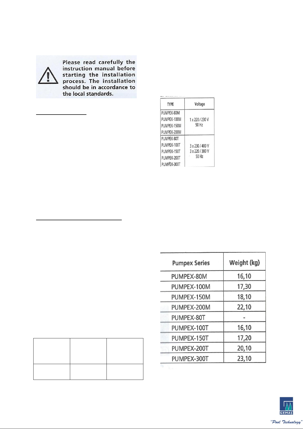
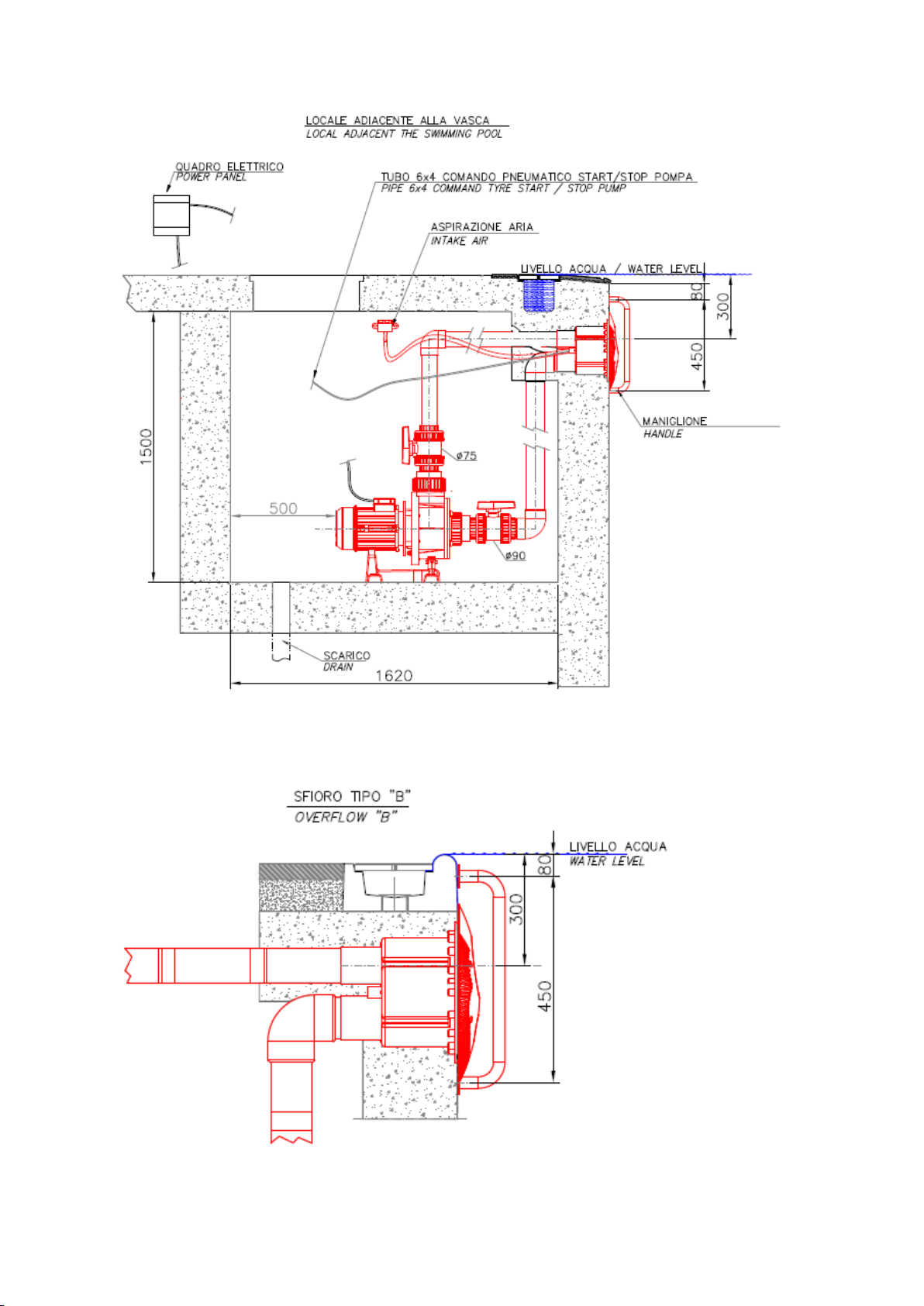
Gemas PUMPEX-80M User manual

GEMAS COUNTER CURRENT SYSTEM
USER MANUAL

PUMPEX MODEL PUMP
1. APPLICATIONS
The swimming pool pump model Pumpex has
a horizontal centrifugal construction. Its main
application is to circulate the swimming pool
pump water and normally it is installed before
the filtration equipment. The pump is
desinged to move about incoming and the
outcoming water from the chlorine disinfected
swimming pool. The PUMPEX pumps have a
removable basket for filtering of small solids.
2. TECHNICAL INFORMATION
2.1 Maximum enviroment temperature:
+50°C.
2.2 Water Temparature: From 0°C to 50°C
2.3 Maximum working pressure permitted: 2
Bar.
Note: The ram crash to be lower that 3kgs
2.4 Maximum inlet pressure: When the pump
Works with a closed valve the inlet pressure
should be lower than the maximum working
pressure permitted always.
2.5 Minimum suction pressure:
Type
Maximum
Suction
Maximum
Autosuction
Pumpex
5m
4 m
2.6 Self Priming: The PUMPEX pumps are self
priming up to 4 m height.
2.7 Electrical Details:
See also the charachteristics plate.
Water proof type: IP55
Isolation Class: F
2.8 Dimensions: See the drawing on the final
of this manual
2.9 Sound level: The sound pressure level of
the pump is lower than 70db.
2.10 Weights:

3. INSTALLATION
Normally the PUMPEX swimming pool pumps
are installed between the skimmer/balance
tank and the swimming pool filter.
The pump should be placed on a flat, solid
foundation with the shaft in horizontal
position and the prefilter cover uppermost. It
must be possible to remove the transparent
cover so that the prefilter basket can be
removed for cleaning.
The suction pipe must have as minimum the
same diameter as the pump suction line with
continuous slope in order to avoid long
priming times. If the suction line exceeds 10
meters, the extra pressure loss should be
considered.
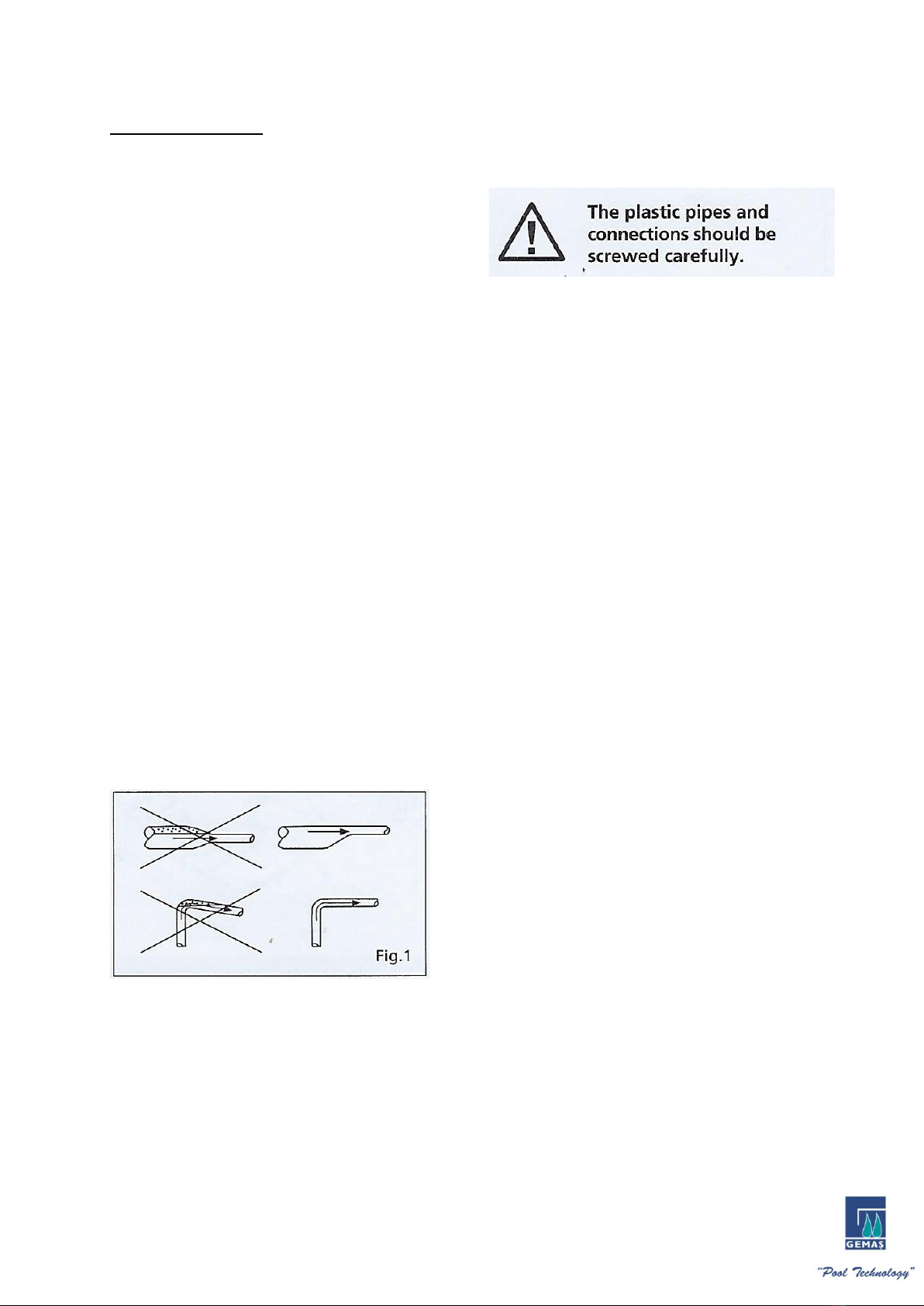
The pipes should be installed to avoid any air
leaksin its interior. The following drawing
shows a correctly fitted piping.
The pipes should be fitted in such a way that
any pressure varioation caused by
temperature changes do not effect the pump.
If the piping is very long and/or high support
the pump in front and behind. It is
reccomendable to put a retention or check
valve at the outlet.
In case of using a suction hose, it must be non-
compressible (with a reinforcement spiral).
The suction pipe/hose should be the shortest
possible in order to assure optimum working
conditions.
It’s recommendable to install shutting valves
the both sides in order to isolate the pump.
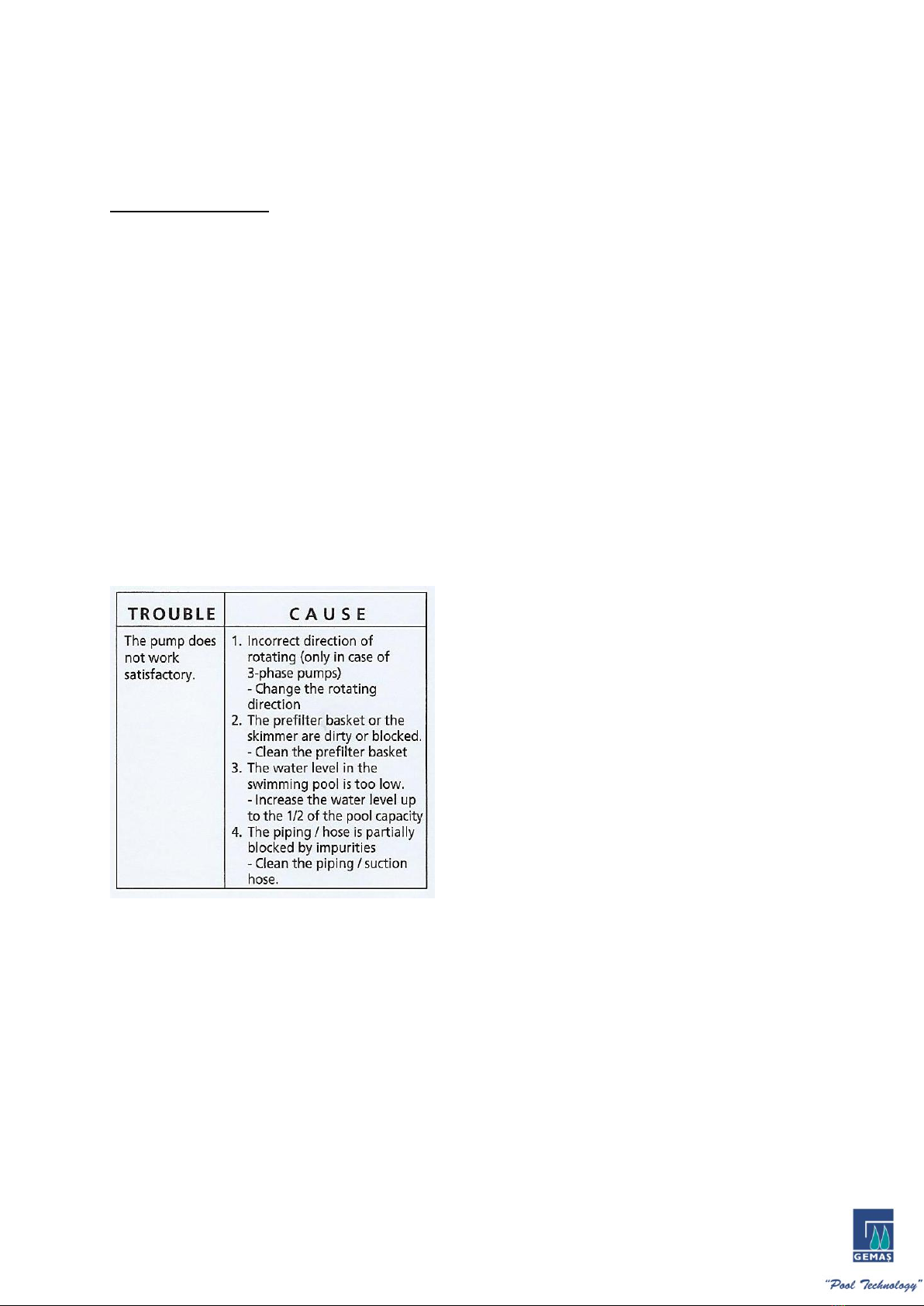
Note: The pump does not allow to work with
closed discharge valve as it may cause an
increase of the temperature and steam
formation which can damage the pump.
If there is any possibility of operating the
pump with discharge valve closed, it’s
necessary to connect one bypass/mud valve
on the discharge pipe in order to assure a
minimum liquid flow through the pump.

According to IEC N°364 publication,
the pump must be installed at minimum 2
meters from the swimming pool edge.
3.1 Ventilation: The pump’s motor is cooled
by fan, placed in the back side. You should
install the pump in a well ventilated place
(free from possible freezing), preferably in a
room.
a) If the pump is installed outdoors, it must be
protected with suitable cover.
b) If the pump is installed in a buried or
semiburied “case”, it is necessary to assure a
sufficient air entrance in order the motor
ventilation not to be damaged (the inside
temperature should not exceed the 50°C).
4. ELECTRICAL CONNECTIONS
Please make sure that the electrical
supply is interrupted nefore removing the
connection case cover or before any moving or
disassembling of the pump.
Electrical connections must be done by a
Professional and according to the local
standarts.
The pump must be connected to an external
switch.
The voltage and frequency are marked on the
characteristics plate. Please make sure that the
motor is suitable to electrical supply in the
network.
The motor should be connected to the electrical
supply as shown in the drawing, using a suitable
cable (watertight approved) and in accordance
to the local standarts.
4.1 Motor Protection: All version must be
connected to an external motor protector.
The pump must be connected to the outlet
mass and electircal installation must have a
differential circuit.

5. STARTING
Note: Do not start the pumps during its priming
or purging.
The pump is correctly primed when the water is
situated under the transparent lid.
The arrows on the pump housing indicate the
correct rotation.
In order to create a maximum suction capacity
during the starting, close the discharge valve,
start the pump and open slowly the discharge
valve. If the pump does not work correctly 5
minutes later, stop the pump check the water
level in both the suction pipe and in the pump
prefilter.
6. PREFILTER BASKET CLEANING
Please make sure that the electrical
supply is isterrupted and it is not possible to
be connected accidentally before to start
working with the pump. The filter basket
must be checked daily and cleaned if
necessary. Before opening the prefilter cover,
please close the suction and discharge valves.
After the filter basket cleaning, clean
also the filter cover gasket and put it in its
place. Then check if the pump housing is full
of water and if so, put the filter cover and fix
the cover nuts similarly. Open the charge and
discharge valves and start the pump.
9. TROUBLE SHOOTING
Note: High pressure cleaning is not allowed.
7. WINTERIZING
If the Pump will not be used during the winter,
remove all plugs and drain the pump and all
piping. To drain the pump, please take off the
drain plugs (5) from the pump housing. Do not

put the drainage plugs up till the pump will be
used again.
8. MAINTENANCE
Please make sure that the electrical supply is
interrupted and it is not possible to be
accidentaly connected before the pump to start
working. The pump is designed to operate
maintenance under normal working conditions.
The motor bearings are permanently lubricated.


INSTALLATION MUST BE DONE ACCORDING TO BELOW INSTRUCTION


INSTRUCTION FOR PVC APPLICATION
Cutting and chamfering:
Pipe should be cut square. A simple method of cutting pipes square is to wrap newspaper or similar
sheet paper around the pipe with no overlap of the edges. Mark line around pipe (felt pen is ideal). Cut
to line with a fine toothed saw.
Pipe ends should be chamfered at an angle of approximately 15° to about ⅓of the wall thickness with
a coarse file, surform tool or chamfering tool.
Solvent Weld Joints
Pipes up to 75mm may be jointed easily with solvent adhesives. Larger sizes require special
techniques
and require two men to make such joints.
1. Jointing Procedure. Mark depth of entry of the pipe into the socket and alignment mark.
2. Make small chamfer on the edge of the pipe end with medium file.
3. Roughen the outside of the pipe and the inside of the socket using sand paper or emery cloth up
to the entry mark.
4. Clean both surfaces and remove all dust, grease and swarf using a dry clean cloth and cleaner.
5. Stir adhesive thoroughly.
6. Apply adhesive without delay after cleaning, using a flat clean brush. Apply an even unbroken
layer brushing axially to the pipe end and socket mouth with a heavier layer on the pipe. Where
loose fits are found, the pipe should be given a second coat.
7. Immediately insert the pipe into the socket up to the entry mark, align pipe and twist 90 degrees.
Hold in position for a few seconds, then wipe off excess adhesive.
Solvent Weld jointing of large diameter pipes require special care and our Technical Service
Department should be contacted in case of difficulty. Always replace the lid of the can after making a
joint and follow the instructions on the can observing any warnings.
Joints should not be moved or disturbed for 10-15 minutes then the jointed pipe may be handled with

care. Allow 4 hours if the jointed pipe lengths are to be laid in a trench.
Allow 8 hours to elapse before applying working pressures or 24 hours for test pressures. With pipe
sizes up to 50mm, it is possible to reduce this time. Allow 1 hour for each 3.5 atmospheres of
pressure.
Brushes must be clean and dry before commencing solvent welding. Brushes must be thoroughly
cleaned after use by washing in cleaning fluid. Do not dilute solvent adhesive with cleaning fluid. Use
Solvent adhesive and cleaning fluid in a well-ventilated area. Keep away from naked flames and do
not smoke.
Always replace lids of containers. In any event, attention is drawn to the instructions printed on the
containers.
When laying continuous runs of pipe, joints may be made quicker than the setting times advised
above.
The joint will not be disturbed with long lengths, providing that the pipe is not twisted or the previously
made joint lifted out of place.
Rubber Ring Joints
Ensure that the spigot and socket are free from dust, grit, grease and as dry as possible. Insert pipe
into the socket without seal ring in place and mark pipe when it is fully inserted. Place seal in groove of
socket ensuring that seal is correct way round. Anger seal rings should be fitted with tapered section
facing the outside of the socket.
Apply jointing lubricant to the chamfer and the end of the spigot of the pipe or fitting only. Push the
pipe firmly into the socket up to the insertion mark previously made. If an expansion gap is required
the pipe is then pulled back by the desired amount.
This manual suits for next models
8
Table of contents
Popular Water Pump manuals by other brands

Pondmate
Pondmate PM2 13000W Operation manual

PERMCO
PERMCO Bushing Series Service manual

sauermann
sauermann OMEGA PACK Si-20 manual

SFA
SFA Sanifloor+ 3 installation instructions

ITT
ITT Goulds Pumps API 3171 Installation, operation and maintenance manual

Einhell Royal
Einhell Royal HW 1300 Niro operating instructions