Genexis FiberXport OCG-16m User manual

User manual
FiberXport® OCG-16m data/voice module
and optional OCG-12m CATV receiver module
Contents
1. Introduction
2. General warnings and remarks
3. Module user specification
4. Installation instructions
5. Powering the module
6. verview of the information provided by the various LED indicators
7. Connecting external equipment to the module
1 Introduction
The CG-16m is equipped with 2 RJ-11 ports to which conventional telephone sets can be
connected. Additionally the CG-16m is equipped with 4 RJ-45 10/100 Mbit/s ethernet ports to
which external equipment can be connected.
Furthermore an optional CG-12m CATV receiver module can be added to the CG-16m
data/voice module in the FXP-10 housing.
In order to help the end-user and/or installer to monitor the correct functioning, a set of LED-
indicators is present on the front of the CG-16m module.
The CG-16m data/voice module is specifically designed to be mounted in a FiberXport® FXP-10
housing. For this housing separate installation instructions are available.
2 General warnings and remarks
For adequate performance of the CG-16m module, the mounting instructions for the
FiberXport® FXP-10 housing (available separately) must be followed.
As noted in the FXP-10 installation instructions, the housing should have been mounted at a
location:
•with sufficient room (at least 10cm) at the right hand side of the FiberXport® to allow easy
connection of input/output cables
•with at least 10 cm of free space above the housing
•with at least 5 cm of free space at the left hand side of the housing
•N T in positon where the sun will be able to shine on the housing
•N T next to a radiator or behind a curtain.
The FiberXport® CG-16m is a Class 1 Laser Product according to IEC 60825-1.
This classification implies that the FiberXport® is completely safe for purposes of eye safety.
Nov 2005, Genexis B.V., Lodewijkstraat 1A, 5652 AC Eindhoven, The Netherlands, www.genexis.nl
GenexisGenexis

Important notes:
•Genexis does not assume responsibility for products that are not handled according to the
instructions contained in this user manual.
•Any claim for warranty or repair will be void when:
•pening the CG-16m data/voice module or the CG-12m CATV module.
•An attempt is made to modify, retrieve or reverse-engineer the software contained in
the CG-16m data/voice module.
•For the software, contained in the CG-16m data/voice module, the CG-16m software
license agreement is applicable; a copy of this license agreement is available upon request.
3 Module user specification
General
•Power supply: 12 V DC nominal, 14.4 V DC max
•Power dissipation: 7 Watt typical, 15 Watt max
•perating conditions: 0 – 35 °C
•Storage conditions: 0 – 70 °C
OCG-16m user telephone interface (RJ-11)
•2x RJ-11 connectors
•2x analog P TS line, each supporting 5 REN
•SIP based Voice-over-IP (rfc 3261)
•Speech codec G.711 (uncompressed)
•Standard Fax (G3) supported
OCG-16m user data interface (RJ-45)
•4x 10/100Base-TX (IEEE 802.3 Ethernet) RJ-45 connectors
•Full/half duplex
•Auto-negotiating
•Auto-MDI/MDIX
•Range 100 meters
OCG-12m user interface (F-connector)
•1x F-female connector (IEC 169-24)
•RF frequency range 47 - 862 MHz
Nov 2005, Genexis B.V., Lodewijkstraat 1A, 5652 AC Eindhoven, The Netherlands, www.genexis.nl
GenexisGenexis

4 Installation instructions for OCG-16m (and optionally OCG-12m)
1 Housing installation
There are 2 possible cases: either a complete FXP-10 housing is already installed or the
CG-16m will be installed simultaneously with a FXP-10 housing.
In case a FiberXport housing is already installed, it needs to be opened by removing the seal
(if present), unscrewing the locking screw on the front and removing the white cover.
In case a FiberXport housing is to be installed together with CG-16m module, please follow
the installation instructions for the housing (separately available).
In both cases the small covering plate at the right side of the white cover (as shown in Figure
1) needs to be removed by pushing it out from the inside of the cover.
Figure 1
Removal of covering plate
2 Mounting the OCG-12m CATV-receiver (Figure 2)
In case a CATV-receiver needs to be added, attach this module first. Place the module
directly onto the white base-plate, by positioning it on the four centering pins. Ensure the
module is correctly positioned to enable a good connection to the data/voice module (see 3.)
3 Mounting the OCG-16m data/voice unit (Figure 3)
Before attaching the CG-16m data/voice module, please verify that the fibers are spooled
and stored on the baseplate at the right hand side of the 3 fiber guiding stubs. In particular
verify that a fiber is not positioned over the CG-16m fixation pin hole or the cover screw
hole in the baseplate as shown in Figures 2 and 4.
Slide the CG-16m data/voice unit directly onto the baseplate as shown in Figure 3, using
the sliding guides. Make sure that the CG-16m fixation pin is clicked into the baseplate as
shown in Figure 4.
Automatically, a power connection is made with the CATV-receiver (if included).
Note: make sure that the CG-16m data/voice unit is pressed tightly onto the CATV-receiver
module, to ensure a good electrical connection.
4 Connecting the fiber cables
The incoming fiber cables should be equipped with a blue SC/PC connector for the data fiber
and a green SC/APC connector for the CATV fiber. Connect the blue SC/PC connector to the
CG-16m data/voice unit by plugging the connector into the black receptical. Connect the
green SC/APC connector to the CG-12m CATV-receiver by plugging the connector into the
metallic receptical. Ensure the connectors fit snugly to enable a good optical connection.
Note: the installer should ensure that the appropriate optical power levels are present at the
output connectors of both fiber cables.
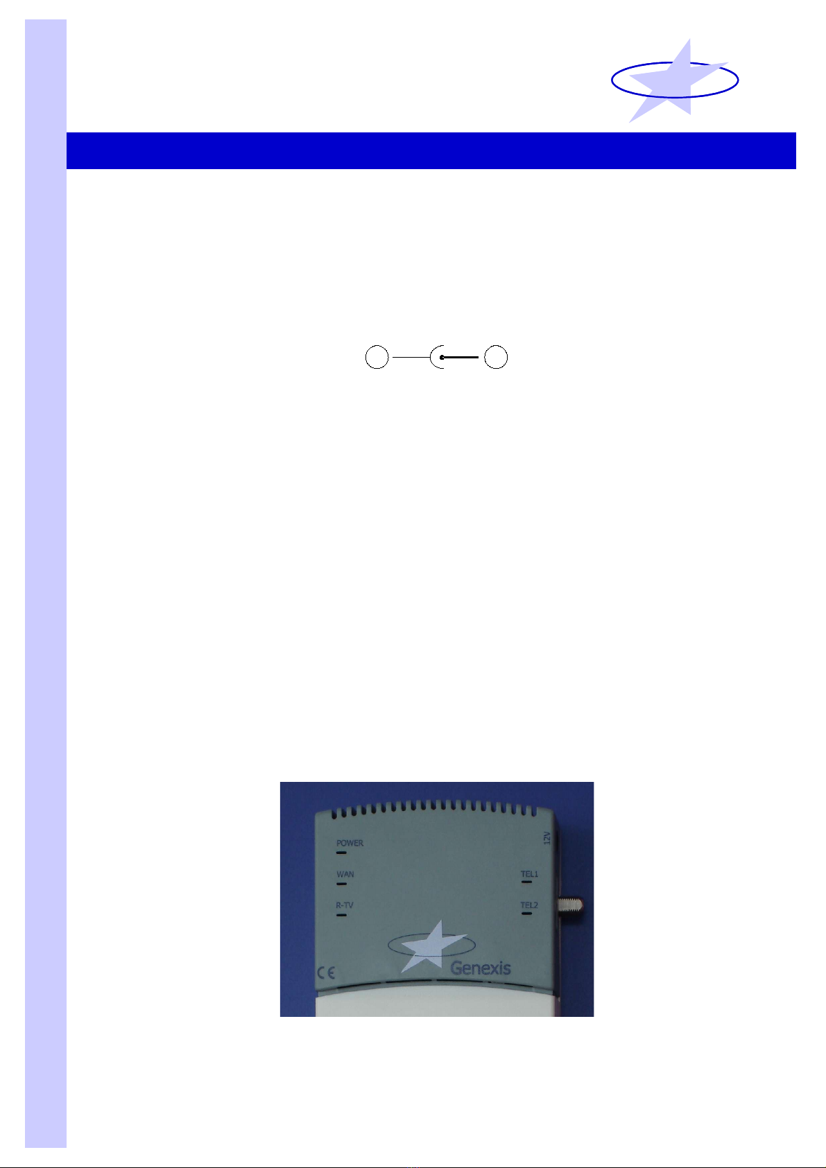
5 Activating the module
First, connect the DC-plug of the AC/DC adapter to socket at the right hand side of the
FiberXport® CG-16m module. Then connect the adapter to the 220V mains socket. The
green power LED should light up to indicate proper operation of the module power supply.
Nov 2005, Genexis B.V., Lodewijkstraat 1A, 5652 AC Eindhoven, The Netherlands, www.genexis.nl
GenexisGenexis
Press out
covering plate

The yellow WAN-port LED will light up to indicate that an appropriate optical signal is present
on the fiber carrying the optical ethernet signal. In case the optical CATV receiver is installed
and connected the yellow RTV-port LED will light up as well.
6 Closing the module
Close the module by (re)placing the white cover onto the baseplate following the installation
instructions for the housing.
Figure 2 Figure 3
Mounting of CATV module Mounting of CG-16m data/voice module
Figure 4
Detail of fixation CG-16m data/voice module
Nov 2005, Genexis B.V., Lodewijkstraat 1A, 5652 AC Eindhoven, The Netherlands, www.genexis.nl
GenexisGenexis
CG-16m fixation pin
Right hand
fiber guiding stub
CG-16m
fixation pin
hole
Fiber
guiding
stubs
Cover
screw
hole
Sliding
guides

5 Powering the module
An AC/DC adapter is provided with each CG-16m module with the following specifications:
•AC input voltage range: 90 - 264 V-AC
•AC input frequency: 47 - 63 Hz
•DC output voltage: nominal 12V-DC, max 14.4 V-DC
•DC output current: min. 1.25 A
The connection scheme of the DC-plug is indicated in Figure 5.
Figure 5
DC plug connection scheme
6 Overview of LED performance monitors
The CG-16m module is equipped with a variety of LED indicators, as shown in Figure 6,
providing the user with an efficient tool to check the correct operation of the CG-16m:
•Power LED (top-left):
This LED lights up green to indicate that the AC/DC adapter is connected correctly.
•WAN LED (middle-left):
This LED lights up yellow when the optical input power at the WAN port is within
specification to indicate a good fiber connection to the Central ffice.
•RTV LED (bottom-left):
This LED will light up yellow to indicate that a CATV signal is present (in case an CG-
12m CATV receiver is present).
•Tel1 LED (middle-right):
This LED will light up yellow to indicate when telephone line 1 is registered; during a
firmware upgrade this LED will flash.
•Tel2 LED (bottom-right):
This LED will light up yellow to indicate when telephone line 2 is registered; during a
firmware upgrade this LED will flash.
Figure 6
CG-16m LED indicators
Nov 2005, Genexis B.V., Lodewijkstraat 1A, 5652 AC Eindhoven, The Netherlands, www.genexis.nl
GenexisGenexis
-+
-+

7 Connecting external equipment to the module
Telephone RJ-11 ports
n right hand side of the CG-16m there are 2 separate RJ-11 ports, to which standard
telephone sets can be connected. The RJ-11 ports are numbered 1 and 2 as shown in Figure 7.
Please note that an RJ-11 port is only available to the end-user when the respective telephone
line (1 or 2 or both) has been registered.
Ethernet RJ-45 ports
The CG-16m is equipped with 4 RJ-45 10/100 Mbit/s ethernet ports to which external
equipment can be connected. The RJ-45 ports are numbered 1 to 4 as shown in Figure 7.
There are 2 LED-indicators on each RJ-45 port, helping to end-user to monitor the correct
functioning of the port and the connection to the external equipment. The green LED lights up
when the RJ-45 port is connected to external equipment with active RJ-45 port and the yellow
lights up when there is activity on ethernet link between the CG-16m module and the external
equipment.
Figure 7
RJ-11 and RJ-45 port numbering
Nov 2005, Genexis B.V., Lodewijkstraat 1A, 5652 AC Eindhoven, The Netherlands, www.genexis.nl
GenexisGenexis
Tel port 1
Tel port 2
RJ-45 port 4 RJ-45 port 1
This manual suits for next models
1
Table of contents