6
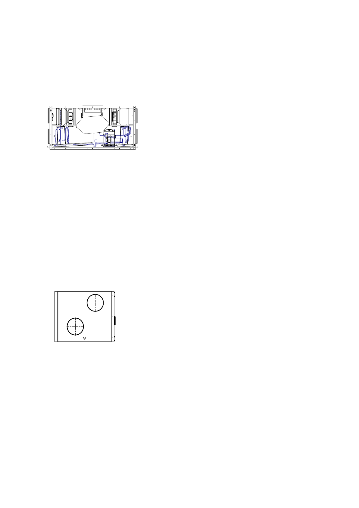
Friskluft
Afkast
Udsugning
Indblæsning
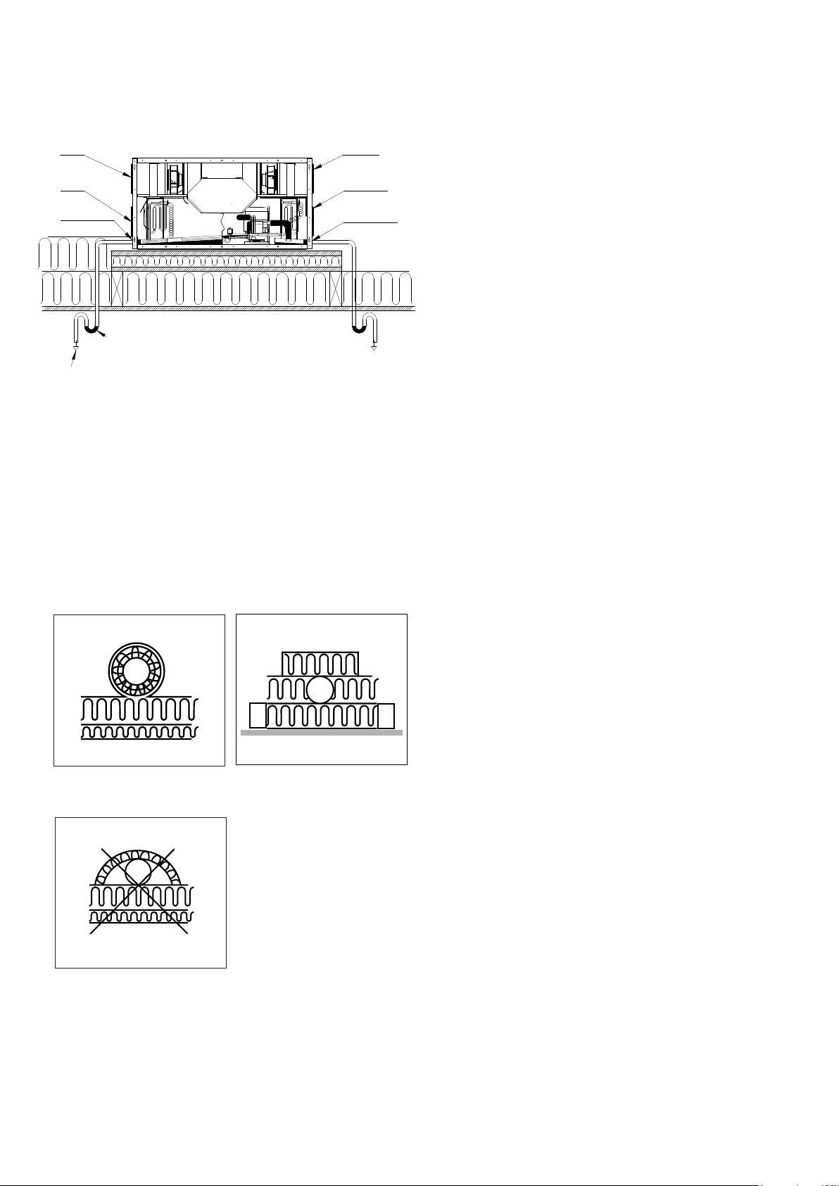
Lufttæt samling
100 mm
Lufttæt samling
No water in the water traps:
- drain clogged
- negative pressure resulting in false air
Condensation drain
The units can give o 5-8 litres of condensation in a day.
Therefore, it is important that the condensation drains
have been carried out correctly.
The condensation drain pipes must be mounted with the
necessary gradient from the condensation connections
on the unit and to the internal drain.
On each condensation drain pipe a water trap must be
tted, because there is negative pressure in the chamber
where the condensation tray is installed.
If the unit is mounted in a cold attic, the condensation
drain pipes must be insulated so that the condensation in
the pipes does not freeze up.
However, it is recommended that the water traps are
installed
in a heated space to ensure that the water in the water
traps does not freeze.
If installation problems make it impossible to secure the
condensate drain pipe from freezing using insulation,
it will be necessary to mount a thermostat-controlled
heating coil around the condensate drain pipes.
In connection with checking and replacing lters, it is
recommended that the water traps are checked and then
lled with water if necessary.
Insulation of ducts in cold attics
In order to benet from the unit‘s high heat recovery rate, it
is necessary that the ducts are insulated properly.
Genvex recommends the following:
Supply air and extract air ducts:
In order to minimise the loss of heat from the duct system
in cold attics, the supply air and extract air ducts must be
insulated with a minimum of 100 mm insulation.
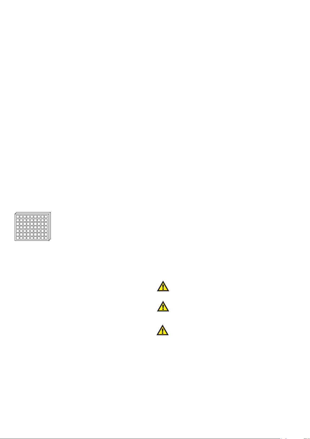
If insulation type A is chosen, it is recommended that
insulating is done with two layers of 50 mm lamella mat
nished o with paper or foil on the outside and that the
joints between the two insulation layers are staggered.
If the ducts are positioned on the rafter foots, then type
B can be used. The insulation must always be tightly
wrapped around the ducts, especially on fresh air and
exhaust air ducts in cold rooms.
Fresh air and exhaust air ducts:
It is recommended that fresh air and escape air ducts are
insulated with a minimum of 50 mm insulation. The fresh air
duct is insulated to prevent warm air in the attic heating up
the fresh air during the summer.
Make sure to seal tightly, especially where the ducts are
led through the roof or out through gables in order to avoid
condensation damage.
Contact your local supplier for instructions about national
guidelines concerning insulation.
Premium Preheat range
Isolering af kanaler, alt. A
Isolering af kanaler, alt. B
Forkert isolering af kanaler