Gima DIATERMO 106 User manual

MANUALE D’ISTRUZIONI / INSTRUCTION’S MANUAL /
MANUAL DE INSTRUCCIONES
DIATERMO 106
MA126IGBEa

MA126IGBEa Ed.01-2006

DIATERMO 106 GIMA SpA
Manuale d’istruzioni / Instruction’s Manual / Manual de Instrucciones MA126IGBEa 3
IMPORTANTE / IMPORTANT / IMPORTANTE
Queste istruzioni operative costituiscono una parte fondamentale dell’apparecchiatura per chirurgia ad
alta frequenza, in quanto ne descrivono il funzionamento e l’uso, pertanto devono essere lette
attentamente prima di iniziare l’installazione e l’uso dell’apparecchiatura.
Tutte le istruzioni di sicurezza o note di avvertimento devono essere osservate. Siate certi che queste
istruzioni operative siano fornite insieme all’apparecchiatura quando è trasferita ad altro personale
operativo.
Nessuna parte di questo documento può essere fotocopiata, riprodotta o tradotta in un'altra lingua senza il
consenso scritto della LED SpA.
In caso di necessità di Assistenza Tecnica, contattare il proprio rivenditore.
These operating instructions form an integral part of the equipment and must be available to the
operating personnel at all times.
All the safety instructions and advice notes are to be observed. Be sure that these operating instructions
is furnished together the equipment when this is transferred to other operating people.
No part of this document could be photocopied, reproduced or translated in other language without the
written consent of LED SpA.
In case of necessity of technical assistance contact your own retailer.
Las presentes instrucciones operativas forman parte indisoluble del equipo y han de estar a disposición
del personal que lo utiliza, en todo momento.
Todas las instrucciones de seguridad y las notas de advertencia se han de cumplir al pie de la letra.
Cerciórese de que estas instrucciones operativas se adjunten al aparato, si el mismo es utilizado por otros
miembros del personal operativo.
Queda terminantemente prohibida la reproducción del presente Manual, mediante fotocopia u otros
medios, así como su traducción a otros idiomas, sin la autorización previa y por escrito.
De necesitar asistencia técnica, contacte a su revendedor.
Produttore / Manufacturer
LED SpA
PROGETTAZIONI E PRODUZIONI ELETTRONICHE
Via Selciatella, 40 04010 APRILIA (LT) ITALIA

GIMA SpA DIATERMO 106
4 MA126IGBEa Manuale d’istruzioni / Instruction’s Manual / Manual de Instrucciones
INDICE / INDEX
IMPORTANTE / IMPORTANT / IMPORTANTE.......................................................3
INDICE / INDEX............................................................................................................4
1. INTRODUZIONE......................................................................................................6
1.1 CONTROLLO LISTA PARTI .................................................................................................................... 6
1.2 DESCRIZIONE GENERALE.................................................................................................................... 6
1.3 TAGLIO MONOPOLARE........................................................................................................................ 6
1.4 COAGULAZIONE MONOPOLARE .......................................................................................................... 7
2. SICUREZZA ..............................................................................................................8
2.1 GENERALE.......................................................................................................................................... 8
2.2 INSTALLAZIONE................................................................................................................................... 9
2.3 STANDARD DI SICUREZZA APPLICABILI................................................................................................ 9
3. INSTALLAZIONE ..................................................................................................10
4. CONNETTORI E CONTROLLI............................................................................11
4.1 TARGA SUL PANNELLO POSTERIORE .................................................................................................. 11
4.1.1 Dati Identificativi del Distributore....................................................................................... 11
4.1.2 Dati Tecnici .......................................................................................................................... 11
4.1.3 Significato dei Simboli Grafici............................................................................................. 11
4.2 PANNELLO POSTERIORE.................................................................................................................... 11
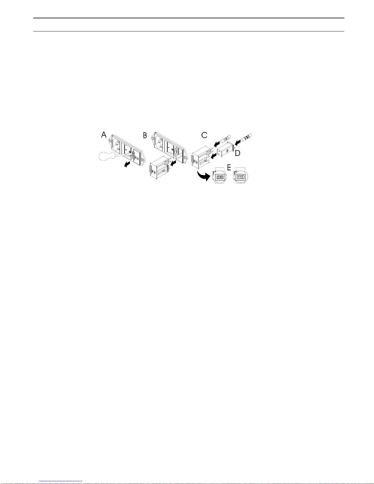
4.2.1 Modulo di Alimentazione della Apparecchiatura e Selettore di Tensione.......................... 11
4.2.2 Interruttore di Alimentazione............................................................................................... 12
4.3 PANNELLO FRONTALE....................................................................................................................... 12
4.3.1 Pulsanti d'uso........................................................................................................................ 12
4.3.2 Connettori............................................................................................................................. 13
4.3.3 Indicatori di avvertimento.................................................................................................... 13
5. CARATTERISTICHE TECNICHE.......................................................................14
5.1 GENERALI......................................................................................................................................... 14
6. MANUTENZIONE..................................................................................................15
6.1 GENERALITÀ..................................................................................................................................... 15
6.2 PULIZIA DEL CONTENITORE .............................................................................................................. 15
6.3 PULIZIA E STERILIZZAZIONE DEGLI ACCESSORI ................................................................................. 15
6.4 CONTROLLO DELL'APPARECCHIATURA PRIMA DELL'USO................................................................... 15
6.5 CONTROLLO E MISURA DI FUNZIONI DI SICUREZZA............................................................................ 15
* * * * * * * * * * * * * * * * * * * * * * * * * * * * * * * * * * * * * * * * * * * * * * *
1. INTRODUCTION....................................................................................................17
1.1 CHECK-LIST...................................................................................................................................... 17
1.2 GENERAL DESCRIPTION.................................................................................................................... 17
1.3 MONOPOLAR CUTTING ..................................................................................................................... 17
1.4 MONOPOLAR COAGULATION ............................................................................................................ 18
2. SAFETY....................................................................................................................19
2.1 GENERAL.......................................................................................................................................... 19
2.2 INSTALLATION.............................................................................................................................. 20
2.3 APPLICABLE SAFETY STANDARDS............................................................................................ 20
3. INSTALLATION.....................................................................................................21
4. CONNECTORS AND CONTROLS.......................................................................22
4.1 LABEL ON THE REAR PANEL ...................................................................................................... 22
4.1.1 Dealer's Identification Data................................................................................................. 22
4.1.2. Technical Data .................................................................................................................... 22
4.1.3 Graphic Symbols' Meaning.................................................................................................. 22
4.2 REAR PANEL.................................................................................................................................. 22
4.2.1 Equipment Mains Input Module and Voltage Selector........................................................ 23
4.2.2 Power On-Off Switch............................................................................................................ 23
4.3 FRONT PANEL............................................................................................................................... 23
4.3.1 User Keys.............................................................................................................................. 23
4.3.2 Connector ............................................................................................................................. 24

DIATERMO 106 GIMA SpA
Manuale d’istruzioni / Instruction’s Manual / Manual de Instrucciones MA126IGBEa 5
4.3.3 Warning Signals ................................................................................................................... 24
5. TECHNICAL SPECIFICATIONS.........................................................................25
5.1 GENERAL....................................................................................................................................... 25
6. PREVENTIVE MAINTENANCE..........................................................................26
6.1 GENERAL....................................................................................................................................... 26
6.2 CLEANING OF THE CABINET ..................................................................................................... 26
6.3 CLEANING AND STERILIZATIONOF THE ACCESSORY ITEMS............................................... 26
6.4 CHECKING OF THE EQUIPMENT BEFORE EACH USE .......................................................... 26
6.5 FUNCTION AND SAFETY CHECK AND TEST ............................................................................ 26
* * * * * * * * * * * * * * * * * * * * * * * * * * * * * * * * * * * * * * * * * * * * * * *
1. INTRODUCCIÓN....................................................................................................27
1.1 CONTROL DE LA LISTA DE PARTES .................................................................................................... 27
1.2 DESCRIPCIÓN GENERAL ................................................................................................................... 27
1.3 CORTE MONOPOLAR......................................................................................................................... 27
1.4 COAGULACIÓN MONOPOLAR............................................................................................................ 28
2. SEGURIDAD............................................................................................................29
2.1 CARACTERÍSTICAS GENERALES.......................................................................................................... 29
2.2 INSTALACIÓN .................................................................................................................................... 30
3. INSTALACIÓN........................................................................................................31
4. CONECTORES Y CONTROLES..........................................................................32
4.1 PLACA DEL PANEL TRASERO.............................................................................................................. 32
4.1.1 Datos de identificación del Fabricante................................................................................ 32
4.1.2 Datos Técnicos ..................................................................................................................... 32
4.1.3 Significado de los Símbolos Gráficos................................................................................... 32
4.2 PANEL TRASERO ............................................................................................................................... 32
4.2.1 Módulo de alimentación del aparato y selector de tensión................................................. 33
4.2.2 Interruptor mecánico de la alimentación............................................................................. 33
4.3 PANEL FRONTAL............................................................................................................................... 33
4.3.1 Botones de uso...................................................................................................................... 33
4.3.2 Conectores........................................................................................................................... 34
4.3.3 Señales luminosas de advertencia........................................................................................ 34
5. CARACTERÍSTICAS TÉCNICAS........................................................................35
5.1 Características generales........................................................................................................ 35
6. MANTENIMIENTO................................................................................................36
6.1 CARACTERÍSTICAS GENERALES.......................................................................................................... 36
6.2 LIMPIEZA DE LA CARCASA ................................................................................................................. 36
6.3 LIMPIEZA Y ESTERILIZACIÓN DE LOS ACCESORIOS ............................................................................. 36
6.4 CONTROL DEL APARATO ANTES DE USARLO....................................................................................... 36
6.5 CONTROL Y MEDIDAS DE FUNCIONES DE SEGURIDAD........................................................................ 36
OUTPUT POWER DIAGRAMS................................................................................37

DIATERMO 106 GIMA SpA
Manuale d’istruzioni / Instruction’s Manual / Manual de Instrucciones MA126IGBEa 17
1. INTRODUCTION
1.1 CHECK-LIST
Check that all the items and accessories which had been ordered have been delivered, according to the
following list:
Ref.Nr.GMA10100.05A DIATERMO 106 Unit
Ref.Nr. 00100.03 Unit mains cable 2 meters long
Ref.Nr. 00404.08 Cable for connection of the reference electrode
Ref.Nr. 5365 Reference electrode
Ref. Nr. 00301.00 Pedal switch
Ref. Nr. 00500.03 Kit of 6 assorted tip
Ref. Nr. MA126IGBE Instruction's Manual
1.2 GENERAL DESCRIPTION
DIATERMO 106, High Frequency Surgical Equipment, provides the facility to carry out monopolar
minor surgery.
The equipment is designed for desk-top use.
The most advanced electronic components and circuitry including LSI microcontrollers are applied to
provide all the prerequisite for safe and reliable operation.
In this way most of the thermic problems, and the need for cooling fans, very dangerous for the batterium
diffusion in the health care rooms, have been overcome.
Control of the unit is via the front panel keys and display; mains inlet and on/off switch are on the rear
panel.
The type of surgical operation which can be carried out are those where monopolar minor electrosurgical
cutting or coagulation is requested.
Use of DIATERMO 106 is restricted to trained medical personnel, and it is to be used only for the
purposes set down by the manufacturer.
DIATERMO 106 consists of the following components:
the generator, or unit
the handpiece
the electrodes
the dispersive plate
the pedal switch
1.3 MONOPOLAR CUTTING
Monopolar cutting is the sectioning of the biological tissue caused by the passing of high density, high
frequency current concentrated by the tip of the active electrode. When the high frequency current, by
the tip of the active electrode, is applied to the tissue, it creates intense molecular heat in the cell so that
the cell explodes. The cutting effect is achieved by moving the electrode through the tissue and
destroying the cell one after the other. The movement of the electrode prevents the propagation of the
heat laterally in the tissue, thus limiting the destruction to a single line of cells.
The best current for cutting is pure sine wave without any modulation which cuts very smoothly and
provides the least thermal effect with poor hemostasis while cutting. Because its effects can be precisely
controlled, it can be used safely without damage to the bone, but since good coagulation while cutting is
one of principal benefits of using electrosurgery a current with a certain amount of modulation is
desirable.
DIATERMO 106 allows cutting with pure sine wave form as well as with two degrees of moderate
modulation producing blend wave form with different crest-factor, so more hemostatic effect than with
pure sine wave form is achieved.

GIMA SpA DIATERMO 106
18 MA126IGBEa Manuale d’istruzioni / Instruction’s Manual / Manual de Instrucciones
The following rules help the operator to obtain good cutting, however every user must follow first of all
his professional judgement as he does every time in his practice.
Keep the tissues moist but not wet
Survey the stroke before activate the electrode
Keep the electrode perpendicular to the tissue
Activate the electrode before making contact with the tissue
Keep the electrode clean
Wait at least five seconds before to repeat a stroke.
When the output power is properly set there should be:
no resistance to the electrode movement through the tissue
no change in the cut surfaces color
no fibers of tissue remained onto the electrode
1.4 MONOPOLAR COAGULATION
Monopolar coagulation is the hemostasis of small blood vessel of the bodily tissue through the passing of
high frequency current in correspondence of the active electrode.When the current density is reduced and
a broad-surfaced electrode is used to dissipate the energy over a larger area, the effect is to dry out the
surface cells, without deep penetration, resulting in coagulation. These coagulate surface cells then serve
as a layer of insulation, preventing heat from successive applications of current from penetrating too
deeply.
The current normally used for coagulation is modulated and depending from the modulation percentage
is the smoothness of cutting, goodness of hemostasis and likelihood of tissue destruction. Deeper current
modulation brings to somewhat roughly cutting and the chance of some slight depth of tissue destruction
but more efficient coagulation.
DIATERMO 106 allows coagulation with deep modulation producing blend wave form with high crest-
factor so more thermal effect and consequently hemostatic effect than with pure sine current has
achieved.
The following rules help the operator to obtain good coagulation: however every user must follow first
of all his professional judgement as he does every time in his practice.
Select a ball or heavy wire electrode
Locate the bleeder, after have wiped the excess blood from the area, contact lightly the bleeder
before activating the electrode
Stop the electrode activation as soon as the tissue blanches to avoid tissue damage.

DIATERMO 106 GIMA SpA
Manuale d’istruzioni / Instruction’s Manual / Manual de Instrucciones MA126IGBEa 19
2. SAFETY
WARNING These operating instructions form an integral part of the equipment and must be available to
the operating personnel at all times. All the safety instructions and advice notes are to be observed. Be
sure that these operating instructions is furnished together the equipment when this is transferred to
other operating people.
Electrosurgery can be dangerous. Careless use of any element in the electrosurgical system may subject
the patient to a serious burn. Read and understand all warnings, precautions, and directions for use
before attempt to use any active electrode. Neither LED S.p.A., Frosinone, Italy nor any of the subsidiary
sales organisations can be considered responsible for personal, material or consequential injury, loss or
damage that results from improper use of the equipment and accessories.
2.1 GENERAL
Persons fitted with a heart pacemaker must not operate the equipment nor approach the same while
it is in operation.
The patient does not must be in contact with metal parts that are connected to the earth or have a
large electrical coupling capacity to the earth (for example: operating-table or metallic support).
The use of antistatic sheets is advised.
Avoid the skin to skin contact (for example between arm and body of the patient). Insert an
interface material like dry surgical gauze.
When high frequency electrosurgical unit and phisiological monitoring devices are used at a time
in the same patient, all the monitoring electrodes, that has not resistive or inductive elements
suitable to high frequency interferencies, must be as far as possible from the electrodes of the
electrosurgical unit.
Avoid the use of monitoring needles.
The connection to the electrodes should be located in such a way to avoid the contact both with the
patient and with other cables.
The power level should be the lowest useful to the work to do.
Always check the dispersive plate whenever the electrosurgical unit fails to produce the desired
effect. Reason for a low output power level, or for an uncorrect functioning of the electrosurgical
unit when arranged for a normal output, may be lack of connection of the dispersive plate or its
imperfect placement.
The use of flammable anesthetics, of oxygen and of nitrogen protoxyde should be avoid in the case
of operation at the head or at chest level except the possibility of evacuating gas.
Flammable materials used to clean, or to disinfect, should be let to evaporate before the use of the
electrosurgical unit.
There is risk of stagnation of flammable solutions under the patient or in body cavities as the
umbilicus and the vagina. The fluid which deposits in these areas should be removed before the
equipment use. The danger of endogenous gas ignition has to be considered.
Some materials like cotton wool or gauze, when saturated with oxygen, may burst into flames
because of the sparks produced by the equipment in the normal use.
There is a risk for the patients fitted with heart pace-maker, or other stimulation electrode: an
interference may occur with the stimulator signal or the stimulator itself can be damaged. Please
refer to the cardiologic department when in doubt.
The use of electrosurgery is not recommended in patients:
with serious unbalance of arterial pressure
with serious illness of the nervous system
with serious renal insufficiencies
in state of pregnancy
Inadvertent stimulation of a patient's muscle and nerves can be caused by low frequency currents
originating in electric sparks between the electrode and the tissue of the patient. Should
neuromuscular stimulation occur stop the surgery and check all the connections to the generator. If
this does not solve the problem the generator must be inspected by qualified service personnel.

GIMA SpA DIATERMO 106
20 MA126IGBEa Manuale d’istruzioni / Instruction’s Manual / Manual de Instrucciones
The electrosurgical equipment does emit unnoticed radiation of high frequency energy that may
effect other medical equipments, unrelated electronics, telecommunications, navigational systems.
2.2 INSTALLATION
The electric safety of DIATERMO 106 is insured only when the same is correctly connected to an
efficient net linked to the earth in conformity with the actual safety requirements. It is neccessary
to verify this fundamental safety requisite and, in case of doubt, to require an accurate control of
the plant from part of qualified personnel. The manufacturer cannot be considered responsible for
possible damages caused from the lack of efficient connection to earth of the installation.
Operation without a protective earth connection is forbidden.
Before connect the equipment ascertain that the required voltage (showed on the rear panel)
corresponds to the available mains. The fuse holder is installed on the mains input connector
module.
In case of incompatibility between the available wall socket and the feeding cable of the
equipment, replace only with legally approved connectors and accessory items. The use of
adapters, multiple connections or cable extensions are not advised. Should their use become
necessary it is mandatory to use only simple or multiple adapter conforming to the actual safety
requirements.
The use of any electric apparatus involves the observance of some fundamental rules. Particularly:
don't touch the apparatus with wet or damp feet or hands.
don't use the apparatus with naked feet
don't let the apparatus exposed to atmospheric agents
Don't obstruct openings or cracks of ventilation or heathsink.
Don't leave the equipment uselessly inserted. Switch off the equipment when not in use.
DIATERMO 106 must be destined only to the use for the which has been expressly designed. Any
other use is to be considered improper and dangerous. The manufacturer can not be considered
responsible for possible damages due to improper, wrong and unreasonable uses.
It is dangerous to modify or try modify the characteristic of the equipment.
Before effect any operation of cleaning or maintenance, disconnect the apparatus from the electric
net, either unplugging it from the mains or switching off the mains switch of the plant.
In case failure and/or bad operation of equipment switch off it. For the possible reparation address
only to a authorized service center and ask for the the use of original spare parts. The lack to follow
the above requirements could risk the safety of the equipment and can be dangerous for the user.
Never lay the pen on the patient drape. Set it on the instrument tray when not in use. Accidental
activation can cause patient burns beneath the blade of the active electrode.
Do not reduce or disable the audible signal warning the activation of the generator. A functioning
activation signal can minimize or prevent patient or staff injiury in the event of accidental
activation.
2.3 APPLICABLE SAFETY STANDARDS
DIATERMO 106 conforms to the safety requirements of IEC 601-1/ EN 60601-1 (Medical electrical
equipment-General requirements for safety), and of IEC 601-2-2 / EN 60601-2-2 (Medical electrical
equipment - Particular requirements for the safety of high frequency surgical equipment).

DIATERMO 106 GIMA SpA
Manuale d’istruzioni / Instruction’s Manual / Manual de Instrucciones MA126IGBEa 21
3. INSTALLATION
Inspect the equipment for damage during transit. Any damage should be reported to the carrier
immediately.
Unpack the equipment and carefully study the documentation and operating instruction supplied.
The mains input voltage, indicated up the equipment mains input, must agree with the local mains
voltage (mains frequency: 50-60 Hz). The correct voltage setting is selected as shown in fig. E
Insert the correct fuses in the module according to the following table:
Mains Voltage 110-120 V Fuse 2 x 2AT (Anti-surge) Type 5 x 20 mm
Mains Voltage 220-240 V Fuse 2 x 1AT (Anti-surge) Type5 x 20 mm
To insert the fuses pull out the fuse holder from the mains module with the help of a screwdriver
(Fig.1 and Fig. 2) - clip the fuses into the holder (Fig. 3) - replace the holder into the module.
Connect the mains cable to a mains outlet that has good earth connection.
OPERATION OF THE EQUIPMENT WITHOUT EARTH CONNECTION IS FORBIDDEN
Position the equipment such that there is sufficient room around it. Air circulation must not be
restricted in any way.
Operate the equipment only in dry surroundings. Any condensation that occurs must be allowed to
evaporate before putting the equipment into operation. Do not exceed the permissible ambient
temperature or humidity.
Environmental conditions:
Temperature: from 10°C up to 40 °C
Relative moisture: from 30% up to 75%
Atmospheric pressure: from 70 kPa up to 106 kPa (10 PSI up to 15 PSI)

GIMA SpA DIATERMO 106
22 MA126IGBEa Manuale d’istruzioni / Instruction’s Manual / Manual de Instrucciones
4. CONNECTORS AND CONTROLS
4.1 LABEL ON THE REAR PANEL
The requirements for the safety of H.F. surgical equipment ask that some technical data and graphic
symbols must be printed on the cabinet or on at least one of the panels of the generator unit to define its
features and oversee its condition of work.
4.1.1 DEALER'S IDENTIFICATION DATA
The DIATERMO 106 H.F.Electrosurgical unit is dealered by GIMA SpA Via Marconi, 1 I-20060
Gessate (MI) -ITALY-
4.1.2. TECHNICAL DATA
OUTPUT COAG: 40 W – 400FREQUENCY: 600 kHz
OUTPUT CUT: 50 W - 400FREQUENCY: 600 kHz
MAIN POWER: 115 V~ - 50/60 Hz FUSE:2 x 2 AT (Antisurge)
230 V~ - 50/60 Hz FUSE:2 x 1 AT (Antisurge)
DUTY-CYCLE: intermittent 10 seconds output / 25 seconds pause.
CLASS: I CF
4.1.3 GRAPHIC SYMBOLS'MEANING.
The meaning of the graphic symbols printed on the DIATERMO 106 's cabinet is the following:
1. Floating Patient's plate: not connected to the earth neither at low-frequency nor at high frequency.
2. The equipment is protected against H.V. discharge due to the use of a Cardiac Defibrilator.
3. Not Ionizing Radiation emitted
4. Read carefully the INSTRUCTION's MANUAL before to attempt the use of the equipment.
1 2 3 4
4.2 REAR PANEL
1 - IEC MAINS INPUT CONNECTOR
2 - MAINS SWITCH
3 - FUSE HOLDER AND VOLTAGE SELECTOR

DIATERMO 106 GIMA SpA
Manuale d’istruzioni / Instruction’s Manual / Manual de Instrucciones MA126IGBEa 23
4.2.1 EQUIPMENT MAINS INPUT MODULE AND VOLTAGE SELECTOR
The equipment mains input module provides the connection point for the power of the equipment's
internal electronics. The mains input module incorporates the mains input socket, the main input voltage
selector and in-line mains fuses.
WARNING: Before the unit is powered up the operator should check that the mains input voltage
indicated on the power input module corresponds to the mains voltage supply to which it is to be
connected, and that the correct mains fuse type for the selected mains voltage has been inserted.
4.2.2 POWER ON-OFF SWITCH
POWER ON/OFF mechanical switch is used to control power to the equipment. To power the
equipment, press the switch in the direction of the 1 (i.e. right side).
When the equipment is powered the front panel will illuminate. Pressing the switch in the 0 direction
will cut power to the equipment, this operation allows the switch to be used as a emergency stop switch,
in the event of any fault.
4.3 FRONT PANEL
1 Key for output power decrease 6 COAG key
2 Output power display 7 Pen-holder connector
3 Key for output power increase 8 Patient Plate connector
4 CUT 1 key 9 Foot-switch connector
5 BLEND key
4.3.1 USER KEYS
The keys are split into two groups, the four operative keys, positioned at the left of the unit, and the two
output power control keys under the digital display.
The two output power control keys are used to increase (+) or decrease (-) the output current.
The function of each of the operative keys is as follows:
Pressing this key Cut current, i. e. pure sine current is preset, to be delivered when the foot-switch output
control is activated. Crest factor of the Cut current is 1.5. Cut current preset condition is indicated by
green LED which will illuminate.

GIMA SpA DIATERMO 106
24 MA126IGBEa Manuale d’istruzioni / Instruction’s Manual / Manual de Instrucciones
Pressing this key Blend current, i.e. modulated current is preset, to be delivered when the foot-switch
output control is activated. Crest factor of the Blend current is 1.8. Blend current preset condition is
indicated by green LED which will illuminate.
Pressing this key presets Coag current, i.e. modulated current is preset, to be delivered when the foot-
switch output control is activated. Crest factor of the monopolar Coag current is 2.5. Coag current preset
condition is indicated by green LED which will illuminate.
4.3.2 CONNECTOR
Pedal Connector
This is the connection point for the foot-switch. The pedal switch is allowed to control the output current
delivering of the operative condition.
Monopolar Patient Plate Connector
This is the connection point for the Patient Plate.
Handpiece Connector
This is the connection point for the handpiece.
4.3.3 WARNING SIGNALS
Should the unit's inside temperature rise above 75 °C i.e. the save working level, the digital display
blinks. Stop the output emission until the normal condition is restored.

DIATERMO 106 GIMA SpA
Manuale d’istruzioni / Instruction’s Manual / Manual de Instrucciones MA126IGBEa 25
5. TECHNICAL SPECIFICATIONS
5.1 GENERAL
Equipment Description:
H.F. Electrosurgery Equipment for monopolar minor surgery. The unit provides the facilities to fine
preset the output power level and choose the coagulating effect through the appropriate Crest Factor.
Cabinet:
Bench-top, metal housing, with the frontal and rear panel covered by lexan sheet.
Height: 100 mm Width: 180 mm
Depth: 180 mm Weight: 2,8 Kg
Equipment Mains Input: Selectable 115 or 230 V~, 50/60 Hz.
Maximum Current: 0,5 A (230V) or 1A (115V)
IEC socket with in-line fuses, voltage selector and mechanical mains switch.
Displays:
LED Digital Displays provide the indication of the preset output level as follows:
CUT: 0 – 50 BLEND: 0 – 45
COAG: 0 - 40
Output Power Control by two keys
The use of the control keys allows the user to control very accurately the output power since it is possible
to vary the
preset output power in step as low as just 1 watt.
Max Output Power:
CUT: 50 W +/- 10% BLEND: 45 W +/- 10%
COAG: 40 W +/- 10%
Reference Load Resistance: 400
No Load Max Voltage: 900 Vpp +/-10%
Crest Factor:
CUT: 1.5 BLEND: 1.8
COAG: 2.5
Output Frequency: 600 kHz +/- 10%
Modulation Frequency:
CUT: NONE BLEND: 10 kHz
COAG: 10 kHz
Allowed output time:
Duty Cycle: 10 seconds output-25 seconds pause

GIMA SpA DIATERMO 106
26 MA126IGBEa Manuale d’istruzioni / Instruction’s Manual / Manual de Instrucciones
6. PREVENTIVE MAINTENANCE
6.1 GENERAL
No user adjustable parts are within the equipment, either for calibration or service purposes. The
equipment housing must not be opened: the warranty is invalidated by any unauthorized entry into the
unit. In the event any repair or adjustment work being necessary, the whole equipment should be
returned to the LED S.p.A. Service Centre 04011 APRILIA (LT) - ITALY, or to a other Authorized
Centre, together with a description of the fault.
Maintenance work by the user is mainly the cleaning of the exterior of the cabinet, cleaning and
sterilization of the accessory items and checking of the equipment before each use. Carrying out function
and safety check for verification of the parameters is demanded to specialized technical people.
6.2 CLEANING OF THE CABINET
Switch the equipment off complitely and disconnect the mains supply before any cleaning is undertaken.
Clean the outside of the cabinet with a damp cloth. No chemical should be used; a mild non abrasive
cleanser may be used when necessary.
6.3 CLEANING AND STERILIZATIONOF THE ACCESSORY ITEMS
The best thing to do is to use only one time use accessories and discard them after use. Since some of the
accessory items are to be used more than once it is mandatory to clean carefully and sterilize those
accessories before the new use. The best way to clean and sterilize the reusable items is to follow the
direction of the supplier of each item. When original reusable accessories supplied by LED S.p.A. are
applied, the cleaning by using soft cleanser and sterilization through steam sterilization at 134 °C is
recommended.
6.4 CHECKING OF THE EQUIPMENT BEFORE EACH USE
Each time the use of the electrosurgical equipment is planned a check of the most important safety
aspects has to be implemented considering at least the following:
Check the integrity of cords, connections, wire breakage, etc.
Assure that all the electrical equipment is properly grounded
Assure that all the accessories that should be used are available and sterilized.
6.5 FUNCTION AND SAFETY CHECK AND TEST
At least once a year, the following check and test should be done by the biomedical engineering
department or other qualified personnel:
Check of the connectors and mains supply cord conditions;
Visual check of the mechanical protections;
Check of the protections against the danger due to liquid's pouring, dripping, moisture, liquid's
penetration, cleanliness, sterilization and disinfection.
Check of the Equipment's Datas on the Label
Check of the availability of the Instruction's Manual
Check the functioning of the H.F. output controls
Check the uniformity of the resistance through the surface of the patient plate.
Test the earth conductivity resistance.
Test the earth leakage current. Test H.F. leakage current.
Control of the neuromuscular stimulation. Control of the accuracy of the output power.

DIATERMO 106 GIMA SpA
Manuale d’istruzioni / Instruction’s Manual / Manual de Instrucciones MA126IGBEa 37
OUTPUT POWER DIAGRAMS
Diagramma valori a metà potenza / Half power
diagram
0
10
20
30
50
200
400
600
800
1000
2000
Ohm
Watt
CUT0
CUT1
COAG
Diagramma valori alla potenza massima / Max
power diagram
0
20
40
60
50
200
400
600
800
1000
2000
Ohm
Watt
CUT0
CUT1
COAG
Dia
g
ramma linearità CUT / CUT linearit
y
diagram
0
5
10
15
20
25
30
35
40
45
50
55
5 102030404550
Potenza indicata / Diplay Power (W)
Potenza in uscita /
Output power (W)

GIMA SpA DIATERMO 106
38 MA126IGBEa Manuale d’istruzioni / Instruction’s Manual / Manual de Instrucciones
Diagramma linearità BLEND / BLEND
linearity diagram
0
5
10
15
20
25
30
35
40
45
50
55
5 102030404550
Potenza indicata / Display power (W)
Potenza in uscita /
Output power (W)
Diagramma linearità COAG / COAG
linearity diagram
0
5
10
15
20
25
30
35
40
45
5 102030404550
Potenza indicata / Display power (W)
Potenza in uscita /
Output power (W)
Informazioni in base all’Art. 13 del D.Lgs. 151/05 del 25/07/2005 “Attuazione delle Direttive 2002/95/CE e 2003/108/CE, relative
alla riduzione di sostanze pericolose nelle apparecchiature elettriche ed elettroniche, nonché allo smaltimento dei rifiuti.
A fine vita il presente prodotto non deve essere smaltito come rifiuto urbano, lo stesso deve essere oggetto di
una raccolta separata.
Se il rifiuto viene smaltito in modo non idoneo è possibile che alcune parti del prodotto (ad esempio eventuali
accumulatori) possono avere effetti potenzialmente negativi per l’ambiente e sulla salute umana.
Il simbolo a lato (contenitore di spazzatura su ruote barrato) indica che il prodotto non deve essere gettato nei
contenitori per i rifiuti urbani ma deve essere smaltito con una raccolta separata.
In caso di smaltimento abusivo di questo prodotto sono previste delle sanzioni.
Information about elimination of this product (Applicable in the European Union and other European countries
with separate collection systems)
On the end of the life, the present product mustn’t be eliminated as urban refusal, but it must be eliminated in
a separated collection.
If the product is eliminated in unsuitable way, it is possible that some parts of the product (for example some
accumulators) could be negative for the environment and for the human health.
The symbol on the side (barred dustbin on wheel) denotes that the products mustn’t throw into urban refuses
container but it must be eliminated with separate collection.
In case of abusive elimination of this product, could be foreseen sanctions.
Información sobre la eliminación de este producto (Aplicable en le Unión Europea y en países europeos con
sistemas de recogida selectiva de residuos)
En el final de la vida, el actual producto no se debe eliminar como denegación urbana, sino que debe ser
eliminado en una colección separada.
Si el producto se elimina de manera inadecuada, es posible que algunas partes del producto (por ejemplo
algunos acumuladores) podrían ser negativas para el ambiente y para la salud humana.
Este símbolo indica que el presente producto no puede ser tratado como residuos domésticos normales, sino
que deben entregarse en el correspondiente punto de recogida de equipos eléctricos y electrónicos.
En caso de que de eliminación abusiva de este producto, podrían estar las sanciones previstas.
Table of contents
Popular Hot Tub manuals by other brands

Calspas
Calspas 2006 Portable spas owner's manual

Daybreak Fitness
Daybreak Fitness Daybreak 860 WLHS86090 user manual

Waterway
Waterway 600-9101 operating instructions

Strong Pools and Spas
Strong Pools and Spas St. Martin owner's manual

Aquatic
Aquatic LUXEAIR 26 ai26lux7242 Specification sheet

Aquatic
Aquatic LUXEAIR 29 ai29lux6038 Specification sheet