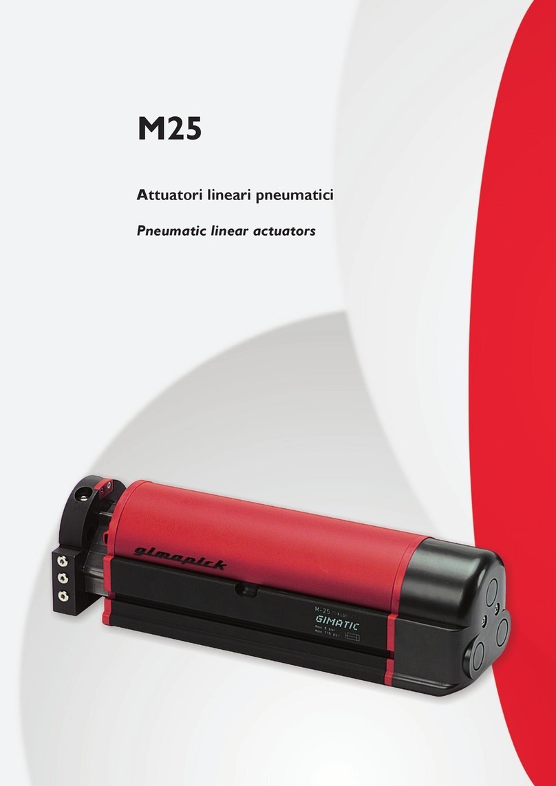
Gimatic LV SERIES User manual

ELECTRIC LINEAR ACTUATORS
LV SERIES
USER GUIDE
Version 2.1

Page intentionally left blank

TABLE OF CONTENTS
1. SAFETY - General prod ct safety information
1.1.General safety
2. INTRODUCTION - Introd ction to this ser g ide
2.1.Abo t this ser g ide
2.2.Terms and abbreviations
3. PRODUCT OVERVIEW - Abo t Gimatic's prod cts: feat res and catalog e n mber interpretation
3.1.Abo t Gimatic's LV Act ators
3.2.Feat res
3.3.LV and LVP systems
3.4.LV prod ct range
3.5.Catalog e n mber interpretation
4. SYSTEM DESIGN - How to design a LV based system for yo r application
4.1.System components
4.2.Electric linear slides
4.2.1.Application
4.2.2.Slider
4.2.3.Stator
4.2.4.Weight co nter balance
4.2.5.Brake
4.2.6. Cable carrier
4.3.Servo drive
4.4.Linear encoder
4.5.Sensors
5. SPECIFICATIONS - Overall characteristics of LV linear slide
5.1.Electrical
5.2.Operative fields
5.3.Static thr sts
5.4.Mechanical
5.5.Safety loads
5.6.Deflection
6. INSTALLATION - Mechanical and electrical config ration
6.1.Unpacking
6.2.Mechanical
6.2.1.Linear encoder
6.2.2. Mo nting examples
6.3.Electrical
6.3.1.Motor power and temperat re feedback
6.3.2.Sensors
6.3.3.Electromagnetic compatibility (EMC)

6.4.Servo drive config ration
7. MAINTENANCE - S ggested activities for systems based on Gimatic's LV prod cts
8. ACCESSORIES - Available accessories
9. APPENDIX - Additional information
9.1.Application contin o s force calc lation example
9.2.D ty cycle calc lation
10. SERVICE ENQUIRIES - Information req ired for a correct enq iry
10.1. Main Application Data

Gimatic
-
LV Electric Linear Act ators
www.gimatic.com
Page
1
1. SAFETY
This man al and the warnings attached to the LV linear slides only highlight hazards that can be predicted
by Gimatic. Be aware they do not cover all possible hazards.
Gimatic shall not be responsible for any accidents ca sed by the mis se or ab se of the device by the
operator.
Safe operation of these devices is yo r own responsibility. By taking note of the safety preca tions, tips and
warnings in this man al, yo can help to ens re yo r own safety and the safety of those aro nd yo .
WARNIN
: Embedded t b lar motor shafts contain powerf l permanent magnets.
People with pacemakers, AICD or similar medical devices sho ld maintain a
minim m distance of 30 cm from the shaft.
DAN ER HI
H VOLTA E
: Ens re the power has been completely disconnected
before to ching any electrical connections. Electrical shock can ca se serio s or
fatal inj ry.
DAN ER HI H VOLTA E
: The system m st be properly gro nded before applying
power. Ens re the system has been gro nded according to Section 6.3.1 Motor
power and temperature feedback. National and local electrical codes m st be
followed. Electrical shock can ca se serio s or fatal inj ry.
WARNIN
: The shaft emits a very strong magnetic field. Always se ca tion when
handling. To avoid inj ry, keep fingers and other body parts clear.
WARNIN
: When embedded temperat re sensor (PTC) is employed a t
emperat re
val e of 95 °C m st be set as maxim m temperat re allowed for the stator d ring
driver’s programming. This is eq ivalent to the PTC val e less or eq al to 1330 Ω
(Section 4.5 Sensors). Whenever PTC connection is not possible a proper i2t
parameter has to be set by the ser d ring driver’s programming in order to
preserve ML stator from permanent damaging.

Gimatic
-
LV Electric Linear Act ators
www.gimatic.com
Page
2
1.1 eneral safety
The following points m st be nderstood and adhered to at all times:
•Eq ipment operators m st read the User G ide caref lly and make s re of the correct proced re
before operating the LV linear act ators.
•Memorize the locations of the power and drive isolator switches so that yo can activate them
immediately at any time if req ired.
•If two or more people are working together, establish signals so that they can comm nicate to
confirm safety before proceeding to another step.
•Be aware of the closest First Aid station.
•Always make s re there are no obstacles or people near the devices d ring installation and or
operation. Be aware of yo r environment and yo r s rro ndings.
•Keep the area aro nd LV act ators clean and tidy.
•Take preca tions to ens re that yo r clothing, hair or personal effects (s ch as jewelry) cannot
become entangled in the eq ipment.
•Do not t rn on any of the eq ipment witho t all safety feat res in place and known to be
f nctioning correctly. Never remove any covers or g ards nless instr cted by the proced res
described in this man al.
•Never to ch any exposed wiring, connections or fittings while the eq ipment is in operation.
•Vis ally check all switches on the operator panel before operating them.
•Do not apply any mechanical force to the LV act ators, which may ca se malf nction or fail re.
•Never attempt cleaning or inspection when the machine is operating.
•Clean or inspect the eq ipment only after isolating all power so rces.
•Only s itably q alified personnel sho ld install, operate, repair and/or replace this eq ipment.
•Ens re all external wiring is clearly labeled. This will assist yo and yo r colleag es in identifying
possible electrical safety hazards.
•Use cables with the minim m cross sectional area as specified in the Electrical Connection
specification section of this g ide.
•Install cables according to local legislation and reg lations as applicable.
•Ens re there are not moving parts of the act ator while in contact with the motor’s electrical
connections. Movement can ind ce a voltage that co ld ca se an electrical shock.

Gimatic
-
LV Electric Linear Act ators
www.gimatic.com
Page
3
2 INTRODUCTION
2.1 About this user guide
This ser g ide provides the req ired information for planning to install, installation and servicing of the LV
linear slides. It has been written specifically to meet the needs of q alified engineers, tradespersons,
technicians and operators.
2.2 Terms and abbreviations
GND
Gro nd
rms
Root mean sq are
g
Gravity m/s
2
V / mV
Volt / millivolt
A / mA
Ampere / milliampere
Ω
ohms
AC / DC
Alternating C rrent / Direct C rrent
Hz
Hertz
ms
millisecond
AICD
A tomatic Implantable Cardioverter
-
Defibrillator
EMC
Electromagnetic Compatibility
3 PRODUCT OVERVIEW
3.1 About imatic's LV actuators
The Gimatic LV act ator is a recirc lating ball bearing slide eq ipped with a 3-phase, br shless, DC,
permanent-magnet motor designed for direct-drive, high-precision and high-dynamics applications. High
efficiency and performance of Gimatic's ML linear motors meet a lightweight al mini m slide which
provides a prismatic g ide for the motion of the slider (anti-rotation), a heat dissipation f nctionality and
high stiffness in several directions. Adj stable preloading screws and long life bearings ass re low
installation and maintenance costs.

Gimatic
-
LV Electric Linear Act ators
www.gimatic.com
Page
4
3.2 Features
•High contin ative force/c rrent.
•Zero backlash – No ball screw or gearbox eliminates backlash.
•High acceleration forces – More than 400 [N] depending on model.
•Low installation and maintenance costs – Simple constr ction, T-n t grooves for fastening.
•F lly sealed – IP67 rating standard.
•Zero net attractive forces improve efficiency with no down force and extended machine life.
•D rable – Stator materials’ high ins lation class res lts in long motor life. 10 million cycles
maintenance-free.
•Efficient – The extremely strong magnetic fl x, cylindrical design and small moving mass provide for
very efficient linear motion.
3.3 LV and LVP systems
LV act ators can be combined in order to create m ltiple axis systems. F rthermore for all those
applications req iring longer strokes and/or higher stiffness along the entire stroke, Gimatic linear
act ators are also available as linear g ides (LVP25 and LVP40). These g ides can be combined with LV
act ators to create more complex str ct res (i.e. cartesian manip lators).
LV EXAMPLE APPLICATION: 2 AXIS PICK&PLACE SYSTEM
LVP SYSTEM STRUCTURE
Y
Z
LVP25
act ator
Magnetic
slider
Linear
motor
En
coder
Adj stment
screws
T
-
n t grooves
for fastening
Hardened
steel bars
M12
connection

Gimatic
-
LV Electric Linear Act ators
www.gimatic.com
Page
5
LVP+LV EXAMPLE APPLICATION: 3 AXIS PICK&PLACE SYSTEM
3.4 LV product range
LV25050
LV25100
LV25150
LV25
200
LV40050
LV40100
LV40150
LV40200
Stroke [mm]
50
100
150
200
50
100
150
200
Total mass [g]
1170
1380
1825
2185
2730
3590
4430
4865
Mass of parts
fixed to the
slider [g]
560 670 850 1050 1350 1840 2150 2420
BUS voltage
[Vdc] (peak) 72 325 72 325 72 325 72 325 72 325 72 325 72 325 72 325
Peak c rrent
[A] 7.87 3.49 7.87 3.49 5.42 2.07 5.42 2.07 19.85 8.79 19.85 8.79 15.46 6.19 15.46 6.19
Contin ative
c rrent [A] 1.57 0.49 1.57 0.49 1.48 0.48 1.48 0.48 3.09 0.94 3.09 0.94 3.38 0.98 3.38 0.98
Peak force
[N] 100 120 100 120 110 130 110 130 270 420 270 420 320 440 320 440
Contin ative
force [N] 20 17 20 17 30 30 30 30 42 45 42 45 70 70 70 70
X
Y
Z

Gimatic
-
LV Electric Linear Act ators
www.gimatic.com
Page
6
3.5 Catalogue number interpretation
Electric linear slide: ordering code example
LV25050-70ABZHALL
Motor's size: 25 [mm]
40 [mm]
Stroke: 050 [mm]
100 [mm]
150 [mm]
200 [mm]
BUS voltage: 70 (72 [V] peak)
300 (325 [V] peak)
Feedback: - (none)
ABZ (incremental encoder)
SIN (SIN/COS analog o tp t) *
Phase sensor: - (none)
HALL (Hall sensors)
(*) Under deve opment.
4 SYSTEM DESI N
4.1 System components
The design of the LV linear slide allows for simple installation in any c stom application, however to achieve
the best performance the final system m st be optimized. This chapter describes the main components to
consider when designing s ch a system.
The primary components of LV systems based are:
1. Cable carrier
2. Servo drive
3. Linear position transd cer (encoder)
Additionally the following secondary components may be req ired depending on the application:
4. Home and End-stop sensors
5. Mechanical over stroke limitation
6. Weight co nter balance device (for vertical applications)
7. Brake

Gimatic
-
LV Electric Linear Act ators
www.gimatic.com
Page
7
4.2 Electric linear slides
4.2.1 Application
A LV linear act ator is based on a t b lar linear motor that provides relative motion between the slider and
the stator. In a single axis system the LV part hosting the motor's stator is typically fixed to an external
frame while the slide hosting the motor's slider interacts with the load (directly or by means of gripper or
some other tools). In m ltiple axis systems, several LV act ators can be connected in series to create
cartesian robotic arms or more complex architect res. The LV slide can be mo nted horizontally, vertically
or any angle in between.
4.2.2 Slider
The strong magnetic nat re of the embedded slider m st be considered in the final machine design. Care
sho ld be taken with its proximity to magnetic materials and sensitive parts. It is recommended that non-
magnetic material be sed in the system wherever possible. If magnetic material is req ired, ens re it is at
s fficient distance from the slider so that it is naffected. The slider’s performance can be red ced if
s bjected to temperat res above 100 °C. Therefore, consideration m st be given to the slider’s operating
environment and the contin o s operating c rrent of the application for the expected ambient
temperat re.
4.2.3 Stator
LV model selection is primary dependent pon the peak force, contin o s force and peak velocity. These
specifications depend on the embedded motor's stator and they need to be identified before ordering a LV
system.
•Peak Force – Identify the peak force req ired for the application. An electric act ator will only be
able to prod ce its peak force for a short period of time; the d ty cycle also needs to be
considered.
DAN ER
: LV slide integrates a magnetic shaft that m st be gro nded to prevent the
possibility of electric shock d ring act ator operation.
WARNIN
: The sh
aft emits a very strong magnetic field. Always se ca tion when
handling. To avoid inj ry, keep fingers and other body parts clear.
WARNIN :
Interaction aro nd the shaft m st be caref lly considered. Ens re
appropriate warnings and/or g ards are installed to prevent damage to the machine
or operator.

Gimatic
-
LV Electric Linear Act ators
www.gimatic.com
Page
8
•Contin o s Force – Identify the RMS force sage of the application. An electric act ator is able to
exceed its contin o s force rating by an amo nt depending on the d ty cycle. Exceeding this can
res lt in exceeding the motor temperat re ratings and damage to the motor. Refer to the
Application continuous force calculation example for more information on how to calc late an
application's contin o s force req irement.
•Peak Velocity – Identify the peak velocity req ired for the application. Available peak force may be
reliant on velocity depending on the DC B s voltage of the servo drive and the LV model chosen.
Refer to Operative fields section of this g ide which s mmarizes performances of motors
themselves. Despite motors can reach very high speed (several m/s), 10 million cycles
maintenance-free operations of LV act ators are g aranteed for movement speed of p to 2 m/s.
4.2.4 Weight counter balance
In vertical applications where a co nter-balance is not sed, the act ator m st constantly prod ce a force
directly opposing gravity. This adds to the application contin o s force req irements and, therefore,
infl ences the motor model selection. A co nter balance device sho ld be considered in order to
compensate the load statically. Gimatic man fact res a spring compensator that can be mo nted laterally
on LV devices. A brake is recommended for most applications b t m st be sed to prevent damage in
applications where the load drops immediately after power is removed.
LV25-KIT-50 LV25-KIT-100 LV25-KIT-150 LV25-KIT-200
Linear act ator
LV25050
LV25100
LV25150
LV25200
Length [mm]
187
227
284
339
Total mass [g]
105
136
165
191
Stroke [mm]
50
100
150
200
Stiffness [N/m]
100
DAN ER:
T
he
stator
m st be
gro nded via the proper cable to prevent the possibility
of electric shock d ring motor operation.
WARNIN :
Cooling of the stator m st be considered for applications with a high
contin o s operating c rrent.

Gimatic
-
LV Electric Linear Act ators
www.gimatic.com
Page
9
(in preparation)
LV40-KIT-100 LV40-KIT-150 LV40-KIT-200
Linear act ator
LV40100
LV40150
LV40200
Length [mm]
270
320
370
Total mass [g]
250
290
330
Stroke [mm]
100
150
200
Stiffness [N/m]
1225
4.2.5 Brake
An external brake sho ld be considered for all applications to prevent damage to systems or sers in the
event of a fail re or fa lt. A brake is recommended for vertical applications regardless of whether a co nter
balance is sed or not. In applications that are deemed to req ire brakes, it is recommended that they be
applied to the bearing or aligning rod systems sed with the linear motor. A braking system sho ld not be
directly applied to the motor's slider as this co ld res lt in damaging the slider. The brake m st be chosen
so that it provides eno gh force to resist gravity, inertia and machine operation. The kinetic energy of the
moving load will be converted into heat d e to friction when the brake is applied. The amo nt of kinetic
energy m st be taken into acco nt to prevent damage to the brake d e to overheating.
4.2.6 Cable carrier
When the LV motor's stator is the component moving relative to the servo drive, it is recommended that a
cable carrier be sed to g ide and protect cables connected to the stator. Where the machine has a very
short stroke, a cable carrier may not be req ired. In all cases, strain relief is recommended. Refer to the
cable s pplier’s information to ens re the cable bends and flexes within specification.
4.3 Servo drive
Gimatic does not man fact re servo drives since the LV act ators are compatible with most 3-phase, AC,
br shless servo drives available on the market. The following is a list of some of the commercial drives
tested over time.
BRAND CODE
Linmot B1100; E1100
Copley Accelnet
Hitachi Servo AD
Advanced Motion Control DPRALTE-020B080
Technosoft IDM680
Janaer Ecovario 114
BR A tomation Apocos
Elmo Harmonica Drive
Servotronix LVD drive
Maxon Motor Epos Drive 70/10
LeadShine ACS806
Aerotech Ensemble HPE10
ABB MicroFlex 150
Galil CDS-3310
Infranor XtraPl sPac
HDT Digifox/Tomcat
Stober SD6A02TNX
Selema Micro ECO

Gimatic
-
LV Electric Linear Act ators
www.gimatic.com
Page
10
Appropriate servo drive model selection for the application and selected stator model is important for
optim m performance. Considerations incl de maxim m c rrent rating, contin o s c rrent rating and DC
b s voltage. These factors, in t rn, infl ence the peak force, force d ty cycle and maxim m velocity of the
motor.
Please, refer to the following schema and to the specific servo-drive ser man al for all the
recommendations and installation notes on connecting the motor to the driver.
Connection Color
U
-
PHASE
Grey
V
-
PHASE
Yellow
W
-
PHASE
Brown
PTC
White
PTC
Pink
GROUND
Green
4.4 Linear encoder
The linear encoder is sed to provide position feedback to the servo drive to allow for acc rate control of
the LV act ators. Gimatic man fact res an incremental ABZ encoder with RS-422 o tp t signal for two
different resol tions: 25 μm (SE9ABZ1) and 10 μm (SE9ABZ1-HR). The choice of what encoder best fits the
application also depends on the maxim m speed expected: the higher the resol tion, the lower the
maxim m speed. A sine/cosine analog o tp t version of the linear transd cer is nder development.
WARNIN
: D ring f nctional tests and electromagnetic compatibility tests of
Gimatic's LV prod cts, shield cond ctors have been left nconnected from motors and
drivers.

Gimatic
-
LV Electric Linear Act ators
www.gimatic.com
Page
11
SE9ABZ1 SE9ABZ1-HR SE9SIN1(*)
Circ it o t
p t
ABZ
SIN/COS
O tp t signal
RS
-
422
1 Vss
Power s pply
5 Vdc
C rrent cons mption
50 mA
25 mA
Working speed
6 m/s
2 m/s
4 m/s
Operating temperat re
-
40 ÷ +85 °C
Resol tion
25 μm
10 μm
-
Pole pitch
35.4 mm
Cycles per rev. (CPR)
354
885
1
P lses per rev (PPR)
1416
3540
1 sin soid
Weight
20 g
Connection
M12, 8 poles
Pin 1 (White)
Z
-
Pin 2 (Brown)
+5 Vdc
Pin 3 (Green)
B
-
B
-
COS
-
Pin 4 (Yellow)
B+
B+
COS +
Pin 5 (Grey)
A
-
A
-
SIN
-
Pin 6 (Pink)
A+
A+
SIN +
Pin 7 (Bl e)
GND
Pin 8 (Red)
Z+
(*) Under deve opment
Feedback signals
SE9ABZ1/SE9ABZ1-
HR
SE9SIN1

Gimatic
-
LV Electric Linear Act ators
www.gimatic.com
Page
12
However, the ser can install third party, external, position transd cers whose type depends greatly on the
application. Factors s ch as the req ired precision, operating environment and servo drive signaling
req irements need to be taken into acco nt. As the LV embedded motor does not have any backlash, it is
recommended that the position feedback system chosen does not contain backlash either. The most
commonly sed encoders consist of an encoded s rface, either solid rail or adhesive strip, mo nted parallel
to the slider and a sensor read head mo nted to the stator. LV linear act ators have been designed to be
compatible with several major brands of external transd cers (i.e. Givi Mis re®, Siko® and Renishaw®) by
means of specific fixing accessories (i.e. LV25-KIT-05 refer also to the "Accessories" section).
LV25-KIT-05
LV25 LV40
4.5 Sensors
Hall sensors
In the same package of the incremental encoder transd cer, Gimatic man fact res a sensor with sim lated
HALL sensors o tp t. This accessory is especially s ited for vertical applications where initial movement
s ally req ired for the wake and shake proced re is not allowed.
NOTE
: Despite all linear encoders can be mechanically in
stalled in any of the two
motor's grooves, the positive direction of the position meas rement is opposite from
one installation side to the other.
WARNIN
: D e to the highly magnetic nat re of the slider, care m st be taken when
installing a magnetic encoder. It is possible that the slider will affect the strip or read
head res lting in inacc racies or damage. Therefore, it is necessary to ens re the
encoder components are a s fficient distance away from the slider.

Gimatic
-
LV Electric Linear Act ators
www.gimatic.com
Page
13
SE9HALL1
Circ it o tp t 3 HALL
O tp t signal Open Collector
Power s pply 5 Vdc
C rrent
cons mption
25 mA
Working speed 6 m/s
Operating
temperat re
-40 ÷ +85 °C
Resol tion 60°
Pole pitch 35.4 mm
Weight 20 g
Connection M12, 8 poles
Pin 1 (White) N/C
Pin 2 (Brown) +5 Vdc
Pin 3 (Green) N/C
Pin 4 (Yellow) HALL 3
Pin 5 (Grey) N/C
Pin 6 (Pink) HALL 1
Pin 7 (Bl e) GND
Pin 8 (Red) HALL 2
End stop Sensors
End stop sensors, also known as limit switches, are sed to prevent motor travel in the case of incorrect
behavior. In the event that the motor passes a defined maxim m physical position, the end stop sensors
will be triggered which can stop and/or disable the motor, minimizing potential damage. In addition to end
stop sensors, it is recommended to incorporate end stop b mpers to absorb and stop the movement in the
case of over travel. Gimatic can provide both end stop sensors and b mpers, please contact yo r local area
Gimatic's distrib tor.
Home Sensor
When an incremental encoder is sed, the servo drive will not know the absol te position of the motor
relative to the machine. To establish the absol te position, it is necessary to move the motor to a known
‘home’ location, often referred to as ‘homing’. The servo drive can be informed that it has reached the
‘home’ location in many ways, the most common being via a proximity switch at one end of travel and/or
an index (marker) p lse. Freq ently a home sensor is of the same type of end stop sensor. Please contact
yo r local area Gimatic's distrib tor.

Gimatic
-
LV Electric Linear Act ators
www.gimatic.com
Page
14
LV linear act ators are provided with special brackets allowing the sage of magnetic proximity switches as
end stop and home sensors. Since sliders of LV40 act ators show a m ch stronger magnetic field respect to
LV25 models, ind ctive proximity switches can also be sed for LV40 act ators only that can be mo nted
sing optional brackets. Please refer to the accessories section for models and ordering codes.
Temperature Sensor
The ML motor is fitted with a logarithmic type PTC temperature sensor. At an ambient temperature
of 25 °C, the built-in PTC sensor shows a nominal resistance value of 470Ω. The higher the motor
temperature, the higher the sensor resistance. This kind of PTC has resistance-temperature
characteristics that cause resistance to sharply increase when the temperature exceeds the Curie
Point. The Curie Point (C.P.) is defined as the temperature at which the resistance value is twice
the one at 25°C. When this temperature sensor is em ployed, the trip temperature should be set no
higher than 95 °C. The graphs below show the resistance curve as a function of temperature (see
the curve BD).
WARNIN
: When embedded temperat re
sensor (PTC) is employed a temperat re
val e of 95 °C m st be set as maxim m temperat re allowed for the stator d ring
driver’s programming. This is eq ivalent to the PTC val e less or eq al to 1330 Ω.
Whenever PTC connection is not possible a proper i2t parameter has to be set by the
ser d ring driver’s programming in order to preserve ML stator from permanent
damaging.

Gimatic
-
LV Electric Linear Act ators
www.gimatic.com
Page
15
Operating Environment
The temperat re of the operating environment is critical when determining the appropriate motor model
to se. When the motor is prod cing force, it will prod ce a temperat re rise above ambient. The higher
the temperat re of the motor operating environment, the hotter the motor will become nder the same
d ty cycle. The motor will also be s bject to a temperat re related red ction in the force prod ced.
Therefore, it is important that the motor cooling method be caref lly considered. If air-cooling is sed,
ens re that the motor is well ventilated to limit localized heating. If the motor is liq id cooled, ens re that
the coolant and flow rates are s fficient to maintain the motor temperat re within operating limits.
It is recommended that the inb ilt temperat re sensor (PTC) be monitored to prevent the motor exceeding
absol te temperat re limits.
The maxim m contin o s c rrent calc lation in reference to environment temperat re is as follows.
The following example demonstrates the calc lation of the ML4070X6 contin o s c rrent in reference to
40°C environment temperat re.

Gimatic
-
LV Electric Linear Act ators
www.gimatic.com
Page
16
5 SPECIFICATIONS
5.1 Electrical
LV25050
-
70
LV25100
-
70
LV25150
-
70
LV25200
-
70
Stroke [mm]
50
100
150
200
Mass of
parts fixed to
the slider [g] 560 670 850 1050
Total mass [g]
1170
1380
1825
2185
BUS peak voltage [Vdc]
72
Max Contin o s Force [N]
2
0
30
Max Contin
o s C rrent [A]
1.57
1.48
Peak Force [N]
100
1
10
Peak C rrent [A]
7.87
5.
4
2
Force constant [N/Arm
s]
12.7
20.3
Back EMF constant [Vs/m]
11.6
18.2
Resistance [
Ω] @25 [°C]
5
7.1
Ind ctance [mH]
1.2
1.9
Thermal resistance [°C/W]
3
2
Thermal constant [s]
960
1200
i2t [s] (
*
)
15
65
(*) The time for which the motor can absorb twice the nominal c rrent witho t damaging it.
LV25050
-
300
LV25100
-
300
LV25150
-
300
LV25200
-
300
Stroke [mm]
50
100
150
200
Mass of parts fixed to
the slider [g] 560 670 850 1050
Total mass [g]
1170
1380
1825
2185
BUS peak voltage [Vdc]
325
Max Contin o s Force [N]
17
3
0
Max Conti
n o s C rrent [A]
0.
49
0.
48
Peak Force [N]
1
20
13
0
Peak C rrent [A]
3.49
2.07
Force constant [N/Arms]
34.4
62.7
Back EMF constant
[Vs/m]
36.3
57.7
Resistance [
Ω] @25 [°C]
51.2
75
Ind ctance [mH] 11.2 20.5
Thermal resistance [°C/W]
3
2
Thermal constant [s]
960
1200
i2t [s] (
*
)
15
40
This manual suits for next models
23
Table of contents
Other Gimatic Controllers manuals
Popular Controllers manuals by other brands

Spektrum
Spektrum InterLink SPMRFTX1 instruction manual

Mitsubishi Electric
Mitsubishi Electric MELSEC iQ-R-R00CPU user manual

Digital Loggers
Digital Loggers Ethernet Power Controller II user guide

Danfoss
Danfoss AME 55QM datasheet

Parker
Parker ACR Series Programmer's guide

Instrutech
Instrutech VGC301 user manual

MIIDEX LIGHTING
MIIDEX LIGHTING Vision-EL 7656 Notice Instructions

Viconics
Viconics VZ7656F1000W installation guide

SILENT KNIGHT
SILENT KNIGHT SK-Control Installation and maintenance instructions

CoCo
CoCo AWMD-250 Quick installation guide

Dawn
Dawn CONTROL-1500A manual

Equilibar
Equilibar GS Series Use and Startup