Glidecam Industries Glidecam HD-1000 Setup guide

Set-up and Operations Guide
Glidecam Industries, Inc. 23 Joseph Street, Kingston, MA 02364
Customer Service Line 1-781-585-7900
Manufactured in the U.S.A.
COPYRIGHT 2013 GLIDECAM INDUSTRIES, INC. ALL RIGHTS RESERVED
MANUAL
GLIDECAM
HD-SERIES
1000/2000/4000

PLEASE NOTE
Since the Glidecam HD-2000 is essentially the same as the HD-1000 and the HD-4000, this
manual only shows photographs of the Glidecam HD-2000 being setup and used. The Glidecam
HD-1000 and the HD-4000 are just smaller and larger versions of the HD-2000. When there are
important differences between the HD-2000 and the HD-1000 or HD-4000 you will see it noted
with a ***. Also, the words HD-2000 will be used for the most part to include the HD-1000 and
HD-4000 as well.
2

3
TABLE OF CONTENTS
SECTION # PAGE #
1. Introduction 4
2. Glidecam HD-2000 Parts and Components 6
3. Assembling your Glidecam HD-2000 10
4. Attaching your camera to your Glidecam HD-series 18
5. Balancing your Glidecam HD-2000 21
6. Handling your Glidecam HD-2000 26
7. Operating your Glidecam HD-2000 27
8. Improper Techniques 29
9. Shooting Tips 30
10. Other Camera Attachment Methods 31
11. Professional Usage 31
12. Maintenance 31
13. Warning 32
14. Warranty 32
15. Online Information 33

4
Congratulations on your purchase of a Glidecam HD-1000 and/or Glidecam
HD-2000 or Glidecam HD-4000.
The amazingly advanced and totally re-engineered HD-Series from Glidecam
Industries represents the top of the line in hand-held camera stabilization.
The lightweight and state-of-the-art Glidecam HD-1000,HD-2000, and the HD-4000
hand-held camera stabilizers will transform your hard to watch shaky camera footage
into hypnotically smooth, professional footage.
The Glidecam HD-Series offers advanced features and a degree of sophistication
never before seen in a line of Hand-Held Camera Stabilizers.
With the Glidecam HD-Series Hand-Held Stabilizers your camcorder seems to
oat; always balanced and isolated from the undesirable motions of your hands.
Now you are free to move with your camera: panning, tilting, booming, and running
without any camera instability or shake.
The Glidecam HD-Series works so well that it allows you to shoot incredibly smooth
and graceful shots even while going to extremes like running up and down stairs or
traveling rugged terrain. When it comes to normal shooting, like walking or moving
the camera slowly around someone, the results are equally magical.
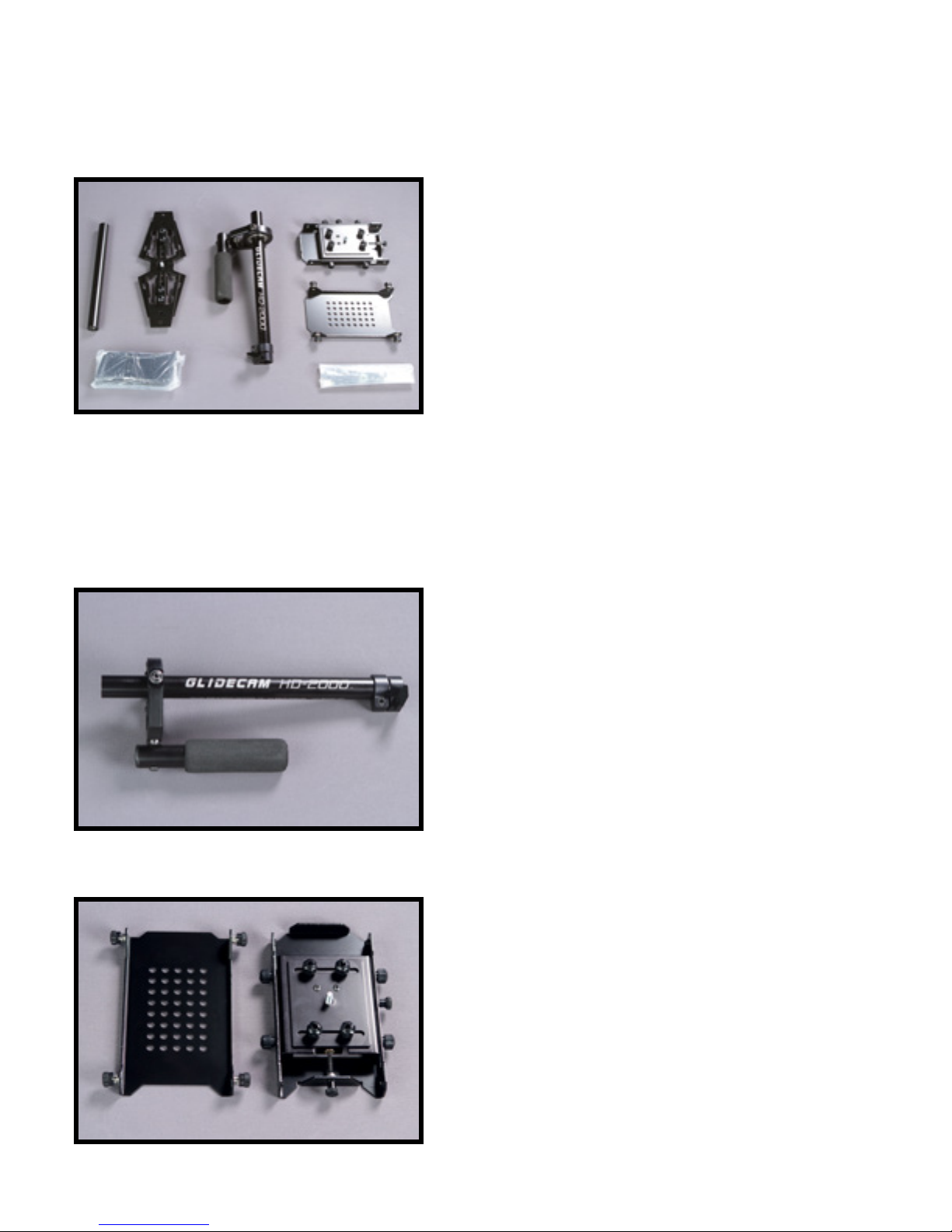
Each HD-Series Stabilizer’s offset, foam cushioned, handle grip is attached to a
free oating, three axis gimbal. This allows your hands to move up and down and
side-to-side, thereby isolating your hand’s unwanted motions from the camera. This
up and down movement alleviates the bouncing, pogo-type action often associated
with our competitor’s system. This is because their handle is not designed to have
the benecial ability to move up and down. This design feature, coupled with the over
all higher inertia of the HD-Series systems, produces a superior stabilization when
compared with our competition.
The unique and proprietary precision, three-axis gimbal incorporates several
adjustable axis convergence control. This allows all three axes to intersect for proper
operational alignment.
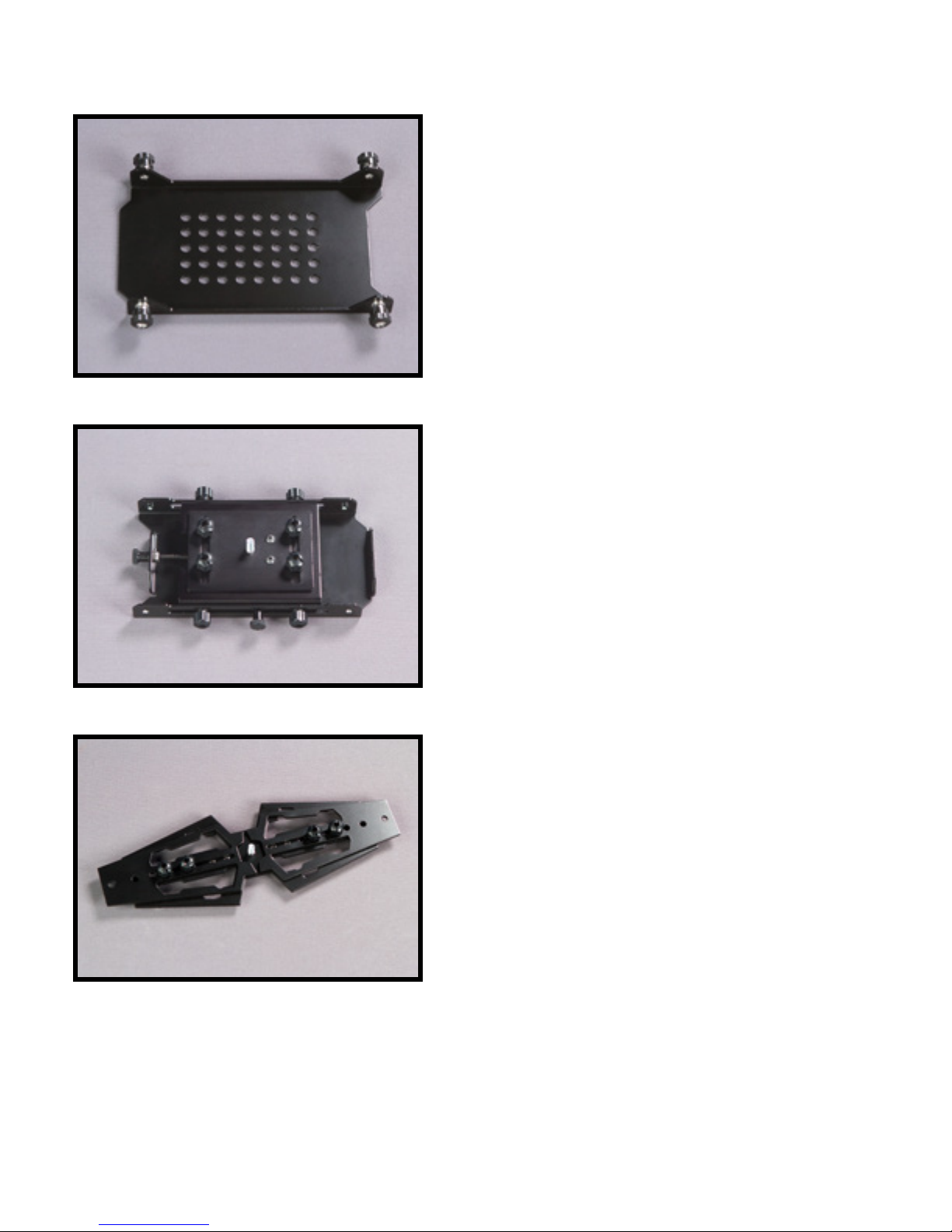
A camera-mounting platform with a quick-release, no-tools drop on camera plate
allows you to quickly attach or remove your camera. Ergonomic control knobs
allow quick, precise adjustments of the top stage’s back and forth and side-to-side
movement. These controls allow you to adjust the camera’s horizontal balance.
By varying the amount of counter weight on the base platform, or by changing the
length of the notool telescoping Central Post, you adjust the camera’s vertical balance.
When balanced properly the camera oats and you are ready to move into action.
#1 INTRODUCTION

5
The Glidecam HD-Series Stabilizers offer unparalleled controllability and ease of
use with their unique rigid, yet dynamically adjustable, control and weight distribution
surfaces. Setting up, controlling and adjusting the system’s balance is now quick and
precise.
A unique and proprietary dynamic base platform can expand or contract. This allows
you to easily adjust the system’s dynamic balance or to increase the system rotational
pan inertia.
Shot after shot and move after move, the Glidecam HD-Series Stabilizers deliver
beautifully smooth and professional results. With the Glidecam HD-Series you no
longer need a tripod or a dolly. All you need is your creativity, imagination, and
innovation.
Glidecam Industries is now becoming the choice of a generation. Glidecam makes
your decisions concerning stability and movement easy and simple. Simply rely
as so many have and still do, on using a Glidecam Camera Stabilizer. Glidecam
Industries, Inc., bringing two decades of Camera Stabilization with a wide range
of camera stabilizers, each optimized for various camera weights and shooting
conditions.
The Glidecam HD-Series requires practice and understanding to achieve professional
looking results. We highly recommend that the user read this manual thoroughly
before setting up and operating the HD-1000,HD-2000, or the HD-4000. Doing so
will save you time, and will minimize the risk of damage to your camcorder or the
Glidecam HD-1000, HD-2000, or HD-4000. It is important to perform and follow
the Set-up and Operation’s procedures in the proper sequence, so as to avoid both
frustration and possible accident.
If you have any needs for technical assistance, you can call our Technical Support
Line at 1-781-585-7900, Monday through Friday between the hours of 9:00am and
5:00pm Eastern Time.
We’re sure that once you have you Glidecam HD-1000, HD-2000, or HD-4000 up
and running, you will nd years of enjoyment with it.

6
#2 GLIDECAM HD-2000 PARTS AND
COMPONENTS
Figure 1
When you unpack your Glidecam HD-2000 you will
see that some Assembly is required. The contents of
the Glidecam HD-2000 box includes the following:
(See Figure 1)
MANUAL
CENTER POST
QUICK RELEASE PLATE
CAMERA MOUNTING PLATFORM
EXPANDABLE BASE PLATFORM
TELESCOPING POST
HARDWARE BAG
COUNTER WEIGHTS
TOOLS NEEDED:You will need a Standard and
Phillips Head Screwdrivers. (not included)
Figure 2
This is the Glidecam HD-2000 CENTRAL POST
with attached Gimbal assembly.
(See Figure 2)
***NOTE: The HD-1000 and the HD-4000 have
slightly different sizes.
WARNING: Do not adjust or tighten the factory
settings on the Gimbal, Handle, and Yoke. These
parts should remain loose and move freely, for
proper operation.
Figure 3
These are the pieces that makeup the HEAD
ASSEMBLY of the Glidecam HD-2000
1) QUICK RELEASE PLATE
2) CAMERA-MOUNTING PLATFORM
(See Figure 3)
***NOTE: The TELESCOPING POST
comes inserted into the CENTRAL
POST when shipped.

7
Figure 4
This is the QUICK RELEASE PLATE for the
Glidecam HD-2000 that you will attach to your
camera.
(See Figure 4)
(See SECTION 4 Attaching your Camera on PAGE
18 for Camera and QUICK RELEASE PLATE
Mounting)
***NOTE: The QUICK RELEASE PLATES for the
HD-1000 and the HD-4000 are different
Figure 5
This is the CAMERA-MOUNTING PLATFORM with
front-to-back and side-to-side movement
adjustment knobs.
Figure 6
This is the EXPANDABLE BASE PLATFORM.
(See Figure 6)
***NOTE: The HD-1000 and HD-4000 have slightly
different sizes.

8
Figure 7
This is the TELESCOPING POST.
(See Figure 7)
***NOTE: The HD-1000 and HD-4000 have slightly
different sizes.
Figure 8
Shown in bag are the COUNTER WEIGHT
PLATES to be attached to the EXPANDABLE
BASE PLATFORM.
(See Figure 8)
***NOTE: The HD-1000 has 8 weight plates and
HD-2000 and HD-4000 have 12 weight plates.
Figure 9
Shown in the bag is the HARDWARE set for the
Glidecam HD-2000.
(See Figure 9)
***NOTE: The HD-1000 and the HD-4000 have
slightly different HARDWARE.

9
Camera Mounting Screws
Black Bolts for Counter Plates
1/4” Washers Rubber Washers Black umb Nuts Counter Weight Plates

10
Figure 11
First place the EXPANDABLE BASE PLATFORM
rmly on a leveled surface.
(See Figure 11)
#3 ASSEMBLING YOUR GLIDECAM
HD-2000
Figure 12
Next nd the TELESCOPING POST and locate
the THREADED INSERT which can be found in the
bottom of the TELESCOPING POST.
(See Figure 12)

11
Figure 13
Connect the TELESCOPING POST to the
EXPANDABLE BASE PLATFORM by tightly
screwing the TELESCOPING POST rmly on to
the EXPANDABLE BASE PLATFORM.
(See Figure 13)
NOTE: Over tightening may cause damage to
both the THREAD INSERT located in side the
TELESCOPING POST and the EXPANDABLE
BASE PLATFORM.
Figure 14
At this point the rst step of your Glidecam
HD-2000 assembly should be complete with the
TELESCOPING POST securely fastened to the
EXPANDABLE BASE PLATFORM.
(See Figure 14)

12
Figure 15
Now nd the four BLACK BOLTS and gently slip
the RUBBER WASHERS on to the bolts.
(See Figure 15)
NOTE: Repeat this step for all four BLACK BOLTS.
Figure 16
Now insert all four of the BLACK BOLTS with
RUBBER WASHERS into the four slots located on
either end of the EXPANDABLE BASE PLATFORM.
(See Figure 16)
Figure 17
At this point the second step of your Glidecam
HD-2000 assembly should be complete, with all four
BLACK BOLT and RUBBER WASHER
combination protruding threw the EXPANDABLE
BASE PLATFORM.
(See Figure 17)

13
Figure 18
Next, take the COUNTER WEIGHT PLATES and
slide them down on to the BLACK BOLTS until they
are resting on EXPANDABLE BASE PLATFORM.
(See Figure 18)
NOTE: The holes in the weights match the
placement of the bolts.
Figure 19
Secure the COUNTER WEIGHT PLATES by using
the BLACK THUMB NUTS to prevent weight
movement.
(See Figure 19)
Figure 20
Now, both COUNTER WEIGHT PLATE stacks
should now be secured to the EXPANDABLE BASE
PLATFORM with the BLACK THUMB NUTS.
(See Figure 20)
NOTE: Expanding the EXPANDABLE BASE
PLATFORM length and moving the COUNTER
WEIGHT PLATES apart will create a pan inertia
and this will slow down the rotation of the sled
and reduce the side-to-side movement while
moving.

14
Figure 21
Now, insert the TELESCOPING POST with the
EXPANDABLE BASE PLATFORM up in to the
CENTRAL POST.
(See Figure 21)
Figure 22
The TELESCOPING CLAMP ADJUSTMENT
KNOB should be aligned with the center of the
EXPANDABLE BASE PLATFORM. To align
the TELESCOPING CLAMP ADJUSTMENT
KNOB simply rotate the entire CENTRAL
POST into the correct position, and tighten the
ADJUSTMENT KNOB. Also leave about one
inch of the TELESCOPING POST showing
below the TELESCOPING CLAMP. Having the
TELESCOPING CLAMP ADJUSTMENT KNOB
aligned correctly, although not technically needed
to make your Glidecam HD-2000 function correctly,
does make it easier to reach the knob later when
you use it.
(See Figure 22)
Figure 23
Securely tighten the ADJUSTMENT KNOB on the
TELESCOPING CLAMP by rotating the knob
clockwise.
(See Figure 23)
NOTE: The ADJUSTMENT KNOB should only
be tightened by hand.
WARNING: Do not over tighten the
ADJUSTMENT KNOB as it could cause thread
stripping.

15
Figure 24
At this point your Glidecam HD-2000 should have
the CENTRAL POST and TELESCOPING
POST aligned correctly on the EXPANDABLE
BASE PLATFORM assembly.
(See Figure 24)
NOTE: The amount of COUNTER WEIGHTS will
vary depending on your Camera weight. Don’t
worry about this to much, for later you will set
the number of COUNTER WEIGHTS to the correct
amount required for you specic Camera.
Figure 25
Next, locate the THREADED INSERT which
can be found in the top of the CENTRAL POST.
(See Figure 25)

16
Figure 26
Rotate and screw the CAMERA MOUNTING
PLATFORM into the THREADED INSERT in the top
of the CENTRAL POST.
(See Figure 26)
Figure 27
There are two ways to create this correct alignment.
The rst and easiest is to loosen the ADJUSTMENT
KNOB on the TELESCOPING CLAMP and rotate
the parts until correctly aligned. Then simply retighten
the ADJUSTMENT KNOB.
(See Figure 27)
NOTE: Remember to leave at least one inch of
the TELESCOPING POST showing below the
TELESCOPING CLAMP.

17
Figure 28
The second method to correctly align the parts is to use an Allen Wrench or Screwdriver
to loosen the “Screw” on the top part (See Figure 27) of the TELESCOPING CLAMP until
you can rotate the parts so they are correctly aligned. Then simply retighten the screw.
(See Figure 28)
NOTE: the second method of alignment is better because it keeps the TELESCOPING
CLAMP ADJUSTMENT KNOB aligned correctly (See Figure 22). Having the
TELESCOPING CLAMP ADJUSTMENT KNOB aligned correctly, although not
technically needed to make your Glidecam HD-2000 function correctly does make it
easier to reach the TELESCOPING CLAMP ADJUSTMENT KNOB later when in use.

18
#4 ATTACH YOUR CAMERA TO THE
GLIDECAM HD-2000
Figure 29
Now it is time to attach your Camera to the Glidecam
HD-2000’s QUICK RELEASE PLATE.
(See Figure 29)
Figure 30
First nd the THREADED INSERT on the bottom of
your camera.
(See Figure 30)
THREADED INSERT
Figure 31
Now preferably sit down in a chair and place your
Camera (base side up) in your lap. Then place and
center the QUICK RELEASE PLATE on the back
side of your Camera.
(See Figure 31)

19
Figure 32
Make sure the QUICK RELEASE PLATE is in
alignment square with the bottom of your Camera and
make sure the THREADED INSERT on the base of
your Camera is aligned with one of the MOUNTING
HOLES in the QUICK RELEASE PLATES.
(See Figure 32)
NOTE: You have a Video Camcorder or Film
Camera that is larger than the one used in this
Manual, then you might wish to rst nd the true
front to back center of gravity of your Camera by
rolling the base of your Camera on a pen until it
is balanced upon the pen, and mark this point
on your Camera’s side with a small piece of tape
or a grease pencil, and then use this marking to
center the QUICK RELEASE PLATE over your
Camera’s center of gravity.
Figure 33
Now use a CAMERA MOUNTING SCREW and a
1/4” WASHER attach the QUICK RELEASE PLATE
to your Camera.
(See Figure 33)
***NOTE: If the shorter CAMERA MOUNTING
SCREW does not work then try the slightly larger
CAMERAMOUNTING SCREW.Also try using more
than one 1/4” WASHER or no 1/4 WASHERS at all
if you have trouble with the mounting procedure.
You can also use the same MOUNTING SCREWS
and WASHERS for the HD-1000 and the HD-4000.
Figure 34
With your Camera base side up in your lap and with
the QUICK RELEASE PLATE in place, use a at head
screwdriver to secure the QUICK RELEASE PLATE
to your Camera using the CAMERA MOUNTING
SCREW and 1/4” WASHER combo you have just
selected.
(See Figure 34)
WARNING: Do not over tighten this screw. Over
tightening could break the THREADED INSERT
on your Camera.

20
Figure 35
If all is correct, the QUICK RELEASE PLATE should
now be securely fastened to your Camera.
(See Figure 35)
NOTE: If you can easily rotate the QUICK
RELEASE PLATE on the base of your Camera,
even though you have adequately tightened the
CAMERA MOUNTING SCREW, and you do not feel
comfortable tightening the CAMERA MOUNTING
SCREW any more, then you should think about
using some sort of a exible GASKET between
your Camera base and QUICK RELEASE PLATE.
You could use rubber tape, or a square at piece
of rubber (for example, creating one by cutting
up an old rubber dish washing glove)
Figure 36
Now securely place and center your Camera and
the attached QUICK RELEASE PLATE on top of the
CAMERA MOUNTING PLATFORM.
(See Figure 36)
NOTE: Make sure the four knobs are pulled all
the way out before installing. Once the plate
is installed push the four knobs in and rotate
clockwise to securely tighten.
Other manuals for Glidecam HD-1000
1
This manual suits for next models
2
Table of contents
Other Glidecam Industries Camcorder manuals