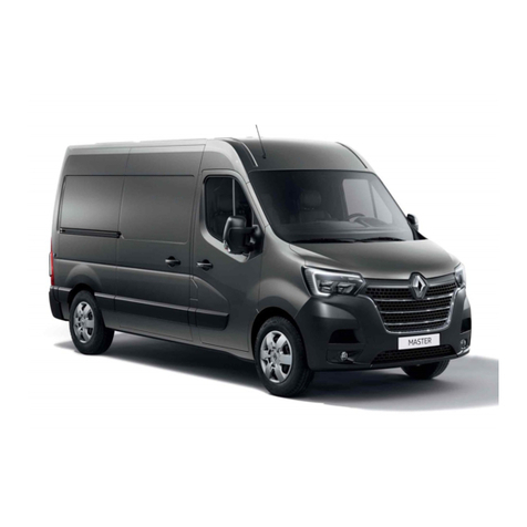
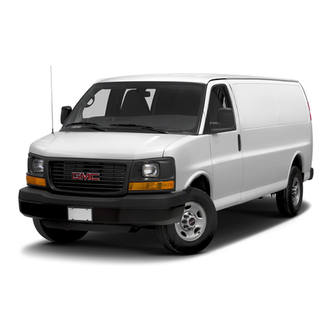
GMC CHEVROLET CITY EXPRESS CARGO VAN 2015 User manual

Page | 1
GENERAL MOTORS UPFITTER INTEGRATION
2015-18 CHEVROLET CITY EXPRESS CARGO VAN
BODY BUILDER MANUAL

2015-18 CHEVROLET CITY EXPRESS CARGO VAN BODY BUILDER MANUAL Page | 2
Revision 1.0 Release date October 2, 2017

2015-18 CHEVROLET CITY EXPRESS CARGO VAN BODY BUILDER MANUAL Page | 3
Contents
GENERAL INFORMATION............................................................................................................................................................. 9
FOREWORD ............................................................................................................................................................................. 9
IMPORTANT SAFETY NOTICE ................................................................................................................................................... 9
DISCLAIMER ............................................................................................................................................................................. 9
IMPORTANT REGULATORY INFORMATION ............................................................................................................................. 9
SAFETY INFORMATION .............................................................................................................................................................. 12
SUPPLEMENTAL RESTRAINT SYSTEM (SRS) PRECAUTIONS ................................................................................................... 12
Precaution for Supplemental Restraint System (SRS) “Airbag” and “Belt Pre-Tensioner”................................................ 12
SUPPLEMENTAL RESTRAINT SYSTEM (SRS) COMPONENT LOCATIONS........................................................................................ 13
OCCUPANT CLASSIFICATION SYSTEM........................................................................................................................................ 15
FRONT AIR BAG DEPLOYMENT ZONES ...................................................................................................................................... 16
FRONT AIR BAG MODULE LOCATIONS .................................................................................................................................. 16
Front Air Bag Modules —Overhead View............................................................................................................................. 17
Front Air Bag Modules —Driver Side.................................................................................................................................... 18
Front Air Bag Modules —Passenger Side ............................................................................................................................. 19
Driver Air Bag Deployment Width ......................................................................................................................................... 20
Front Passenger Air Bag Deployment Width ......................................................................................................................... 21
Headlining Cut —Front Side Curtain Air Bags Clearance for Bulkhead Installation.............................................................. 22
AIR BAG DEPLOYMENT KEEP-OUT ZONES ............................................................................................................................. 23
Front Air Bag Keep-Out Zones —Overhead View ............................................................................................................. 23
Front Air Bag Keep-Out Zone —Driver Side View............................................................................................................. 24
Front Air Bag Keep-Out Zone —Passenger Side View ...................................................................................................... 25
INFLATED AIR BAG ZONE DIMENSIONS ................................................................................................................................. 26
Driver and Passenger Air Bag Inflation Zones —Forward View........................................................................................ 26
Front Air Bag Inflation Zones —Overhead View............................................................................................................... 27
Front Air Bag Inflation Zones —Driver Side View ............................................................................................................. 28
Front Air Bag Inflation Zones —Passenger Side View....................................................................................................... 29
Side Curtain Air Bag Inflation Zones —Overhead View .................................................................................................... 30
Side Air Bag Inflation Zones —Overhead View................................................................................................................. 31
FRONT AIR BAG DEPLOYMENT ZONES (2017 MODEL YEAR)..................................................................................................... 32
FRONT AIR BAG MODULE LOCATIONS .................................................................................................................................. 32
Front Air Bag Modules —Overhead View (2017) ............................................................................................................. 32
Front Air Bag Modules —Driver Side (2017) .................................................................................................................... 33
Front Air Bag Modules —Passenger Side (2017) .............................................................................................................. 34

2015-18 CHEVROLET CITY EXPRESS CARGO VAN BODY BUILDER MANUAL Page | 4
Driver Air Bag Deployment Width (2017).......................................................................................................................... 35
Front Passenger Air Bag Deployment Width (2017).......................................................................................................... 36
HEADLINING CUT —FRONT SIDE CURTAIN AIR BAGS CLEARANCE FOR BULKHEAD INSTALLATION ................................ 37
AIR BAG DEPLOYMENT KEEP-OUT ZONES (2017).................................................................................................................. 38
Front Air Bag Keep-Out Zones —Overhead View ............................................................................................................. 38
Front Air Bag Keep-Out Zone —Driver Side View............................................................................................................. 39
Front Air Bag Keep-Out Zone —Passenger Side View ...................................................................................................... 40
INFLATED AIR BAG ZONE DIMENSIONS (2017)...................................................................................................................... 41
Driver and Passenger Air Bag Inflation Zones —Forward View........................................................................................ 41
Front Air Bag Inflation Zones —Overhead View............................................................................................................... 42
Front Air Bag Inflation Zones —Driver Side View ............................................................................................................. 43
Front Air Bag Inflation Zones —Passenger Side View....................................................................................................... 44
Side Curtain Air Bag Inflation Zones —Overhead View .................................................................................................... 45
Side Air Bag Inflation Zones —Overhead View................................................................................................................. 46
ALTERED VEHICLES .................................................................................................................................................................... 47
SAFETY INFORMATION .......................................................................................................................................................... 47
Safety / Emissions - Certification Labels for Altered Vehicles ........................................................................................... 47
BRAKE COMPLIANCE GUIDELINES ............................................................................................................................................. 49
Brake Compliance Guidelines (FMVSS and CMVSS 135) ....................................................................................................... 49
CENTER OF GRAVITY (CG).......................................................................................................................................................... 50
Vehicle Center of Gravity Measurement Process.................................................................................................................. 50
Introduction....................................................................................................................................................................... 50
Vehicle Center of Gravity Measurement Process.................................................................................................................. 51
List of Terms ...................................................................................................................................................................... 51
Recommended P ................................................................................................................................................................... 52
Measurement Methods.................................................................................................................................................... 52
Analysis Method .................................................................................................................................................................... 53
Results ............................................................................................................................................................................... 53
Vehicle Center of Gravity Envelope —Unloaded Vehicle Weight (UVW)......................................................................... 53
Maximum Unloaded Vehicle Weight (UVW) Resource Chart —2015 .............................................................................. 54
Maximum Unloaded Vehicle Weight (UVW) Resource Chart —2016 .............................................................................. 54
Maximum Unloaded Vehicle Weight (UVW) Resource Chart —2017 .............................................................................. 54
F/CMVSS 126 Electronic Stability Control Systems and F/CMVSS 135 Light Vehicle Brake Systems .................................... 55
FMVSS AND CMVSS REGULATION LIST...................................................................................................................................... 56
Standards............................................................................................................................................................................... 56
PRECAUTIONS............................................................................................................................................................................ 57
Precautions for Electrical CAN (Controller Area Network) System ....................................................................................... 57

2015-18 CHEVROLET CITY EXPRESS CARGO VAN BODY BUILDER MANUAL Page | 5
MODEL INFORMATION.............................................................................................................................................................. 58
LABEL INFORMATION ............................................................................................................................................................ 58
BODY DIMENSIONS ................................................................................................................................................................... 59
PASSENGER COMPARTMENT ................................................................................................................................................ 59
Seat Mounting Holes ......................................................................................................................................................... 59
RH Front Seat Front Mounting Hole Location ........................................................................................................................... 61
LH Front Seat Front Mounting Hole Location............................................................................................................................ 62
Seat Position Diagrams.............................................................................................................................................................. 63
SgRP Front Seat Dimension ............................................................................................................................................... 63
Body Dimensions ....................................................................................................................................................................... 64
CARGO AREA ......................................................................................................................................................................... 64
Interior Dimensions ............................................................................................................................................................... 64
Overall ............................................................................................................................................................................... 64
Wheel Well Clearance ........................................................................................................................................................... 65
Cut-away side view - RH .................................................................................................................................................... 65
Wheel Well Clearance ........................................................................................................................................................... 66
Cut-away side view - LH..................................................................................................................................................... 66
Cutaway Wheel Well and Rear Views ................................................................................................................................... 67
Cutaway Overhead View ....................................................................................................................................................... 68
D-Ring Tie-Downs (If Equipped) ............................................................................................................................................ 69
SIGN AREA ................................................................................................................................................................................. 70
RH Exterior Dimensions......................................................................................................................................................... 70
LH Exterior Dimensions.......................................................................................................................................................... 71
RH Front Door Exterior Dimensions....................................................................................................................................... 72
LH Front Door Exterior Dimensions ....................................................................................................................................... 73
RH Slide Door Exterior Dimensions ....................................................................................................................................... 74
LH Slide Door Exterior Dimensions........................................................................................................................................ 75
Hood Surface Exterior Dimensions........................................................................................................................................ 76
Hood Surface Exterior Dimensions (continued) .................................................................................................................... 77
Back Door Sign Area .............................................................................................................................................................. 78
Back Door Window Opening Sign Area ................................................................................................................................. 79
EXTERIOR................................................................................................................................................................................... 80
Front Door Opening Measurements ..................................................................................................................................... 80
RH Slide Door Opening Measurements —Without Slide Door Installed............................................................................. 81
LH Slide Door Opening Measurements —Without Slide Door Installed .............................................................................. 82
RH Slide Door Opening Measurements —With Slide Door Installed ................................................................................... 83
LH Slide Door Opening Measurements —With Slide Door Installed ....................................................................................... 84

2015-18 CHEVROLET CITY EXPRESS CARGO VAN BODY BUILDER MANUAL Page | 6
Back Door Opening Measurements .......................................................................................................................................... 85
Doors and Mirrors Dimensions.............................................................................................................................................. 86
Overhead View.................................................................................................................................................................. 86
Exterior Overall Dimensions .................................................................................................................................................. 87
UNIBODY AND FRAME........................................................................................................................................................... 88
Cross-member and Body Mount Dimensions ................................................................................................................... 88
Cross-member and Body Mount Dimensions (continued) ................................................................................................ 89
ELECTRICAL................................................................................................................................................................................ 90
FUEL
SYSTEMS
........................................................................................................................................................................... 91
FUEL SYSTEM PRECAUTIONS .................................................................................................................................................. 91
Fuel Pressure Release Procedure .......................................................................................................................................... 92
FILLER NECK AREAS ................................................................................................................................................................... 93
Chassis ................................................................................................................................................................................... 93
Fuel Filler Pipe and EVAP Canister Location .......................................................................................................................... 94
TANK LOCATION ........................................................................................................................................................................ 95
Tank Mounting ...................................................................................................................................................................... 95
Drilling Precaution Area ........................................................................................................................................................ 96
Fuel Tank —Floor Area ..................................................................................................................................................... 96
Drilling Precaution Area (continued)..................................................................................................................................... 97
Drilling Precaution Area Filler Neck....................................................................................................................................... 98
B-Pillar Area....................................................................................................................................................................... 98
TRAILER TOW............................................................................................................................................................................. 99
COOLING.................................................................................................................................................................................. 100
Engine Cooling System ........................................................................................................................................................ 100
HVAC........................................................................................................................................................................................ 101
Changes to the HVAC System .............................................................................................................................................. 101
HVAC System Component Locations................................................................................................................................... 101
Manual Air Conditioning System ..................................................................................................................................... 101
EXHAUST.................................................................................................................................................................................. 102
Exhaust System.................................................................................................................................................................... 102
Exhaust Measurements....................................................................................................................................................... 103
Exhaust System - Precautions.............................................................................................................................................. 104
WHEEL AND TIRE ..................................................................................................................................................................... 105
General ................................................................................................................................................................................ 105
STEERING AND SUSPENSION ................................................................................................................................................... 106
Vehicle Handling Information.............................................................................................................................................. 106
DRIVELINE................................................................................................................................................................................ 107


2015-18 CHEVROLET CITY EXPRESS CARGO VAN BODY BUILDER MANUAL Page | 7
TRANSMISSION........................................................................................................................................................................ 107
UNIBODY AND FRAME............................................................................................................................................................. 107
Jacking and Lifting Points ........................................................................................................................................................ 107
HIGH STRENGTH STEEL LOCATIONS ........................................................................................................................................ 108
Precaution in Repairing High Strength Steel (HSS).............................................................................................................. 108
High Strength Steel Locations ................................................................................................................................................. 109
WELDING ................................................................................................................................................................................. 112
VEHICLE INTERIOR ................................................................................................................................................................... 115
Modifications in the Vehicle Interior................................................................................................................................... 115
General ............................................................................................................................................................................ 115
Modifications in the Roof of the Cabin........................................................................................................................... 115
PAINT GENERAL INFORMATION .............................................................................................................................................. 115
ADHESIVE INFORMATION........................................................................................................................................................ 116
MSDS Information ........................................................................................................................................................... 116
REPLACING BOLTS ................................................................................................................................................................... 117

Tightening Torque Table...................................................................................................................................................... 117
ADD ON EQUIPMENT .............................................................................................................................................................. 118
ANTI-CORROSION PROTECTION........................................................................................................................................... 118
SHELVINGANDBULKHEADINSTALLATION ............................................................................................................................ 118
Bulkhead.......................................................................................................................................................................... 118
H Body Side and D-pillar Inner ........................................................................................................................................ 119
RH Body Side and D-pillar Inner .......................................................................................................................................... 120
LH Body Side and D-pillar Inner....................................................................................................................................... 121
Floor ................................................................................................................................................................................ 122
Interior Roof Bow Mounting Points ................................................................................................................................ 123
ROOF RACKS ............................................................................................................................................................................ 124
RECOMMENDED FLUIDS AND LUBRICANTS ............................................................................................................................ 126
SPECIFICATIONS:.................................................................................................................................................................. 126
Precaution for Fuel (Unleaded Regular Gasoline Recommended)...................................................................................... 127
Engine Coolant Recommendation....................................................................................................................................... 127
SUSPENSION ............................................................................................................................................................................ 128
General Specification (Front) .............................................................................................................................................. 128
Front Wheel Alignment (Unladen*1) .................................................................................................................................. 128
Wheel Turning Angle ........................................................................................................................................................... 129
General Specification (Rear)................................................................................................................................................ 130
Rear Wheel Alignment (Unladen*)...................................................................................................................................... 130
Wheels and Tires ..................................................................................................................................................................... 131

2015-18 CHEVROLET CITY EXPRESS CARGO VAN BODY BUILDER MANUAL Page | 8
Bulbs........................................................................................................................................................................................ 131
Exterior Bulbs ...................................................................................................................................................................... 131
Interior lamp/Illumination................................................................................................................................................... 131
Battery................................................................................................................................................................................. 131
Acronyms................................................................................................................................................................................. 132

2015-18 CHEVROLET CITY EXPRESS CARGO VAN BODY BUILDER MANUAL Page | 9
GENERAL INFORMATION
FOREWORD
This manual contains body builder’s information for the 2015 through 2017 Chevrolet City Express
Cargo Vehicle. In order to assure your safety and the efficient functioning of the vehicle, this guide
should be read thoroughly. All information in this guide is based on the latest product information at
the time of publication. The right is reserved to make changes in specifications and methods at any
time without notice.
IMPORTANT SAFETY NOTICE
The proper performance of procedures is essential for both the safety of the technician and the
efficient functioning of the vehicle. The methods in this Body Builder’s Guide are described in such a
manner that they may be performed safely and accurately. Methods vary with the procedures used,
the skills of the technician and the tools and parts available. Accordingly, anyone using procedures,
tools or parts which are not specifically recommended by General Motors and/or the OEM must first
be completely satisfied that neither personal safety nor the vehicle’s safety will be jeopardized by the
method selected.
DISCLAIMER
All information, specifications and illustrations in this manual are those in effect at the time of printing.
General Motors and/or the OEM reserves the right to change specifications or design without notice
and without obligation. The body builder, conversion company, aftermarket equipment manufacturer,
second stage manufacturer, upfitter, dealer and the vehicle purchaser are responsible to abide by the
regulations issued by the National Highway Traffic Safety Administration (NHTSA), the Occupational
Safety and Health Act (OSHA), state, local, or provincial government laws. These regulations and laws
may require the installation of additional equipment for the intended vehicle uses.
IMPORTANT REGULATORY INFORMATION
Emission standards and motor vehicle safety standards for new vehicles and equipment have been
established by the United States and Canadian Governments under the provisions of the Clean Air Act,
the Noise Control Act, and the National Traffic and Motor Vehicle Safety Act in the U.S., and the
Canadian Motor Vehicle Safety Act in Canada.
These Acts govern General Motors and the Original Equipment Manufacturer of the Chevrolet City
Express Cargo vehicles. They also govern dealers, body builders, and all others who manufacture and
market new motor vehicles and equipment. Part 568 of the Title 49 Code of Federal Regulations (CFR)
describes requirements for intermediate manufacturers, final-stage manufacturers, and manufacturers
who assume legal responsibility for a vehicle. This Body Builder’s Guide (Guide) partially fulfills both
General Motors and the OEM’s obligations as the original equipment manufacturer. Additionally, this
guide identifies regulatory requirements to assist intermediate and final stage manufacturers to
determine their obligations to conform to these standards. Compliance labels affixed to Chevrolet City
Express Cargo vehicles provide the status of initial compliance at the date of manufacture by the
Original Equipment Manufacturer (OEM). Subsequent modifications made to this vehicle may affect
the final certification of the engine, vehicle or equipment. Any and all body builders, conversion
companies, or dealers have the responsibility to certify the altered vehicle and equipment complies or
continues to comply with all

2015-18 CHEVROLET CITY EXPRESS CARGO VAN BODY BUILDER MANUAL Page | 10

2015-18 CHEVROLET CITY EXPRESS CARGO VAN BODY BUILDER MANUAL Page | 11
IMPORTANT REGULATORY INFORMATION (continued)
applicable motor vehicle safety standards and emissions regulations. The vehicle modifier is
responsible for making sure the modifications or installed equipment does not affect the safety of the
vehicle, which may result in a collision, serious personal injury or death. General Motors and/or the
OEM does not assume the responsibility as the final stage manufacturer for modified or altered
vehicles. General Motors and/or the OEM is not responsible for the final certification, product liability
claims, or warranty claims, resulting from any component, assembly, or system being altered by the
body builder, Conversion Company, dealer or vehicle purchaser. General Motors and/or the OEM is not
responsible for modifications which cause the vehicle to become noncompliant with any of the motor
vehicle safety standards, emissions regulations, or modifications that cause the vehicle to be or
become defective or unsafe.

2015-18 CHEVROLET CITY EXPRESS CARGO VAN BODY BUILDER MANUAL Page | 12
SAFETY INFORMATION
SUPPLEMENTAL RESTRAINT SYSTEM (SRS) PRECAUTIONS
Precaution for Supplemental Restraint System (SRS) “Airbag” and “Belt Pre-Tensioner”
WARNING:
To avoid rendering the SRS inoperative, which could increase the risk of personal injury or death in the
event of a collision which would result in air bag inflation, all maintenance must be performed by an
authorized General Motors dealer.
Improper maintenance, including incorrect removal and installation of the SRS, can lead to personal
injury caused by unintentional activation of the system.
• Do not use electrical test equipment on any circuit related to the SRS.
SRS wiring harnesses can be identified by yellow and/or orange harnesses or harness connectors.
Precautions When Using power tools (air or electric) and hammers.
WARNING:
When working near the Air bag Diagnosis Sensor Unit or other Air bag System sensors with the ignition
ON or engine running, DO NOT use air or electric power tools or strike near the sensor(s) with a
hammer. Heavy vibration could activate the sensor(s) and deploy the air bag(s), possibly causing
serious injury. When using air or electric power tools or hammers, always switch the ignition OFF,
disconnect the battery, and wait at least 3 minutes before performing any service.

2015-18 CHEVROLET CITY EXPRESS CARGO VAN BODY BUILDER MANUAL Page | 13
SUPPLEMENTAL RESTRAINT SYSTEM (SRS) COMPONENT LOCATIONS

2015-18 CHEVROLET CITY EXPRESS CARGO VAN BODY BUILDER MANUAL Page | 14
SUPPLEMENTAL RESTRAINT SYSTEM (SRS) COMPONENT LOCATIONS (continued)
1. Driver air bag module
2. Passenger air bag OFF indicator
3. Front passenger air bag module
4. Spiral cable
5. Air bag diagnosis sensor unit
(view with center console removed)
6. Instrument Cluster (SRS warning light)
7. Crash zone sensor
(view with front grille removed)
8. Front LH seat belt pre-tensioner (RH similar)
(view with lower center pillar cover removed)
9. Front side air bag satellite sensor LH (RH similar)
10. Front LH side air bag module (RH similar)
11. Front door satellite sensor LH (RH similar)
(view with front door finisher LH removed)
12. (A) Occupant classification control unit
(B) Occupant classification system sensor
13. LH side front curtain air bag module (RH similar)

2015-18 CHEVROLET CITY EXPRESS CARGO VAN BODY BUILDER MANUAL Page | 15
OCCUPANT CLASSIFICATION SYSTEM
WARNING:
After removal and installation of the front passenger seat, a zero point reset function must be
performed by a Chevrolet dealer using a special tool. If zero point reset is not performed, the
occupant classification system may not operate normally which may increase the risk of serious us
injury or death in a collision.
WARNING:
Do not disturb or modify the front passenger seat wiring. Failure to follow this instruction may cause
incorrect operation of the occupant classification system and front passenger air bag or system
failure and may increase the risk of serious injury or death in a collision.
The front passenger seat is equipped with seat weight sensors as part of the supplemental restraints
occupant classification system. The occupant classification sensors (weight sensors) are on the seat
cushion frame under the front passenger seat and are designed to detect an occupant and objects on
the seat. The front passenger air bag status lamp is illuminated when the system is disabled. For
occupant classification system and front passenger air bag operation, refer to the Owner’s Manual.
For repair of the front passenger seat, occupant classification system, air bags or if an air bag warning
lamp is illuminated, refer to a Chevrolet dealer. For seat mounting and fastener torque specifications,
refer to Seat Mounting Holes

2015-18 CHEVROLET CITY EXPRESS CARGO VAN BODY BUILDER MANUAL Page | 16
FRONT AIR BAG DEPLOYMENT ZONES
FRONT AIR BAG MODULE LOCATIONS
WARNING:
Modifications must not interfere with air bag modules or deployment zones. Damage to air bag
modules may cause serious personal injury or death. Objects placed within air bag deployment
zones may cause serious personal injury or death.
NOTE:
Do not add accessory items that, when installed, will interfere with the installed position of the air
bag or the zones of the deploying air bags.

2015-18 CHEVROLET CITY EXPRESS CARGO VAN BODY BUILDER MANUAL Page | 17
Front Air Bag Modules —Overhead View
= Air Bag Module Locations (No modifications in these areas.)
1. Driver air bag module
2. Side curtain air bag module, driver
3. Side air bag module, driver
4. Side air bag module, passenger
5. Side curtain air bag module, passenger
6. Front passenger air bag module
6
1
2
5
4
3
1
2
3
4
5
6

2015-18 CHEVROLET CITY EXPRESS CARGO VAN BODY BUILDER MANUAL Page | 18
Front Air Bag Modules —Driver Side
Front of vehicle
1. Side curtain air bag module
(located behind LH side of
headlining and across windshield
header)
2. Side air bag module (located
at outboard side of driver
seatback)
3. Driver air bag module (located
in steering wheel)
1
2
3
= Air Bag Module Locations (No modifications in these areas.)

2015-18 CHEVROLET CITY EXPRESS CARGO VAN BODY BUILDER MANUAL Page | 19
Revision: 1.0 11/12/2015
Front Air Bag Modules —Passenger Side
= Front of Vehicle
1.
Side curtain air bag module
(located behind RH side of
headlining and across windshield
header)
2. Front passenger air bag
module (located in RH side of
instrument panel)
3. Side air bag module (located at
outboard side of passenger
seatback)
1
3
2
= Air Bag Module Locations (No modifications in these areas.)

2015-18 CHEVROLET CITY EXPRESS CARGO VAN BODY BUILDER MANUAL Page | 20
Driver Air Bag Deployment Width
A. Center of the driver air bag module housing
B. 267.5 mm (10.53 in)
C. Maximum lateral projection of the deployed
driver air bag 535 mm (21.06 in)
D. 267.5 mm (10.53 in)
This manual suits for next models
3
Table of contents
Other GMC Automobile manuals

GMC
GMC Yukon Denali 2013 User manual

GMC
GMC 2001 Sonoma User manual

GMC
GMC 2013 Terrain User manual

GMC
GMC Sierra Denali 2017 User manual

GMC
GMC 1993 Safari User manual

GMC
GMC SIERRA 2002 User manual

GMC
GMC Hummer H2 2004 User manual

GMC
GMC 1998 Envoy User manual

GMC
GMC Yokon 2014 User manual

GMC
GMC 2010 Silverado Hybrid User manual

GMC
GMC 1995 Jimmy User manual

GMC
GMC 2005 Sierra Denali User manual

GMC
GMC Sierra 2500 HD 2024 User manual

GMC
GMC 2013 GMC Sierra User manual

GMC
GMC 1997 Sonoma User manual

GMC
GMC 2016 Yukon XL Denali User manual

GMC
GMC Express 2011 User manual

GMC
GMC Sierra Denali 1500 2023 User manual

GMC
GMC Terrain Denail User manual

GMC
GMC 2003 Savana User manual