GM
COACH
OPERATION
DOOB
CONTROLS
(Cont.)
Front entrance door can be manually closed from outside
after control lever
is
pulled from latched open position. From
outside, push door until closed and latched. Unlatch door from
outside by pulling on release button which extends through
body
at
front. After button
is
pulled, door can be pulled open
from outside (see illustration, page 9).
BMBBGBNCY DOOB
Emergency door is secured shut with lever type latch handle
(page 9) .
When
latch handle
is
lifted
or
not secure!y in place,
a switch acts to
light
tell-tale, "EMERG
DOOR,"
on
left
switch
panel in front
of
operator (page 4). An alarm buzzer also ·
sounds when latch is
not
secure.
On
standard coaches, engine
control switch must be placed in
"RUN"
position before tell-
tale and alarm buzzer are energized. Some coaches have a con-
stant circuit to emergency door.
IJlDIJ
WINDOWS
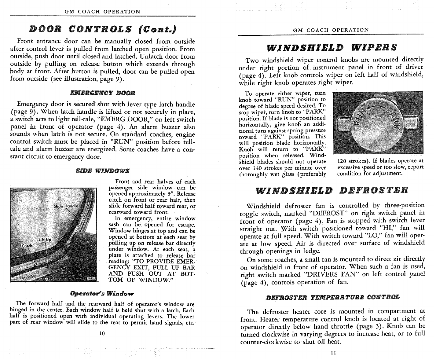
Front
and rear halves
of
each
passenger side window can be
opened approximately 8". Release
catch
on
front
or
rear half,
then
slide forward
half
toward
rear,
or
rearward toward front.
In
emergency, entire window
sash can be opened
for
escape.
Window
hinges
at
top
and
can be
opened
at
bottom at each seat by
pulling
up
on
release
bar
directly
under
window.
At
each seat, a
plate
is
attached
to
release
bar
reading:
"TO
PROVIDE
EMER-
GENCY
EXIT, PULL
UP
BAR
AND
PUSH
OUT
AT
BOT-
TOM
OF
WINDOW."
Operator's
Window
The
forward
half
and the rearward
half
of
operator's window are
hinged
in
the
center. Each window
half
is
held
shut
with
a latch. Each
half
is positioned open
with
individual operating levers.
The
lower
part
of
rear window will slide
to
the rear
to
permit
hand
signals, etc.
GM
COACH
OPERATION
WINDSBIBLD
WIPBBS
Two
windshield wiper control knobs are mounted directly
under
right
portion of instrument panel in front
of
driver
(page
4).
Left knob controls wiper on left half
of
windshield,
while right knob operates right wiper.
To
operate either
wip~r~
turn
knob toward
"RUN"
pos!Uon
to
degree
of
blade speed desired.
To
stop wiper,
turn
knob
to
"PARK"
position.
If
bla~e is
not
positione?
horizontally, give knob an addi-
tional
turn
against spring pressure
toward
"PARK"
position. This
will
position blade horizontally.
Knob will return to
"PARK"
position when released.
Wind-
shield blades should
not
operate
over 140 strokes
per
minute over
thoroughly wet glass (preferably
120 strokes). If blades operate
at
excessive speed
or
too slow,
report
condition for adjustment.
WINDSHIBLD
DBFBOSTBB
Windshield defroster fan
is
controlled
by
three-position
toggle switch, marked "DEFROST" on right switch panel in
front
of
operator (page 4). Fan
is
stopped with switch lev~r
straight out.
With
switch positioned toward
"HI,"
fan will
operate at full speed.
With
switch toward "LO," fan
':ill
Ofer-
ate at
low
speed. Air
is
directed over surface
of
wmdsh1eld
through openings in ledge.
On
some coaches, a small fan
is
mounted
to
direct air directly
on windshield in front
of
operator.
When
such a fan
is
used,
right switch marked "DRIVERS
FAN"
on left control panel
(page
4),
controls operation
of
fan.
DBFB.OSTBB
TBMPBBATUBB
CONTROL
The
defroster heater c0re is mounted in compartment at
front.
Heater
temperature control knob
is
located at right
of
operator directly below hand throttle (page 3). Knob can be
turned clockwise in varying degrees
to
increase heat, or to full
counter-clockwise
to
shut off heat.
11