321
45 6
Triangolo LED
4224
sorgenti luminose – lighting sources - source de lumière – Lichtquelle:
driver incorporato – built-in driver – driver int gr - eingebauter Treiber:
tonalità – tonality – tonalit – Farbton:
CRI:
aperture del fascio – beam angle - ouverture du faisceau – Lichtkegel:
6 led – W 39,5 tot
220-250V 50-60 Hz 350 mA
3500 K° standard
85
90° standard
IP 65 Classe II Conforme alle norme europee / Conformity with European standards EN 60 598-1
Conforme aux normes europ ennes / Laut europäischen Gesetze EN 60 598-1 Pagina / Page / Page / Seite 1/2
cod doc. 91365
cod. 089136500
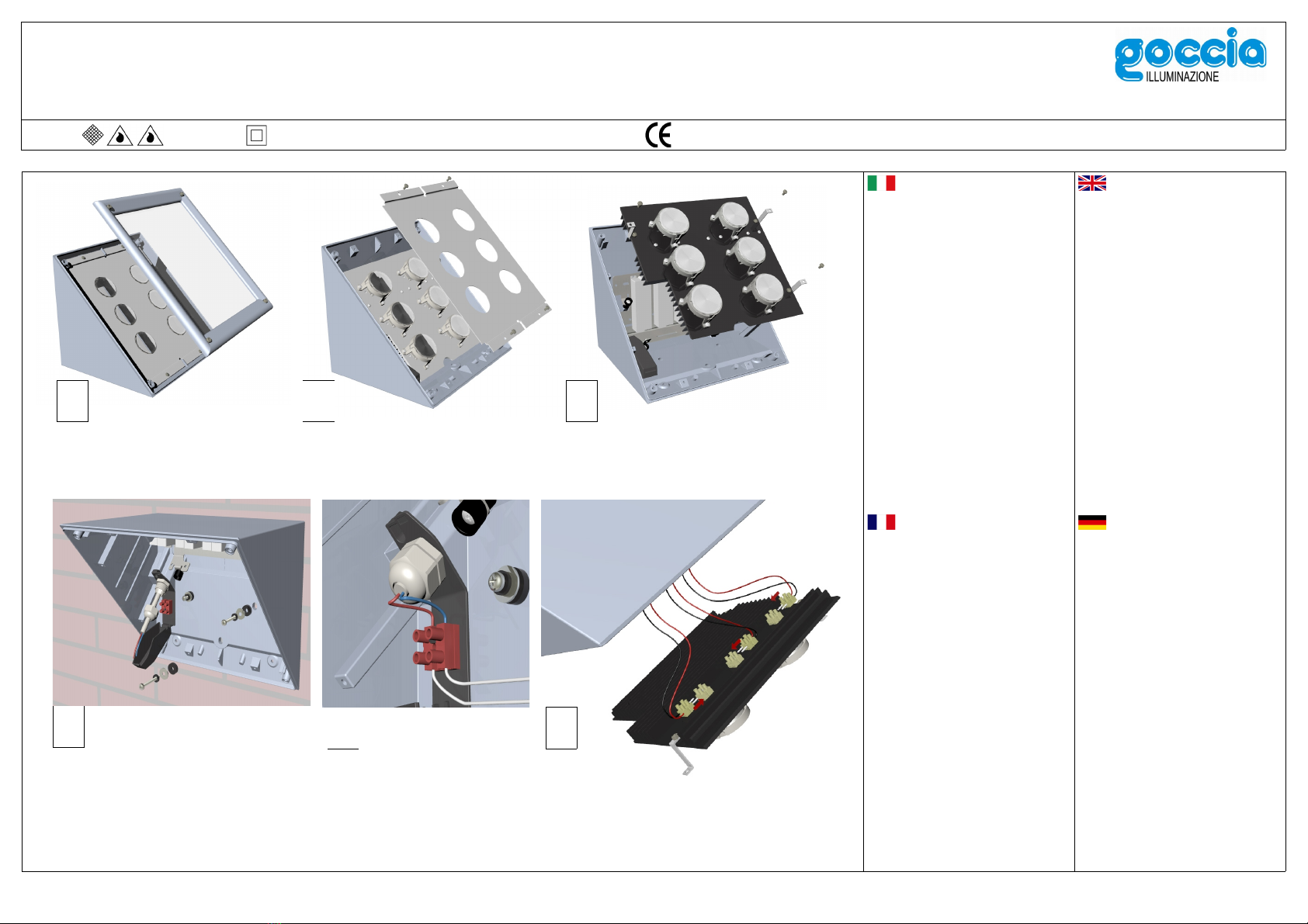
Prima di effettuare le operazioni di
installazione, assicurarsi che l'impianto
non sia in tensione.
Sez. minima fili unipolari 1,5 mm2 oppure
Cavo Ø 8 – 10 mm
Rimuovere cornice con vetro, piastra in
alluminio e gruppo led.
Aver cura di utilizzare viti di fissaggio a
muro e rondelle come da figura 4 per
mantenere una adeguata tenuta,
rispettando il grado di protezione IP.
Fissare l'apparecchio e cablare la
morsettiera.
Connettore le spine di alimentazione
bipolari alle spine fissate al gruppo led.
(figura 6)
Rimontare in sequenza il gruppo led,
piastra in alluminio e cornice con vetro.
Vedere a pag.2 le opzioni ottiche
Conservare le istruzioni.
Avant de commencer les op rations,
v rifiez que l'installation n'est pas sous
tension.
Utilisez fil de section 1,5 mm2, ou câble
de Ø 8 – 10 mm.
Retirez le cadre en verre, la plaque
d'aluminium et la plaque à LED.
Utilisez des vis et rondelles comme
d'après dessin 4, pour maintenir la
protection IP.
Fixer la lampe pour la fixation murale et
connectez le câble d'alimentation.
Brancher la fiches bipolaires de basse
tension à la plaque à LED. (dessin 6)
Remonter dans l'ordre la plaque à LED, la
plaque d'aluminium et le châssis avec le
verre.
Options optiques: pag. 2
Conserver les instructions.
Ensure the power is switched off before
starting operations.
Minimal wire section 1,5 mm2
or Ø 8 – 10 mm cable
Remove frame with glass, the aluminium
plate and the led plate.
Place screws, rubber and steel washers
as in drawing 4, to maintain the IP
protection grade.
Fix the fixture to the mounting wall and
connect the supply cable.
Connect the bipolar low voltage plugs to
the led plate. (drawing 6)
Reassemble in sequence the led plate,
the aluminium plate and the frame with
glass.
Optical options: page 2
Keep the instruction.
Bevor man an die Arbeit angeht, muß
man darauf achten, daß der Strom nicht
eingeschaltet ist.
Minimal Draht 1,5 mm2 oder
Ø 8 – 10 mm Kabel
Den Rahmen mit Glas, die
Aluminiumplatte und die LED-Platte
entfernen.
Die Befestigungsschrauben und die
Unterlegscheiben laut der Zeichnung 4
benutzen, um den IP Schutzgrad zu
behalten.
Die Leuchte an der Montagewand
Befestigen und das Netzkabel verkabeln
Die zweipolige Niederspannungs-
Steckern der LED-Platte verbinden.
(Zeichnung 6)
In der Reihenfolge, die LED-Platte, die
Aluminiumplatte und den Rahmen mit
Glas montieren.
Optische Optionen: Seite 2
Die Anleitungen bewahren.


 4.5/55 Operation manual")


