Goodmans GHC-58 User manual

Goodmans Product information Helpline:0870 873 0080
GHC-58

1. Safety Precautions
(Page 1)
IMPORTANTSAFEGUARDS
Foryour convenience a mains plughas been fitted to this appliance. For your safety
Please observe the following information.
1.Should the fuse in the plug fail removethe plug from the wall socket and replacethe
fusewitha 3AmpASTA approved to BS 1362 fuse.
2. Never use the plug without the fusecover fitted.Replacement fusecovers are
available fromyour dealer or most electrical retail outlets.
3. If the mains plug is cut off the cable, rewire the replacement plug in accordance with
instructiongiveinthismanual.
4.CAUTION: Under no circumstances should the discarded plug be inserted into the
mains socket. To prevent a shock hazard carefully dispose ofthe discardedplug.
Do not leave the pluglyingaround where childrenmight see it.
WARNING: To prevent fire or shock hazard do not expose this unit to rain or moisture.
PRE FITTED MAINS PLUGS
CAUTION: DANGEROUS VOLTAGES EXIST INSIDE THIS UNIT. DO NOT REMOVE
COVER (OR BACK).
NO USER SERVICEABLE PARTS INSIDE REFER SERVICING TO
QUALIFIED SERVICE PERSONNEL. DISCONNECT FROM MAINS
SUPPLY WHEN NOTIN USE.
This wires in this mains leadarecoloured
in accordance with the following wiring
codes:
Blue......................................Neutral
Brown........................................Live
Thiswiresinthismainsleadmustbe
connected tothe terminalsin theplug as
follows:
Blue Wire................................Nor Black
Brown Wire...............................Lor Red
Only a 3Amp fuse should be fitted in the
plug or a 3Amp fuse at the distribution
board.
WARNING: UNDER NO CIRCUMSTANCES MUSTTHE LIVE OR NEUTRAL
WIRES BE CONNECTED TO THE EARTHTERMINALINA3-PIN
MAINS PLUG. DISCONNECT FROM MAINS SUPPLY BEFORE
CLEANING.
L
N
BROWN
(LIVE)
L
BLUE
(NEUTRAL)
N
FUSE
CORD GRIP
This symbol means that this unit is double insulated.
An earth connection is not required.

2.SAFETYINSTRUCTIONS
22.DEC
Power source
This appliance should only be pluged into a 230VAC, 50Hz supply.
Safety considerations
Position the power supply lead and other leads so that they are not likely to be wallked
on or pinched by things placedon or against them.
Do not use the appliance in humid or damp conditions. Do not allowthe appliance to
get wet,ie. Dripping orsplashing,as this may be dangerous. Do not place water filled
objects, such as vases, on top of the appliance.
Make sure that no naked flame sources, such as candles, are placed on top of the
Appliance
.
Cleaning
Unplug the appliance beforecleaning it.
Do not use liquid or aerosol cleaners.
Clean the appliance witha soft, damp(not wet) cloth.
Ventilation
The slots and openings onthe appliance are forventilation. Do not cover or block
them as this could lead to overheating.
NEVER let children push anything intothe holes or slots on the case.
PACKING CONTENTS:
6 x speakers (frontx 2, rear x 2, centre x 1, sub-woofer(main unit) x 1)
1 x RemoteControl
2 x Batteries
3 x RCAto RCAcables
(Page 2)
Plastic bagscan be dangerous.To avoid danger of suffocation keep this bag away
frombabies and children.

V5.1/2.1CH
FL/FR
SL/SR
5.1CH
CEN
AUX
SUB SAT
TREBLE
TV
BASS
GHC58
POWER/
STANDBY
-
-
-
-
-
-
-
VOLUME
DVD-R
MUTE
3. LOCATION OF CONTROLS
123456
789
10
Front panel
Remote control
1
2
3
4
5
6
7
8
9
10
11
12
13
21
14
15
16
17
18
19
20
22
(Page 3)
DVD-R
1.Inputindicator for 5.1CH
2. Input for TV
3. Input for DVD-R
4. Input for SAT
5. Remote sensor
6. Input forAUX
7. Output mode for 5.1 channel
8. Output mode for V5.1CH
V5.1CH=VIRTUAL5.1CHANNEL
9. Output mode for 2.1 channel
10. Digital display forvolume, bass,treble adjustment
Possible settings as below:
Master volume: 0 -- 63
Bass: -8 - - 8
Treble: -8 -- 8
Subwoofervolume:0-- 15
Frontchannelvolume:0--15
Surroundchannel volume:0 -- 15
Center channel volume: 0 -- 15
indicator
indicator
indicator
indicator
indicator
indicator
indicator
When in standby this LED will be steady on.
When the audio output is muted this LED will flash.
1. Standby
2. Front speakers volume increase
3. Front speakers volume decrease
4. Surround speakers volume increase
5. Surround speakers volume decrease
6. Centre speaker volume
7. Centre speaker volume
8. Sub-woofer volume
9. Sub-woofer volume
10. Treble level
11. Treble level
12. Bass level
13. Bass level
14. Mute
15. 5.1 channel (input)
16. TV (input)
17. DVD-R (input)
18. SAT (input)
19.AUX(input)
20. 2.1/ virtual 5.1 channel mode switch
21. Master volume
22. Master volume
increase
decrease
increase
decrease
increase
decrease
increase
decrease
decrease
increase

1.TV
2.DVD-R
3.SAT
4.AUX
TV
DVD-R
SAT
AUX
4.SYSTEM CONNECTIONS(INPUT)
Whilst making and adjusting connectionsplease ensure that unit is disconnected fromthe mains
supply.
POWERCORD
AC 230V 50H z
SPEAKER
OUTPUT
SUB-WOOFERREAR PANEL
(Page 4)
DVD-R
Connect the following sockets to
the relevant output of the DVD
player.
Connect 2 channel audio components to the
"AUX L INPUT" and "AUX R INPUT" , "SAT L INPUT"
and "SAT R INPUT" , "DVD-R L INPUT" and "DVD-R
RINPUT", "TVLINPUT" and "TVRINPUT" SOCKETS.

5.SYSTEM CONNECTIONS(OUTPUT)
22.DEC
FL
FR
CEN
SL
SR
+
-
SPEAKER
OUTPUT
LR
AUX
SAT
DVD-R
TV
AUDIO
INPUT
SL SR
CEN SW
FL FR
5.1CH ON
OFF
FRONT LEFT FRONTRIGHT
CENTRE
REAR LEFT REAR RIGHT
SUB-WOOFER
REAR PANEL
Before connecting ensure that the main unit and all associated componentsare disconnected from the mains supply..
The connection cables are color coded White(+) and Grey (-), Ensure that these are connected to the respective
outputs on the rear of the main unit.
CONNECTINGYOUR LOUDSPEAKERS
BASE FIXING:
A. Put the wire through the hole at the base.
B. Use the screw to fixthe base to speaker box .
HOLE
SCREW
FL FR
CEN
SL SR
F3A/250V
POWERCORD
AC230 V 50Hz
SLOT
(Page 5)
The speakercable can be either bepassedthrough thehole
in the base or placed inthe sloton the underside ofthe speaker
before attaching the base.
1. Connect the centre speaker to the "CENTRESPEAKER OUT SOCKET" .
2. Connect the front left speaker tothe "FRONT LSPEAKER OUT SOCKET" .
3. Connect the front right speaker to the "FRONT R SPEAKER OUTSOCKET" .
4. Connect the surround(rear) left speaker to the " SURROUND LSPEAKER OUT SOCKET" .
5. Connect the surround(rear)right speaker to the "SURROUND R SPEAKER OUT SOCKET" .

TV
DVD-R
SAT
AUX
POWERCORD
AC 230V 50Hz
SPEAKER
OUTPUT
6. PREPARATION FORUSE
22.DEC
Replace the fuse located
on the back panel
"IMPORTANT: "
If the main unit fails to power up and no lights show on the
front panel. Check the following before returning the unit
for repair /replacement:
1. Make sure that the power switch on the back panel is
switched on.
2. Check /replace the 3Afuse inthe mains plug.
3. Check the 3 A fuse on back panel.
4. Fuse type(20mm F3A/250V)available from specialist
electrical shop.
"IMPORTANT: "
Remove the mains plug from the mains socket before
attempting to check /replace the fuse located on the
back panel.
Check /replace the 3A fuse located on the back panel of
the main unit. The fuse cover is removed by unscrewing
(anticlockwise)thecoverusingasmall flatbladed
screwdriver.
REAR PANEL
PLACEMENT OF SPEAKERS
REAR
CENTRE
FRONT
SUB-WOOFER
FRONT
REAR
(Page 6)

7. OPERATION
22.DEC
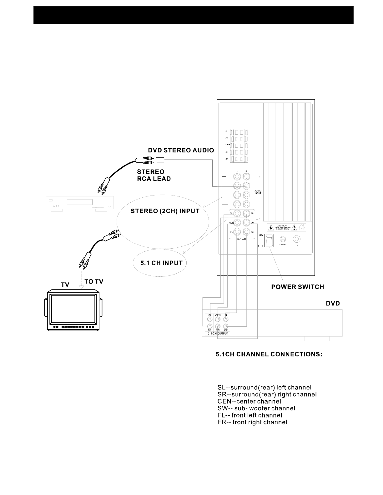
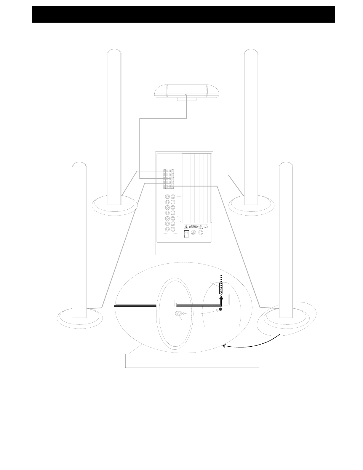
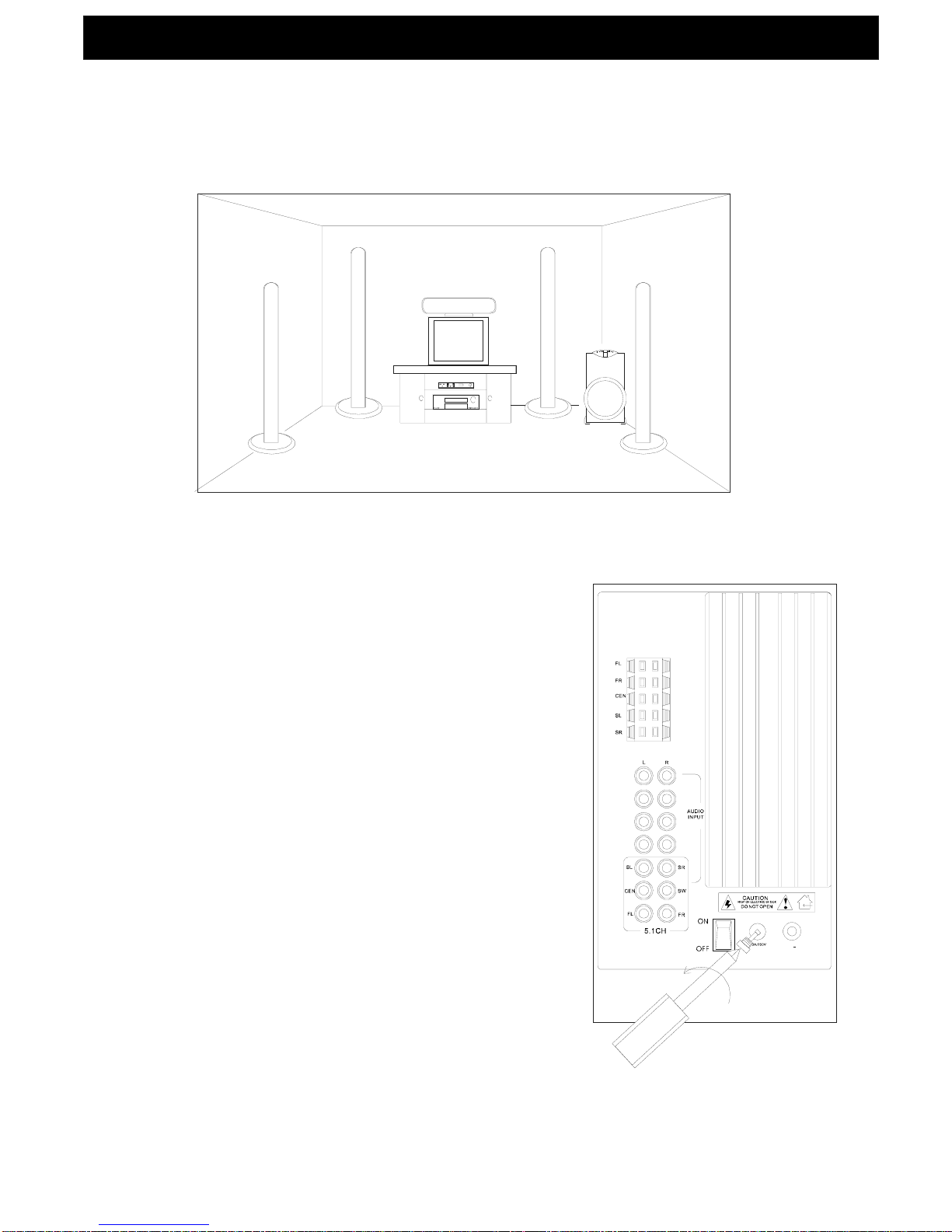
After connecting the speakers to the main unit(sub-woofer speaker), connect the mains plug into
the household mains outlet socket then switch the power on using the ON/OFF switch located on
the rear of sub-woofer.
Usewith 5.1 dolby surround source(DVD)
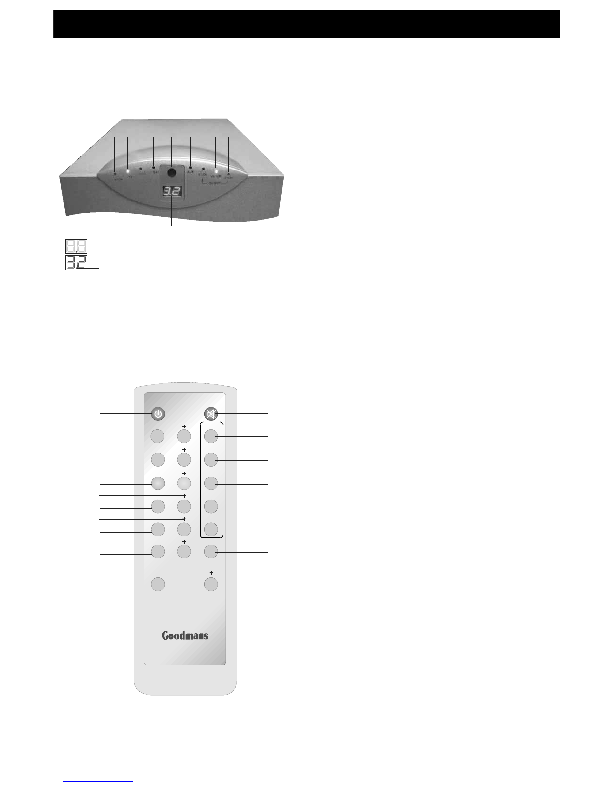
Centre speaker adjustment
Front speaker adjustment
Surround speaker adjustment
Bass adjustment / Treble adjustment
Sub-woofer speaker adjustment
Usewith stereo(L&R) source
Master volume adjustment
Standby mode
WARNING:
Press5.1CHbuttonon remotecontrolto select 5.1 channel input source for DVD.
NOTE: To listen to 5.1 dolby surroundsound, it is necessary to switch the DVD player (or other source) into 5.1 mode,
Pressthe CEN-, CEN+ button on theremotecontrol to adjust thevolume level ofcentre speaker.
PressFL/FR-, FL/FR+ button on the remotecontrol to adjust the volume levelof front speakers.
Press SL/SR-, SL/SR+ button on the remotecontrol to adjust the volume level of surround(rear) speakers.
Press BASS-, BASS+ button onthe remote control to adjust bass level.
PressTREBLE-,TREBLE+buttonontheremote controltoadjusttreble level.
PressSUB-,SUB+buttonon the remotecontroltoadjust volume levelof sub-woofer.
Pressthe AUX, SAT, DVD-R or TV buttonon the remote controlto selectone2CH input source.
TheAUX, SAT, DVD-R or TV LED light will illuminate on the front panel of sub-woofer.
PressV5.1/2.1CH buttonto enable theVIRTUAL 5.1 SURROUND SOUND.Otherwise
theCENTREand rear SURROUNDspeakers .
To increaseor decreasetheVolume level of all speakersat thesametime, presstheVOL-/VOL+ buttononthe
remote control.
PressPOWER/STANDBY button on the remote control toswitch off the system, (the Standby indicatorwill illuminate onthe
front panel of sub-woofer)
PLEASE NOTE THE SUB-WOOFER(MAIN UNIT), THEFRONTAND SURROUND SPEAKERS SUPPLIED WITHTHIS KITARE
NOT MAGNETICALLY SHIELDED AND MUST BEPOSITIONEDAWAY FROMA TV OR MONITOR SCREEN (EG.
SUB-WOOFER: AT LEAST 100CM, FRONTAND SURROUNDSPEAKERS: AT LEAST 60CM).FAILURE TO FOLLOW THIS
INSTRUCTION MAY RESULTIN LOCALISED DISCOLOURATION OFTHE SCREEN,WHICHMAYNOTBECORRECTABLE.
Mute
Pressthe MUTE button on the remote control to mute the audio. To cancel press MUTEagain.
(Forfurther informationplease consult the instructionmanual suppliedwith theDVD player.)
no sound willbeheard
from
8.SPECIFICATIONS
22.DEC
Power Supply:
Output Power
NOTE
AC 230V 50Hz
Sub-woofer : 50W
Front and Surround Speaker: 25W x 4
Centre Speaker : 25Wx 1
Power Consumption : 175W
Max Output Power(Audio) : 175W
: Specifications and design are subject to possible modifications without notice
∼
(Page 7)
Table of contents
Other Goodmans Home Cinema Speakers manuals