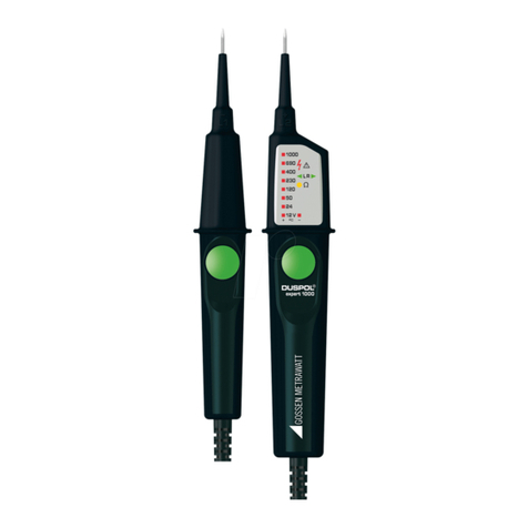
Gossen MetraWatt DUSPOL analog 1000 User manual

02/ 2019
DUSPOL
®
analog 1000
U202/ 2019
DUSPOL
®
analog 1000
U1
D D
analog
V
1
000
690
400
230
120
AC
DC
50
12
24
R
0
analog
V
1
000
690
400
230
120
AC
DC
50
12
24
R
0
V
1
000
690
400
230
120
AC
DC
50
12
24
R
0
DUSPOL
®
analog 1000
T.-Nr. 10079314.04 02/ 2019
1
2
3
4
5
6
7
8
9
J
DBedienungsanleitung
Operating manual
FMode d‘emploi
EManuel de instrucciones
ɂɧɫɬɪɭɤɰɢɹɡɚɟɤɫɩɥɨɚɬɚɰɢɹ
1iYRGNSRXåLWt]NRXãHþN\
Brugsanvisning
ȅįȘȖȓİȢȤȡȒıİȦȢ
H+DV]QiODWLXWDVtWiV
I,VWUX]LRQLSHUO¶XVR
Notkunarleiðbeiningar
NBruksanvisning
*HEUXLNVDDQZLM]LQJ
,QVWUXNFMDREVáXJL
InstrucĠLXQLGH8WLOL]DUH
ɂɧɫɬɪɭɤɰɢɹɩɨɷɤɫɩɥɭɚɬɚɰɢɢ
ɢɧɞɢɤɚɬɨɪɚɧɚɩɪɹɠɟɧɢɹ
SBruksanvisning
1
SRB
8SXWH]DUXNRYDQMH
Kullanma Talimati
www.GlobalTestSupply.com
Find Quality Products Online at: sales@GlobalTestSupply.com

02/ 2019
DUSPOL
®
analog 1000
U5 02/ 2019
DUSPOL
®
analog 1000
U602/ 2019
DUSPOL
®
analog 1000
U402/ 2019
DUSPOL
®
analog 1000
U3
D D DD
230 VAC
PE
NL
1000 VDC
230 VAC
PE
NL
PE
NL
230 VAC
A
C
B
D
E
F
www.GlobalTestSupply.com
Find Quality Products Online at: sales@GlobalTestSupply.com

02/ 2019
DUSPOL
®
analog 1000
5
nen die Funktion beeinträchtigen.
Achtung!
Eine Spannungsfreiheit kann nur durch eine zweipolige Prü-
fung festgestellt werden.
7. Drehfeldprüfung (Bild E/F)
- Umfassen Sie vollflächig beide Griffe L1 6und L2 7 um
eine kapazitive Kopplung gegen Erde zu gewährleisten.
- Legen Sie die Prüfspitzen L1/- 2und L2/+ 3an zwei
Außenleiter (Phasen) eines Drehstromnetzes (ohne Betä-
tigung der Drucktaster 5) und prüfen Sie ob die Außen-
leiterspannung von z.B. 400 V anliegt.
- Eine Rechtsdrehfolge (Phase L1 vor Phase L2) ist ge-
geben, wenn auf dem LC-Display 9ein „R“-Symbol
erscheint. Das LC-Display bleibt erloschen, wenn keine
Rechtsdrehfolge erkannt wurde.
- Die Drehfeldprüfung erfordert stets eine Gegenkontrolle!.
Zeigt das LC-Display die Rechtsdrehfolge über das „R“
Symbol an, muss bei der Gegenkontrolle mit vertauschten
Prüfspitzen L1/- 2und L2/+ 3das LC-Display erloschen
bleiben.
Zeigt das LC-Display in beiden Fällen ein „R“-Symbol an,
liegt eine zu schwache Erdung vor.
Hinweis:
Die Drehfeldprüfung ist ab 400 V - 900 V, 50/60 Hz (Phase
gegen Phase) im geerdeten Drehstromnetz möglich. Schutz-
kleidung und isolierende Standortgegebenheiten können die
Funktion beeinträchtigen
8. Technische Daten
- Vorschrift: DIN EN 61243-3: 2015, IEC 61243-3: 2014
- Nennspannungsbereich: 12 V bis AC/DC 1.000 V
- Nennfrequenzbereich f: 0 bis 60 Hz
- Max. Anzeigefehler: Un± 15 %, ELV Un+ 0 %, - 15 %
- Impedanz (Innenwiderstand) Messkreis/ Lastkreis:
NȍNȍ
- Stromaufnahme Messkreis: Is< 6,0 mA (1.000 V)
- Stromaufnahme Lastkreis: Is< 550 mA (1.000 V)
- Polaritätsanzeige: + 24 V LED, - 24 V LED, + 12 V LED,
- 12 V LED (bei Drucktasterbetätigung)
$XHQOHLWHUSUIXQJ3KDVHQDQ]HLJH8n230 V, 50 Hz/
60 Hz
'UHKIHOGSUIXQJ8n400 V, 50 Hz/ 60 Hz
9LEUDWLRQVPRWRU$QODXI8n200 V
- Überspannungskategorie: CAT IV 600 V,
CAT III 1000 V
- Schutzart: IP 65 (DIN VDE 0470-1 IEC/ EN 60529)
6 - erste Kennziffer: Schutz gegen Zugang zu gefährlichen
Teilen und Schutz gegen feste Fremdkörper, staubdicht
5 - zweite Kennziffer: Geschützt gegen Strahlwasser. Auch
bei Niederschlägen verwendbar.
-
max. zulässige Einschaltdauer:
ED = 30 s (max. 30 Sekunden), 600 s Pause
- Gewicht: ca. 250 g
- Verbindungsleitungslänge: ca. 1000 mm
- Betriebs- und Lagertemperaturbereich: - 20 °C bis + 45 °C
(Klimakategorie N)
- Relative Luftfeuchte: 20 % bis 96 % (Klimakategorie N)
- Rückregelzeiten (thermischer Schutz):
Spannung/Zeit: 230 V/30 s, 400 V/9 s, 690 V/5 s, 1000 V/2 s
9. Allgemeine Wartung
Reinigen Sie das Gehäuse äußerlich mit einem sauberen tro-
ckenen Tuch.
10. 8PZHOWVFKXW]
Bitte führen Sie das Gerät am Ende seiner Lebens-
dauer den zur Verfügung stehenden Rückgabe- und
Sammelsystemen zu.
Operating Manual
DUSPOL®analog 1000
Before using the DUSPOL®analog 1000 voltage tester, pro-
ceed as follows: Please read the operating manual and abso-
lutely observe the safety instructions!
Table of Contents
6DIHW\LQVWUXFWLRQV
2. Device description
3. Functional test before use to ensure the absence of
voltage of an installation
4. Checking the absence of voltage of an installation
5. Load connection with vibration motor
([WHUQDOFRQGXFWRUWHVWSKDVHLQGLFDWLRQ
7. Phase sequence test
8. Technical data
9. General maintenance
10. Environmental protection
6DIHW\LQVWUXFWLRQV
- During use, touch the tester at the insulated handles L1 6
and L2 7only and do not touch the probe tips L1/- 2and
L2/+ 3!
- Check the voltage tester for correct functioning immedi-
ately before and after using it in order to ensure the ab-
sence of voltage of an installation (see section 3)! Do not
use the voltage tester, if one or more indications are not
working or if it does not seem to be ready for operation!
Please repeat the test with another voltage tester after-
wards.
- The voltage tester must be used only within the stated
nominal voltage range and in electrical installations of up
to 1,000 V AC/DC!
- The voltage tester must be used only in electric circuits of
overvoltage category CAT III with max. 1,000 V or over-
www.GlobalTestSupply.com
Find Quality Products Online at: sales@GlobalTestSupply.com

02/ 2019
DUSPOL
®
analog 1000
6
voltage category CAT IV with max. 600 V for phase-to-
earth measurements.
- The voltage tester is designed for being used by qualified
electricians and under safe working conditions.
- The LED step indicator is intended for indicating the volt-
age range. It is not intended for measuring purposes.
- Creating a voltage tester for more than 30 seconds volt-
age (maximum duty cycle = 30 s)!
- Do not dismantle the voltage tester!
- The voltage tester must be protected against contamina-
tion and damaging of the housing surface.
- To protect them against damaging, provide the probe tips
with the enclosed probe tip protector 1after using the
voltage tester!
- Please observe that the impedance (internal resistance) of
the voltage tester influences the indication of interference
voltages (capacitively or inductively induced)!
Depending on the internal impedance of the voltage detector,
there will be a different capability of indicating the presence
or absence of operating voltage in case of the presence of
interference voltage.
Low-impedance voltage testerLPSHGDQFHNȍLQWHU-
ference voltage is suppressed or reduced:
Avoltage tester of relatively low internal impedance, compared
WRWKHUHIHUHQFHYDOXHRINȍZLOOQRWLQGLFDWHDOOLQWHUIHU-
ence voltages having an original voltage value above the ELV
level (50 V AC/ 120 V DC). When in contact with the parts
to be tested, the voltage tester may discharge temporarily the
interference voltage to a level below the ELV, but it will be back
to the original value when the voltage tester is removed.
When the indication “voltage present” does not appear, it is
highly recommended to install earthing equipment before start-
ing work.
High-impedance voltage testerLPSHGDQFH!Nȍ,QWHU-
ference voltage will not be suppressed or reduced:
A voltage tester of relatively high internal impedance, com-
SDUHG WR WKH UHIHUHQFH YDOXH RI Nȍ PD\ QRW SHUPLW WR
clearly indicate the absence of operating voltage in case of
presence of interference voltage. When the indication “voltage
present” appears on a part that is expected to be disconnected
IURPWKH LQVWDOODWLRQLW LVKLJKO\ UHFRPPHQGHGWR FRQ¿UPE\
another means (e.g. use of an adequate voltage tester capable
of distinguishing between operating voltages and interference
voltages, visual inspection of the disconnecting point of the
electric circuit, etc.) that there is no operating voltage on the
part to be tested and to conclude that the voltage indicated by
the voltage tester is an interference voltage.
9ROWDJH WHVWHUV FDSDEOH RI GLVWLQJXLVKLQJ EHWZHHQ RSHU-
DWLQJYROWDJH DQGLQWHUIHUHQFH YROWDJHE\PHDQVRIORDG
connection:
A voltage tester stating two values of internal impedance has
passed a performance test of managing interference voltages
and is (within technical limits) able to distinguish operating volt-
age from interference voltage and has a means to directly or
indirectly indicate which type of voltage is present.
Electrical symbols on the device:
Symbol Meaning
Important documentation!
The symbol indicates that the guide described
in the manual, to avoid any risks
Device or equipment for working under voltage
Push-button
Alternating voltage (AC)
Direct voltage (DC)
Direct and alternating voltage (DC/AC)
Earth (voltage to ground)
Push-button (manually actuated); indicates that
the respective indications are made only with
both push-buttons being actuated
Clockwise phase sequence; the phase se-
quence can be indicated only at 50 or 60 Hz
and in an earthed mains
Plunger coil level indicator
2. Device description
1Probe tip protector
2Probe tip L1/-
3Probe tip L2/+
4Plunger coil level indicator
5Push-button
6Handle L1
7Display handle L2
8LED step indicator
9LC display mit "R" symbol für external conductor test
(phase indication) and phase sequence indicator (clock-
wise)
J+/- LEDs of the polarity indication
3. Functional test before use to ensure the absence of
voltage of an installation
- Check the voltage tester for correct functioning
immediately before and after using it!
- Test the voltage tester with familiar voltage sources, e.g.
with a 230 V socket.
- Do not use the voltage tester, if the voltage indication, the
phase indication and the vibration motor are not working
properly!
www.GlobalTestSupply.com
Find Quality Products Online at: sales@GlobalTestSupply.com

02/ 2019
DUSPOL
®
analog 1000
7
4. Checking the absence of voltage of an installation
(figure A/B)
For checking the installation, please test the absence of volt-
age by checking the voltage indication, the phase indication
(the phase indication only works in an earthed AC voltage
mains) and the vibration motor (the vibration motor is activated
by actuating both push-buttons). The installation is only free
of voltage, if all three test circuits (voltage indication, phase
indication and vibration motor) are signaling the absence of
voltage.
- Apply the two probe tips L1/+ 2and L2/- 3to the system
parts to be tested.
- The level of voltage applied is indicated by means of the
LED step indicator 8.
- Actuate both push-buttons 5to connect the plunger coil
level indicator 4, the 12 V LED step (+/ -) and an internal
load in the voltage tester.
- Alternating voltages (AC) are indicated by the +24 V LED
and the -24 V LED lighting up simultaneously.
- Direct voltages (DC) are indicated by the +24 V LED or the
-24 V LED lighting up. The polarity indication Jshows the
SRODULW\ (+ or -) applied to the probe tip L2/+ 3.
- To differentiate between low-energy and high-energy volt-
ages (e.g. capacitively induced interference voltages), an
internal load in the voltage tester can be connected by ac-
tuating both push-buttons (see section 5).
5. Load connection with vibration motor ¿JXUH$%
Both handles L1 6and L2 7are equipped with push-buttons
5. Actuate both push-buttons to switch to a lower internal re-
sistance. Here, voltage is applied to a vibration motor (motor
with unbalanced mass). From approx. 200 V on, this motor is
set in rotary motion. With the voltage increasing, the motor's
speed and vibration increases as well. The duration of the test
with a lower internal resistance (load test) depends on the level
of voltage to be measured. In order to avoid an inadmissible
warming of the device, it is provided with a thermal protection
(controlled reduction). With this controlled reduction, the speed
of the vibration motor is reduced and the internal resistance
increases.
The load connection (with both push-buttons being actuated)
can be used ...
- to suppress reactive voltages (inductive and capacitive
voltages),
- to charge capacitors,
- to trip 10 mA/ 30 mA RCD safety switches. The tripping
of the RCD safety switch is done by testing the external
conductor (phase indication) to PE (earth). (figure D)
([WHUQDOFRQGXFWRUWHVWSKDVHLQGLFDWLRQ¿JXUH&
- Fully grasp the handles L1 6and L2 7, in order to en-
sure a capacitive coupling to earth.
- Apply the probe tip L2/+ 3to the system part to be tested.
During the single-pole external conductor test (phase in-
dication), make absolutely sure not to touch the probe tip
L1/- 2and that it remains contactless.
- If an "R" symbol is shown on the LC display 9, the exter-
nal conductor (phase) of an AC voltage is applied to this
system part.
Note:
The single-pole external conductor test (phase indication)
can be carried out in an earthed mains from 230 V, 50/60 Hz
(phase to earth) on. Protective clothing and insulating condi-
tions on site might impair the function.
Attention!
The absence of voltage can only be determined by means of
a two-pole test.
7. Phase sequence test¿JXUH()
- Fully grasp both handles L1 6and L2 7, in order to en-
sure a capacitive coupling to earth.
-
Apply the probe tips L1/-
2
and L2/+
3
to two external
conductors (phases) of a three-phase mains (without actua-
tion the push-buttons
5
) and check whether the external
conductor voltage of e.g. 400 V is applied
.
- A clockwise phase sequence (phase L1 before phase L2)
is given, if an "R" symbol is shown on the LC display 9.
Nothing is shown on the LC display, if no clockwise phase
sequence has been detected.
- The phase sequence test always requires a countercheck!
If the LC display shows the clockwise phase sequence by
means of the "R" symbol, the LC display must show noth-
ing during the countercheck with the probe tips L1/- 2
and L2/+ 3being inverted.
If the LC display shows the "R" symbol in both cases, the
earthing is too weak.
Note:
The phase sequence test can be carried out in an earthed
three-phase mains from 400 V - 900 V, 50 / 60 Hz (phase to
phase) on. Protective clothing and insulating conditions on site
might impair the function.
8. Technical data
- regulation: DIN EN 61243-3: 2015, IEC 61243-3: 2014
- nominal voltage range: 12 V to 1,000 V AC/DC
- nominal frequency range f: 0 to 60 Hz
- max. indication error: Un±15%, ELV Un+0% -15%
- Impedance (internal resistance) of measuring circuit/ load
FLUFXLWNȍNȍ
- current consumption of measuring circuit: Is< 6,0 mA
(1,000 V)
- current consumption of load circuit: Is< 550 mA (1,000 V)
- polarity indication: + 24 V LED, - 24 V LED, + 12 V LED,
- 12 V LED (with push-buttons being actuated)
H[WHUQDO FRQGXFWRU WHVW SKDVH LQGLFDWLRQ 8n230 V,
50 Hz/ 60 Hz
SKDVHVHTXHQFHWHVW8n400 V, 50 Hz/ 60 Hz
YLEUDWLRQPRWRUVWDUW8n200 V
www.GlobalTestSupply.com
Find Quality Products Online at: sales@GlobalTestSupply.com
02/ 2019
DUSPOL
®
analog 1000
8
F
- overvoltage category: CAT IV 600 V, CAT III 1,000 V
- protection category: IP 65 (DIN VDE 0470-1 IEC/ EN
60529)
6 - first index: protection against access to dangerous
parts and protection against solid impurities, dustproof
5 - second index: protected against water jets. The device
can also be used in the rain.
-
max. allowable Duty cycle: 30 s (max. 30 seconds), 600 s off
- weight: approx. 250g
- length of connecting cable: approx. 1,000 mm
- operating temperature and storage temperature range:
- 20 °C to + 45 °C (climatic category N)
- relative air humidity: 20 % to 96 % (climatic category N)
- times of controlled reduction (thermal protection):
voltage/time: 230 V/30 s, 400 V/9 s, 690 V/5 s, 1000 V/2 s
9. General maintenance
Clean the exterior of the device with a clean dry cloth.
10. Environmental protection
Please lead the device at the end of its useful life to
the available return and collection systems.
Mode d'emploi
DUSPOL®analog 1000
Avant d'utiliser le contrôleur de tension DUSPOL®analog 1000
: Lisez le mode d'emploi et tenez impérativement compte des
consignes de sécurité !
Table des matières
1. Consignes de sécurité
'HVFULSWLRQGHO¶DSSDUHLO
3. Contrôle de fonctionnement avant l'utilisation afin
d'assurer l'absence de tension d'une installation
9pULILFDWLRQGHODEVHQFHGHWHQVLRQGXQHLQVWDOODWLRQ
5. Connexion de charge avec moteur à vibration
6.
&RQWU{OHGXFRQGXFWHXUH[WpULHXULQGLFDWLRQGHSKDVH
7. Test d'ordre de phases
8. Caractéristiques techniques
9. Entretien général
3URWHFWLRQGHO¶HQYLURQQHPHQW
1. Consignes de sécurité :
- Lors de l’utilisation, ne touchez l’appareil qu’aux poignées
isolées L1 6et L2 7et ne touchez jamais les pointes
d'essai L1/- 2et L2/+ 3!
- Contrôlez toujours le bon fonctionnement du contrôleur
de tension immédiatement avant et après de l'utiliser afin
d’assurer l’absence de tension de l’installation (voir para-
graphe 3)! Le contrôleur de tension ne doit être utilisé dès
lors qu'une ou plusieurs affichages ne fonctionnent plus
ou dès lors l'appareil n'est plus opérationnel ! Ensuite,
répétez ce contrôle au moyen d’un autre contrôleur de
tension.
- Le contrôleur de tension ne doit être utilisé que dans la
plage de tension nominale spécifiée et dans les installa-
tions électriques jusqu'à 1.000 V AC / DC !
- Le contrôleur de tension ne doit être utilisé que dans les
circuits électriques de la catégorie de surtension CAT III
avec un maximum de 1.000 V ou de la catégorie de sur-
tension CAT IV avec des conducteurs de 600 V max. par
rapport à la terre.
- Le contrôleur de tension est conçu afin d'être utilisé par
des électrotechniciens en combinaison avec des procé-
dés de travail sûrs.
- L'affichage de niveau par LED sert à indiquer la plage de
tension et n'est donc pas prévu afin d'effectuer des me-
sures.
- Création d'un testeur de tension pour tension de plus de
30 secondes (cycle d'utilisation maximal)
- Le contrôleur de tension ne doit être pas démonté !
- Protégez le contrôleur de tension contre les impuretés ain-
si que contre l'endommagement de la surface du boîtier.
- Comme protection contre les blessures, les pointes d'es-
sais doivent être munies du protecteur de pointe d'essai
ci-inclus 1suite à l'utilisation du contrôleur de tension !
- Tenez compte du fait que l'impédance (résistance interne)
du contrôleur de tension influencera l'affichage de ten-
sions parasites (couplées de façon capacitive ou induc-
tive) !
Selon l’impédance interne du contrôleur de tension, il existe
une capacité différente à indiquer la présence ou l’absence de
tension de service en présence d’une tension parasite.
Contrôleur de tension à basse impédance (impédance
NȍODWHQVLRQSDUDVLWHVHUDVXSSULPpHRXUpGXLWH
Un contrôleur de tension présentant une impédance interne
relativement basse, comparée à la valeur de référence de
NȍQ¶LQGLTXHSDVWRXWHVOHVWHQVLRQVSDUDVLWHVGRQWODWHQ-
sion d’origine est supérieure au niveau de la TBT (tension très
basse, 50 V AC/ 120 V DC). Lorsque le contrôleur de tension
est en contact avec les pièces à contrôler, il peut évacuer tem-
porairement la tension parasite à un niveau inférieur à la TBT
(tension très basse), puis revenir à la valeur d’origine suite au
retrait du contrôleur de tension.
Si l'indication « présence de tension » n'apparaît pas, il est for-
tement recommandé de mettre le dispositif de mise à la terre
avant de commencer le travail.
Contrôleur à haute impédance LPSpGDQFH!Nȍ/D
tension parasite ne sera pas supprimée ou réduite :
Un contrôleur de tension présentant une impédance interne
relativement élevée, comparée à la valeur de référence de 100
NȍQHSHXWSDVFODLUHPHQWLQGLTXHUO¶DEVHQFHGHWHQVLRQGH
service en cas de présence d'une tension parasite. Si l’indica-
www.GlobalTestSupply.com
Find Quality Products Online at: sales@GlobalTestSupply.com
Other manuals for DUSPOL analog 1000
2
This manual suits for next models
1
Table of contents
Languages:
Other Gossen MetraWatt Circuit Tester manuals