Gotop GT-1110-MTR User manual

GT-1110-MTR
GPS Receiver Module
www.gotop-zzu.com
Page 1 of 33
Revision: V2.0.1-January 2015
General Description
The Gotop GT-1110-MTR is a complete
GPS engine module that features super sensitivity,
ultra low power and small form factor. The GPS
signal is applied to the antenna input of module,
and a complete serial data message with position,
velocity and time information is presented at the
serial interface with NMEA protocol or custom
protocol.
Its –165dBm tracking sensitivity extends
positioning coverage into place like urban
canyons and dense foliage environment where
the GPS was not possible before. The small form
factor and low power consumption make the
module easy to integrate into portable device like
PNDs, mobile phones, cameras and vehicle
navigation systems.
Applications
LBS (Location Based Service)
PND (Portable Navigation Device)
Vehicle navigation system
Mobile phone
Figure: GT-1110-MTR Top View
Features
Build on high performance, low-power
MediaTek MT3337 chip set
Ultra high Track sensitivity: -165dBm
Extremely fast TTFF at low signal level
Built in high gain LNA
Low power consumption: Max [email protected]
NMEA-0183 compliant protocol or custom
protocol
Operating voltage: 2.8V to 4.3V
Operating temperature range:-40to85℃
SMD type with stamp holes
Small form factor: 10.1x9.7x2.2mm
RoHS compliant (Lead-free)

GT-1110-MTR
GPS Receiver Module
www.gotop-zzu.com
Page 2of 33
Revision: V2.0.1-January 2015
1 Description...................................................................................................................................................................... 3
1.1 General Description...............................................................................................................................................3
1.2. Key Features.........................................................................................................................................................4
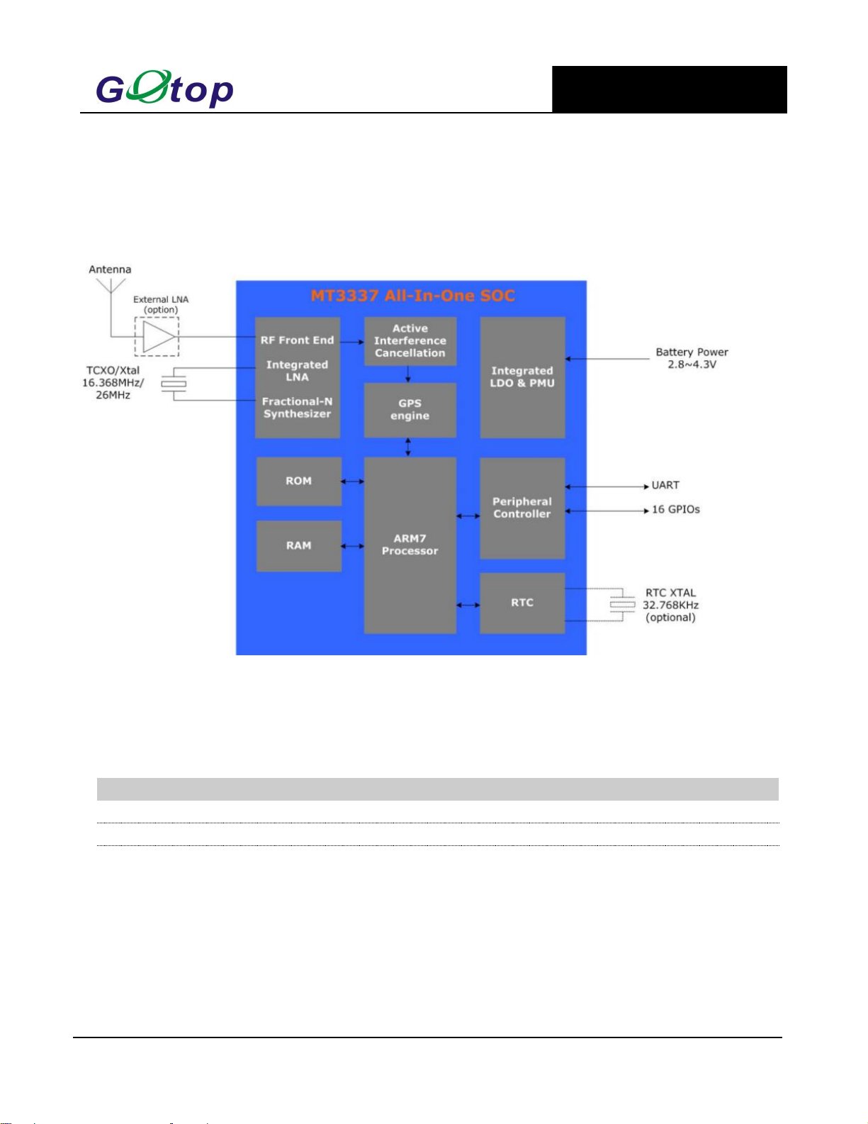
1.3. Block Diagram..................................................................................................................................................... 5
1.4. Protocols Supported by the Module.....................................................................................................................5
2 Application...................................................................................................................................................................... 6
2.1. Pin Assignment.....................................................................................................................................................6
2.2. Pin Definition....................................................................................................................................................... 6
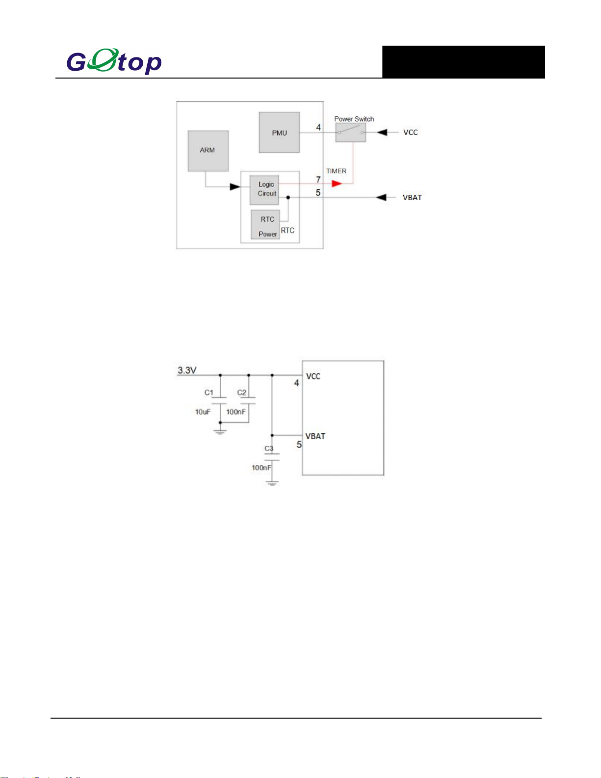
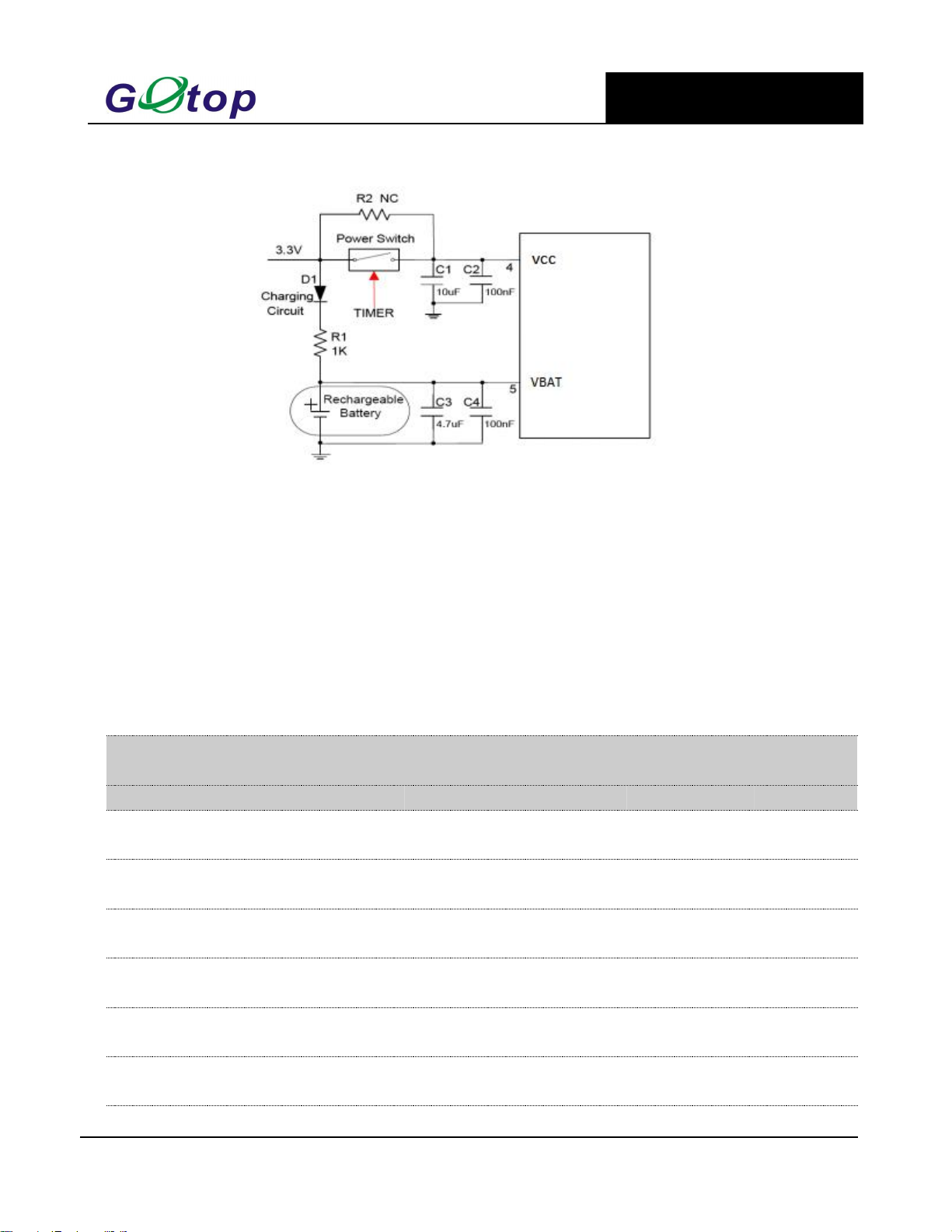
2.3. Power Supply....................................................................................................................................................... 8
2.4. Operating Modes................................................................................................................................................ 10
2.4.1. Full on Mode........................................................................................................................................... 11
2.4.2. Standby Mode..........................................................................................................................................11
2.4.3. Backup Mode.......................................................................................................................................... 11
2.4.4. Periodic Mode......................................................................................................................................... 13
2.4.5. AlwaysLocateTM Mode......................................................................................................................... 15
2.4.6. FLP Mode................................................................................................................................................16
2.5. UART Interface.................................................................................................................................................. 16
2.6. EASY Technology..............................................................................................................................................18
2.7. Multi-tone AIC................................................................................................................................................... 18
2.8. LOCUS...............................................................................................................................................................19
2.9. PPS VS. NMEA................................................................................................................................................. 19
3 Antenna Interfaces....................................................................................................................................................... 20
3.1. PCB Design Guide............................................................................................................................................. 20
3.2. External Active Antenna.................................................................................................................................... 20
4 Electrical, Reliability and Radio Characteristics......................................................................................................22
4.1. Absolute Maximum Ratings...............................................................................................................................22
4.2. Operating Conditions......................................................................................................................................... 22
4.3. Current Consumption......................................................................................................................................... 23
4.4. Electrostatic Discharge.......................................................................................................................................23
4.5. Reliability Test................................................................................................................................................... 24
5 Mechanical Dimensions............................................................................................................................................... 24
6 Manufacturing, Packaging and Ordering Information........................................................................................... 25
6.1. Assembly and Soldering.....................................................................................................................................25
6.2. Moisture Sensitivity........................................................................................................................................... 25
6.3. ESD Protection...................................................................................................................................................25
6.4. Tape and Reel Packaging................................................................................................................................... 26
7 Appendix References....................................................................................................................................................27
8 NMEA 0183 Protocol....................................................................................................................................................28

GT-1110-MTR
GPS Receiver Module
www.gotop-zzu.com
Page 3of 33
Revision: V2.0.1-January 2015
1 Description
1.1 General Description
GOTOP GT-1110-MTR GPS module embedded LNA brings high performance of MTK positioning engine to the
industrial applications. It is able to achieve the industry’s highest level of sensitivity, accuracy and TTFF with the
lowest power consumption in a small-footprint leadless package. With 66 search channels and 22 simultaneous
tracking channels, it acquires and tracks satellites in the shortest time even at indoor signal level.
GT-1110-MTR module combines many advanced features including EASY, AIC, LOCUS, AlwaysLocate ™, FLP.
These features are beneficial to accelerate TTFF,improve sensitivity,save consumption. The module supports various
positioning,navigation and industrial applications including autonomous GPS, SBAS (including WAAS,
EGNOS,MSAS, and GAGAN),QZSS, and AGPS.
EASY technology as the key feature of GT-1110-MTR is one kind of AGPS. Capable collecting and processing all
internal aiding information like GPS time,Ephemeris, Last Position,etc.,the GPS module delivers a very short TTFF
in either Hot or Warm start.
GT-1110-MTR module is a SMD type module with the compact 10.1mm×9.7mm×2.2mm form factor. It can be
through the 18-pin pads embedded in your applications. It provides necessary hardware interfaces for connection with
the main PCB.
Made of lead-free technology, conforms to the RoHS standard, Single patch, two times more rapid application of
SMT scheme.

GT-1110-MTR
GPS Receiver Module
www.gotop-zzu.com
Page 4of 33
Revision: V2.0.1-January 2015
1.2. Key Features
Table 1: Key Features
Parameter
Specification
Power Supply
•Supply voltage: 2.8V~4.3V Typical: 3.3V
Power Consumption
•Acquisition: 25mA @VCC=VBAT=3.3V
•Tracking: 20mA @VCC=VBAT=3.3V
•Standby: 1.0mA @VCC=VBAT=3.3V
•Backup: 7uA @VBAT=3.3V
Receiver Type
•Code 66 search channels, GPS&QZSS L1 1575.42MHz C/A
•22 simultan ous tracking channels
Sensitivity
•Tracking: -165dBm
•Re-acquisition: -156dBm
•Acquisition: -148dBm
TTFF (EASY enabled)
•Cold start: 15s typ @-130dBm
•Warm start: 5s typ @-130dBm
•Hot start : 1s typ @-130dBm
TTFF (EASY disabled)
•Cold start(Autonomous): 35s typ @-130dBm
•Warm start (Autonomous): 30s typ @-130dBm
•Hot start (Autonomous): 1s typ @-130dBm
Horizontal Position
Accuracy (Autonomous)
•<2.5m CEP @-130 dBm
Update Rate
•1Hz
Accuracy of 1PPS Signal
•Typical accuracy: ±10ns
•Time pulse width 100ms
Acceleration Accuracy
•Without aid: 0.1m/s²
Dynamic Performance
•Maximum altitude: 18,000m
•Maximum velocity: 515m/s
•Acceleration: 4G
UART Port
•UART Port: TXA and RXA
•Supports baud rate from 4800bps to 115200bps, 9600bps by
default
•UART port is used for NMEA output, MTK proprietary
commands input
Temperature Range
•Normal operation: -40°C ~ +85°C
•Storage temperature: -45°C ~ +125°C
Physical Characteristics
•Size: 10.1±0.15 ×9.7±0.15 ×2.2±0.1mm
•Weight: Approx.0.41g

GT-1110-MTR
GPS Receiver Module
www.gotop-zzu.com
Page 5of 33
Revision: V2.0.1-January 2015
1.3. Block Diagram
The following figure shows a block diagram of GT-1110-MTR module. It consists of a single chip GPS IC which
includes the RF part and Baseband part, a LNA, a SAW filter, a TCXO, a crystal oscillator.
Figure 1: Block Diagram
1.4. Protocols Supported by the Module
Table 2: Protocols Supported by the Module
Protocol
Type
NMEA
Output, ASCII, 0183, 3.01
PMTK
Input, MTK proprietary protocol

GT-1110-MTR
GPS Receiver Module
www.gotop-zzu.com
Page 6of 33
Revision: V2.0.1-January 2015
2 Application
The module is equipped with a 18-pin SMT pad that connects to your application platform. Sub-interfaces included
in the pad are described in details in the following chapters.
2.1. Pin Assignment
Figure 2: Pin Assignment
2.2. Pin Definition
Power Supply
Pin Name
Pin No.
I/O
Description
DC Characteristics
Comment
VCC
8
I
Main power supply
Vmax=4.3V
Vmin=2.8V
Vnom=3.3V
Supply current not less than
100mA.
VBAT
6
I
Backup power supply
Vmax=4.3V
Vmin=1.5V
Vnom=3.3V
Supply power for RTC
domain. The VBAT pin can
be directly supplied power by
battery or connect it to VCC.
GND
1.10.
12
G
Ground.
Assure a good GND connection
to all GND pins of the module,
preferably with a large ground
plane.
Reset
Pin Name
Pin No.
I/O
Description
DC Characteristics
Comment
RESET
9
I
System reset
VILmin=-0.3V
VILmax=0.8V
VIHmin=2.0V
VIHmax=3.6V
Low level active. If unused,
keep this pin open or connect
it to VCC.

GT-1110-MTR
GPS Receiver Module
www.gotop-zzu.com
Page 7of 33
Revision: V2.0.1-January 2015
UART Port
Pin Name
Pin No.
I/O
Description
DC Characteristics
Comment
RXA
3
I
Receive data
VILmin=-0.3V
VILmax=0.8V
VIHmin=2.0V
VIHmax=3.6V
TXA
2
O
Transmit data
VOLmin=-0.3V
VOLmax=0.4V
VOHmin=2.4V
VOHmax=3.1V
RXB
17
I
Receive data
VILmin=-0.3V
VILmax=0.8V
VIHmin=2.0V
VIHmax=3.6V
If not used, this pin is left
vacant.
TXB
16
O
Transmit data
VOLmin=-0.3V
VOLmax=0.4V
VOHmin=2.4V
VOHmax=3.1V
If not used, this pin is left
vacant.
RF Interface
Pin Name
Pin No.
I/O
Description
DC Characteristics
Comment
RF_IN
11
I
External active
antenna RF input
Characteristic impedance of
50Ω
VCC_RF
14
O
Active antenna
power output
Vnom=3.3V
Output Voltage RF section.
VCC_RF can be selected
according to the type of
antenna.
Other Interfaces
Pin Name
Pin No.
I/O
Description
DC Characteristics
Comment
PPS
3
O
One pulse
per second
VOLmin=-0.3V
VOLmax=0.4V
VOHmin=2.4V
VOHmax=3.1V
Synchronized at rising
edge, the pulse width
is100ms. If unused, keep
this pin open.
GPIO Interfaces
Pin Name
Pin No.
I/O
Description
DC Characteristics
Comment
GPIO0
5
I/O
Baud rate control
GPIO1
18
I/O
Baud rate control

GT-1110-MTR
GPS Receiver Module
www.gotop-zzu.com
Page 8of 33
Revision: V2.0.1-January 2015
Figure 3: GPIO1/GPIO2 control circuit
Table 3: Module baud rate control
2.3. Power Supply
VCC pin supplies power for BB, RF, I/O, LNA, short protection and antenna detection circuit. The load current of
VCC varies according to the VCC level, processor load, the number of tracked satellites and the rate of satellite
re-acquisition. Using external active antenna will consume additional 11mA from our module. So it is important to
supply sufficient current and make the power clean and stable. VCC supply ripple voltage should meet the
requirement: 54mV (RMS) max @f=0 …3MHz and 15mV (RMS) max@f >3MHz. You should choose the LDO
without built-in output high-speed discharge function to keep long output voltage drop-down period. The decouple
combination of 10uF and 100nF capacitor is recommended nearby VCC pin.
The VBAT pin supplies power for RTC domain. It should be valid when power on the module. The voltage of
RTC domain ranges from 1.5V to 4.3V. In order to achieve a better TTFF, RTC domain should be valid all the time. It
can supply power for SRAM memory in RTC domain which contains all the necessary GPS information for quick
start-up and a small amount of user configuration variables.
The module's internal power construction is shown as below.
VCC supplies power for PMU, and VBAT supplies power for RTC domain. TIMER signal highlighted in red in
the following figure belongs to RTC domain and can be used to control the power switch on/off.
GPIO1(R1)
GPIO2(R2)
Baud rate state
NC
NC
9600bps
0Ω
NC
4800bps
NC
0Ω
115200bps
0Ω
0Ω
38400bps

GT-1110-MTR
GPS Receiver Module
www.gotop-zzu.com
Page 9of 33
Revision: V2.0.1-January 2015
Figure 4: Internal Power Construction
Power supply solutions for GT-1110-MTR module are listed as the following.
The simplest power circuit for GT-1110-MTR module is 3.3V power source connected to VCC pin and VBAT pin
of the module directly. In this case, once you powered on the module, the full cold start will be implemented.
Figure 5: Reference Circuit for Power Supply
If your power supply circuit adopts the design mentioned above , GT-1110-MTR module does not support EASY
technology and backup mode as well as other modes related to it,e.g. AlwaysLocate™backup mode.
The other way is feeding VBAT through a backup battery directly. The module will enter into backup mode when
power source (3.3V) is cut off. Furthermore,it is necessary to add an external charging circuit.for rechargeable battery.
The detailed schematic (mount R2 with 0R to replace Power switch) is shown as there is no charge source when
power source (3.3V) is cut off. MS621FE FL11E from Seiko is recommended. The consumption of VBAT is as low as
7uA in backup mode.
The schematic with power supply circuit is shown as below. As power source (3.3V) is always valid and the
battery is charged continuously, the capacity of the battery can be small. The detailed schematic for power switch
circuit is shown in Figure 6.

GT-1110-MTR
GPS Receiver Module
www.gotop-zzu.com
Page 10 of 33
Revision: V2.0.1-January 2015
For more details about backup mode, periodic backup mode and AlwaysLocate™backup mode, please refer to the
related chapters.
Figure 6: Reference Charging Circuit for Chargeable Battery
VCC does not supply power for RTC domain in GT-1110-MTR module, so the VBAT pin must be powered
externally. Furthermore, it is strongly recommended to supply power to VBAT through a backup battery, which can
ensure GT-1110-MTR module supports EASY technology and improves TTFF after next restart. For details about
TTFF, please refer to chapter 1.2.
2.4. Operating Modes
The table below briefly illustrates the relationship among different operating modes of GT-1110-MTR module.
Table 4: Module States Switch
Current
Mode
Next Mode
Backup
Standby
Full on
Periodic
AlwaysLocate
FLP
Backup
N/A
N/A
Refer to
chapter 2.4.3
N/A
N/A
N/A
Standby
N/A
N/A
Send any data
via UART
N/A
N/A
N/A
Full on
Refer to
chapter 2.4.3
PMTK161
N/A
PMTK225
PMTK225
PMTK262
Periodic
N/A
N/A
Refer to
chapter 2.4.4
N/A
N/A
N/A
Always
Locate
N/A
N/A
Refer to
chapter 2.4.5
N/A
N/A
N/A
FLP
N/A
N/A
Refer to
chapter 2.4.6
N/A
N/A
N/A

GT-1110-MTR
GPS Receiver Module
www.gotop-zzu.com
Page 11 of 33
Revision: V2.0.1-January 2015
2.4.1. Full on Mode
Full on mode includes tracking mode and acquisition mode. Acquisition mode is defined as the module starts to
search satellites, determine visible satellites and coarse carrier frequency as well as code phase of satellite signals.
When the acquisition is completed, it switches to tracking mode automatically. Tracking mode is defined as the
module keeps tracking satellites and demodulates the navigation data from the specific satellites.
When the combination of VCC and VBAT is valid, the module will enter into full on mode automatically and
follow the default configurations as below. You can refer to chapter 2.3 about internal power construction to have a
good comprehension. You can also use PMTK commands to change the configurations to satisfy your requirements.
Table 5: Default Configurations
2.4.2. Standby Mode
Standby mode is a low-power consumption mode. In standby mode, the internal core and I/O power domain are
still active, but RF and TCXO are powered off, and the module stops satellites search and navigation. UART is still
accessible through PMTK commands or any other data, but there is no NMEA messages output.
Sending PMTK command “$PMTK161,0*28” will make GT-1110-MTR module enter into standby mode.
Sending any data via UART can wake the module up. When the module exits from standby mode, it will use all
internal aiding information like GPS time, Ephemeris, Last Position, etc., resulting to the fastest possible TTFF in
either Hot or Warm start. The typical standby current consumption in this way is about 1mA @VCC=3.3V.
When the external active antenna is used, an additional 11mA will be consumed because the VCC still supplies
power for external active antenna in standby mode.
2.4.3. Backup Mode
Backup mode consumes lower power than standby mode. In this mode, only the backup supply VBAT is powered
on while the main supply VCC is switched off by host or the TIMER signal of GT-1110-MTR. In order to enter into
backup mode autonomously via the TIMER pin, an external switch circuit is necessary. The following figure has
shown a typical reference design about the switch circuit for TIMER.
ltem
Configuration
Comment
Baud Rate
9600bps
Can be configured as 4800bps~115200bps
Protocol
NMEA
RMC, VTG, GGA, GSA, GSV, GLL
Update Rate
1Hz
SBAS
Enable
AIC
Enable
LOCUS
Disable
EASY
Enable
EASY will be disabled automatically when update rate
exceeds 1Hz.

GT-1110-MTR
GPS Receiver Module
www.gotop-zzu.com
Page 12 of 33
Revision: V2.0.1-January 2015
Figure 7: The External Switch Circuit for TIMER
U1 is an integrated power switch component. The part number ADP191 is recommended. U1 also can be
replaced by discrete components.
TIMER pin also can be used to control the EN pin of a LDO.
TIMER and GPS_EN signals form an“OR”logic via the Schottky diodes D1 and D2. GPS_EN is a GPIO signal
coming from the host.
TIMER is an open drain output signal. When TIMER pin is used, please pull it high by using an external resistor.
R1 is the pull-up resistor for TIMER signal.
Keeping GPS_EN signal low and sending PMTK command“$PMTK225,4*2F” will make GT-1110-MTR module
enter into backup mode forever. When this command is executed successfully, TIMER signal will be pulled down to
close the power switch, so GT-1110-MTR module can go into backup mode as the main power VCC is cut off. For
this case, pulling the GPS_EN signal high by host is the only way to wake the module up.
In backup mode, GT-1110-MTR module stops to acquire and track satellites. UART is not accessible. But the
backed-up memory in RTC domain which contains all the necessary GPS information for quick start up and a small
amount of user configuration variables is alive. Due to the backed up memory, EASY technology is available. The
typical consumption in backup mode can be as ow as 7uA.
As the main power supply for VBAT pin is battery. Coin-type rechargeable capacitor such as MS920SE from
Seiko can be used and Schottky diode such as RB520S30T1G from ON Semiconductor is recommended to be used
here for its low voltage drop.

GT-1110-MTR
GPS Receiver Module
www.gotop-zzu.com
Page 13 of 33
Revision: V2.0.1-January 2015
Figure 8: Seiko MS920SE Charge and Discharge Characteristics
2.4.4. Periodic Mode
Periodic mode is a power saving mode of GT-1110-MTR that can control the full on mode and standby/backup
mode periodically to reduce power consumption. It contains periodic standby mode and periodic backup mode.
The format of the command which enables the module to enter into periodic mode is as follows:
Table 6: PMTK Command Format
Format:
$PMTK225,<Type>,<Run_time>,<Sleep_time>,<2nd_run_time>,<2nd_sleep_time>*<checksum>
< CR><LF>
Parameter
Format
Description
Type
Decimal
Type=1 for Periodic Backup Mode
Type=2 for Periodic Standby Mode
Run_time
Decimal
Full on mode period (ms)
Sleep_time
Decimal
Standby/Backup mode period (ms)
2nd_run_time
Decimal
Full on mode period (ms) for extended acquisition in case
GPS module’s acquisition fails during the Run_time
2nd_sleep time
Decimal
Standby/Backup mode period (ms) for extended sleep in
case GPS module’s acquisition fails during the Run_time
Checksum
Hexadecimal
Hexadecimal checksum

GT-1110-MTR
GPS Receiver Module
www.gotop-zzu.com
Page 14 of 33
Revision: V2.0.1-January 2015
Example
$PMTK225,1,3000,12000,18000,72000*16<CR><LF>
$PMTK225,2,3000,12000,18000,72000*15<CR><LF>
Sending “$PMTK225,0*2B” in any time will make the module enter into full on mode from periodic standby
mode.
Sending “$PMTK225,0*2B” just in Run_time or 2nd_run_time can make the module enter into full on mode
from periodic backup mode.
The precondition is that the external switch circuit supports periodic backup mode. For details, please refer to
chapter 2.4.3.
Before entering into periodic backup mode, please ensure the GPS_EN signal is low and power supply for VBAT
is alive.
The following figure has shown the operation of periodic mode. When you send PMTK command, the module
will be in the full on mode firstly. After several minutes, the module will enter into the periodic mode and follow the
parameters set by you. When the module fails to fix the position in run_time, the module will switch to
2nd_run_time and 2nd_sleep_time automatically. As long as the module fixes the position again, the module will
return to Run_time and Sleep_time.
Please ensure the module is in the tracking state before entering into periodic mode. Otherwise, the module will
have a risk of failure to track the satellites. If GPS module is located in weak signal environment, it is better to set a
longer 2nd_run_time to ensure the success of re-acquisition.
The average current value can be calculated by the following formula:
Iperiodic= (I tracking× T1+Istandby/backup× T2)/ (T1+T2) T1: Run_time, T2: Sleep_time
Example
PMTK225,2,3000,12000,18000,72000*15 for periodic mode with 3s in tracking mode and 12s in standby mode.
The average current consumption is calculated below:
Iperiodic= (I tracking× T1+I standby× T2 )/(T1+T2)=(20mA× 3s + 1mA× 12s)/(3s+12s)≈4.8 (mA)
PMTK225,1,3000,12000,18000,72000*16 for periodic mode with 3s in tracking mode and 12s in backup
mode. The average current consumption is calculated below:
Iperiodic= (I tracking× T1+I backup× T2)/ (T1+T2)=(20mA× 3s + 0.007mA× 12s)/(3s+12s)≈4.0 (mA)

GT-1110-MTR
GPS Receiver Module
www.gotop-zzu.com
Page 15 of 33
Revision: V2.0.1-January 2015
Figure 9: Periodic Mode
2.4.5. AlwaysLocateTM Mode
lwaysLocate™is an intelligent power saving mode. It contains AlwaysLocate™backup mode and AlwaysLocate™
standby mode.
AlwaysLocate ™standby mode allows the module to switch automatically between full on mode and standby
mode. According to the environmental and motion conditions, the module can adaptively adjust the full on time and
standby time to achieve a balance between positioning accuracy and power consumption. Sending“$PMTK225,8*23”
and the module returning: “$PMTK001,225,3*35 ”means the module accesses AlwaysLocate ™standby mode
successfully. It will benefit power saving in this mode. Sending “$PMTK225,0*2B ”in any time will make the
module back to full on mode.
AlwaysLocate™backup mode is similar to AlwaysLocate™standby mode. The difference is that AlwaysLocate™
backup mode can switch between full on mode and backup mode automatically. The PMTK command to enter into
AlwaysLocate ™backup mode is “$PMTK225,9*22”.The module can exit from AlwaysLocate ™backup mode by
command “$PMTK225,0*2B” sent just after the module has been waked up from previous backup cycle.
The positioning accuracy in AlwaysLocate ™mode will be somewhat degraded, especially in high speed. The
following picture shows the rough power consumption of GT-1110-MTR module in different daily scenes when
AlwaysLocate™mode is enabled.
Figure 10: AlwaysLocate™Mode

GT-1110-MTR
GPS Receiver Module
www.gotop-zzu.com
Page 16 of 33
Revision: V2.0.1-January 2015
Example
The typical average consumption is about 3.5mA in AlwaysLocate™standby mode and 3.0mA in AlwaysLocate™
backup mode.
Power consumption is measured under outdoor static mode with patch antenna. Using external active antenna
will increase the power consumption.
Before entering into periodic backup mode, please ensure the GPS_EN signal is low and power supply for VBAT
is alive.
2.4.6. FLP Mode
The Fitness Low Power (FLP) feature provides low power GPS solution for fitness application. FLP is a duty
cycle concept to achieve low power target. It is specifically designed for walking/running/cycling applications.
FLP function is disabled by default. You can enable FLP by SDK or PMTK command. Sending
“$PMTK262,1*29” will enable FLP function, and wait until GT-1110-MTR module gets a valid fix. Then wait at least
60s for GT-1110-MTR to enter FLP mode. FLP function will be disabled after sending “$PMTK262,0*28”.
Table 7: Average Current for FLP Mode and Tracking Mode of GT-1110-MTR.
The EASY and FLP function cannot work at the same time. When you enable FLP by SDK or PMTK command,
the EASY function will be disabled automatically.
SBAS data downloading will be influenced by FLP function. It is suggested that you should disable the SBAS
while enabling FLP mode.
The power consumption is measured in the open sky under different states of motion.
The current is the average of multiple measurements.
2.5. UART Interface
The module provides one universal asynchronous receiver& transmitter serial port. The module is designed as
DCE (Data Communication Equipment), following the traditional DCE-DTE (Data Terminal Equipment) connection.
The module and the client (DTE) are connected through the signals shown in the following figure. It supports data
baud-rate from 4800bps to 115200bps.
Scenario
In FLP Mode (mA)
In Tracking Mode (mA)
Static
11.3
20
Walking
10.9
20
Running
10.7
20
Driving
11.4
20

GT-1110-MTR
GPS Receiver Module
www.gotop-zzu.com
Page 17 of 33
Revision: V2.0.1-January 2015
UART port:
TXA: Send data to the RXD signal line of DTE.
RXA: Receive data from the TXD signal line of DTE.
Figure 11: Connection of Serial Interfaces
This UART port has the following features:
UART port can be used NMEA output and PMTK proprietary commands input.
The default output NMEA type setting is RMC, VTG, GGA, GSA, GSV, GLL
UART port supports the following data rates:
4800, 9600, 14400, 19200, 38400, 57600, 115200bps.
The default setting is 9600bps, 8 bits, no parity bit, 1 stop bit.
Hardware flow control and synchronous operation are not supported.
The UART port does not support the RS-232 level but only CMOS level. If the module’s UART port is connected
to the UART port of a computer, it is necessary to add a level shift circuit between the module and the computer.
Please refer to the following figure.

GT-1110-MTR
GPS Receiver Module
www.gotop-zzu.com
Page 18 of 33
Revision: V2.0.1-January 2015
Figure 12: RS-232 Level Shift Circuit
2.6. EASY Technology
EASY technology works as embedded software which can accelerate TTFF by predicting satellite navigation
messages from received ephemeris.The GPS engine will calculate and predict orbit.
information automatically up to 3 days after first receiving the broadcast ephemeris, and then save the predicted
information into the internal memory. GPS engine will use the information for positioning if no enough information
from satellites, so the function is helpful for positioning and TTFF improvement.
The EASY function can reduce TTFF to 5s in warm start. In this case, RTC domain should be valid. In order to get
enough broadcast ephemeris information from GPS satellites, the GPS module should receive the information for at
least 5 minutes in good signal conditions after fixing the position.
EASY function is enabled by default. Command “$PMTK869,1,0*34” can be used to disable EASY.
2.7. Multi-tone AIC
GT-1110-MTR module provides an advanced technology called multi-tone AIC (Active Interference Cancellation)
to reject RF interference which comes from other active components on the main board.

GT-1110-MTR
GPS Receiver Module
www.gotop-zzu.com
Page 19 of 33
Revision: V2.0.1-January 2015
Up to 12 multi-tone AIC embedded in the module can provide effective narrow -band interference and jamming
elimination. The GPS signal could be recovered from the jammed signal, which can ensure better navigation quality.
AIC is enabled by default, closing it wi save about 1mA @VCC=3.3V consumption. The following commands can be
used to set AIC.
Enable AIC function: “$PMTK 286,1*23”.
Disable AIC function: “$PMTK 286,0*22”.
2.8. LOCUS
GT-1110-MTR module supports the embedded logger function called LOCUS. It can log position information to
the internal flash memory automatically when this function is enabled by sending PMTK command
“$PMTK183,0*22”.Due to this function, the host can go to sleep to save power consumption and does not need to
receive the NMEA information all the time. The module can provide a log capacity of more than 16 hours.
The detail procedures of this function are illustrated bellow:
The module has fixed the position (only 3D_fixed is available);
Sending PMTK command “$PMTK184,1*22” to erase internal flash;
Sending PMTK command “$PMTK185,0*22” to start log;
Module logs the basic information (UTC time, latitude, longitude and height) every 15 seconds to internal flash
memory;
Stop logging the information by sending “$PMTK185,1*23”;
Host can get the data from the module via UART by sending“$PMTK622,1*29”.
The raw data which host gets has to be parsed via LOCUS parser code provided by GOTOP. For more details,
please contact GOTOP technical supports.
2.9. PPS VS. NMEA
Figure 13: PPS VS. NMEA Timing

GT-1110-MTR
GPS Receiver Module
www.gotop-zzu.com
Page 20 of 33
Revision: V2.0.1-January 2015
This feature only supports 1Hz NMEA output and baud rate at 14400~115200bps. At baud rate of 9600 and
4800bps, it only supports RMC NMEA sentence. Because at low baud rate, per second transmission may exceed one
second if there are many NMEA sentences output. You can enable this function by sending “$PMTK255,1*2D”, and
disable the function by sending “$PMTK255,0*2C”.
3 Antenna Interfaces
3.1. PCB Design Guide
The GT-1110-MTR GPS receiver is designed for supporting the active antenna or passive antenna connected with
pin RF_IN. The gain of active antenna should be no less than 15dB. The maximum noise figure should be no more
than 2.5dB and output impedance is at 50 Ohm.
Figure 14: Antenna design requirements
3.2. External Active Antenna
The following figure is a typical reference design with active antenna. In this mode, DC on the VCC_RF pin is
powered by VCC and supplies power to the external active antenna.
Table of contents
Other Gotop GPS manuals