Graco 24E267 User manual

3A1937C
EN
Instructions
Heated Platen Kits
For heating bulk supply of medium to high viscosity sealant and adhesive materials for
VPM systems. Not for use in hazardous locations. Intended for indoor use only.
24E267
Heated platen kit, high volume
24E268
Heated platen kit, low volume
Important Safety Instructions
Read all warnings and instructions in VPM,
Instructions manuals. Save all instructions.

23A1937C
Contents
Overview . . . . . . . . . . . . . . . . . . . . . . . . . . . . . . . . . . 3
System Description . . . . . . . . . . . . . . . . . . . . . . . 3
Power Requirements . . . . . . . . . . . . . . . . . . . . . 3
Component Identification . . . . . . . . . . . . . . . . . . . . 4
Kit Components . . . . . . . . . . . . . . . . . . . . . . . . . 4
Temperature Control Module . . . . . . . . . . . . . . . 5
Installation . . . . . . . . . . . . . . . . . . . . . . . . . . . . . . . . 6
Power Requirements . . . . . . . . . . . . . . . . . . . . . 6
Grounding . . . . . . . . . . . . . . . . . . . . . . . . . . . . . . 6
Setup . . . . . . . . . . . . . . . . . . . . . . . . . . . . . . . . . . 6
Setup . . . . . . . . . . . . . . . . . . . . . . . . . . . . . . . . . . . . 15
Maintenance . . . . . . . . . . . . . . . . . . . . . . . . . . . . . . 16
Temperature Control Module . . . . . . . . . . . . . . 16
Platen Maintenance . . . . . . . . . . . . . . . . . . . . . 17
Troubleshooting . . . . . . . . . . . . . . . . . . . . . . . . . . 18
Common Problems . . . . . . . . . . . . . . . . . . . . . . 18
Temperature Control Module . . . . . . . . . . . . . . 21
Repair . . . . . . . . . . . . . . . . . . . . . . . . . . . . . . . . . . . 22
Replace Platen Heaters and Sensor . . . . . . . . . 22
Replace High Power Temperature Control Module
23
Parts . . . . . . . . . . . . . . . . . . . . . . . . . . . . . . . . . . . . 24
Platen Heater Kits, 24E267 and 24E268 . . . . . 24
Heat Panel Module, 24K203 and 24K204 . . . . . 26
Heater Platen Assembly, 24C493 . . . . . . . . . . . 28
Graco Standard Warranty . . . . . . . . . . . . . . . . . . . 30
Graco Information . . . . . . . . . . . . . . . . . . . . . . . . . 30

Overview
3A1937C 3
Overview
System Description
The heated platen kit is a field installed kit to add heat to
the platen. The additional heat may change the viscosity
properties of the material and allow the material to flow
easier through the system.
The heat is controlled by Graco Control Architecture
components: High Power Temperature Control Modules
(HPTCM) and the display module. The display module
provides the user interface for the entire VPM system.
Power Requirements
A 20A (minimum) - 30A (maximum) circuit breaker must
be installed on the incoming power supply.
* Add to power requirements of VPM system. Amps
maximum per leg shown.
Voltage Wattage
Amps*
1 Heated Platen 2 Heated Platens
230 V 3,500 per Platen 17 27
400V 17 34
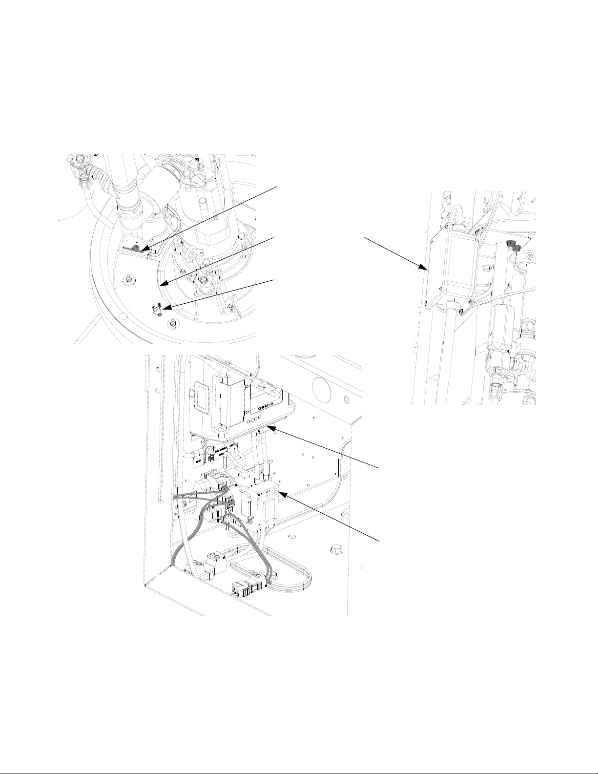
Component Identification
43A1937C
Component Identification
Kit Components
Key:
1 RTD Temperature Sensor
2HeaterCoil
3 Temperature Limit Switch
4 Junction Box
5 High Power Temperature Control Module (HPTCM)
6Relay
1
2
3
4
5
6
Component Identification
3A1937C 5
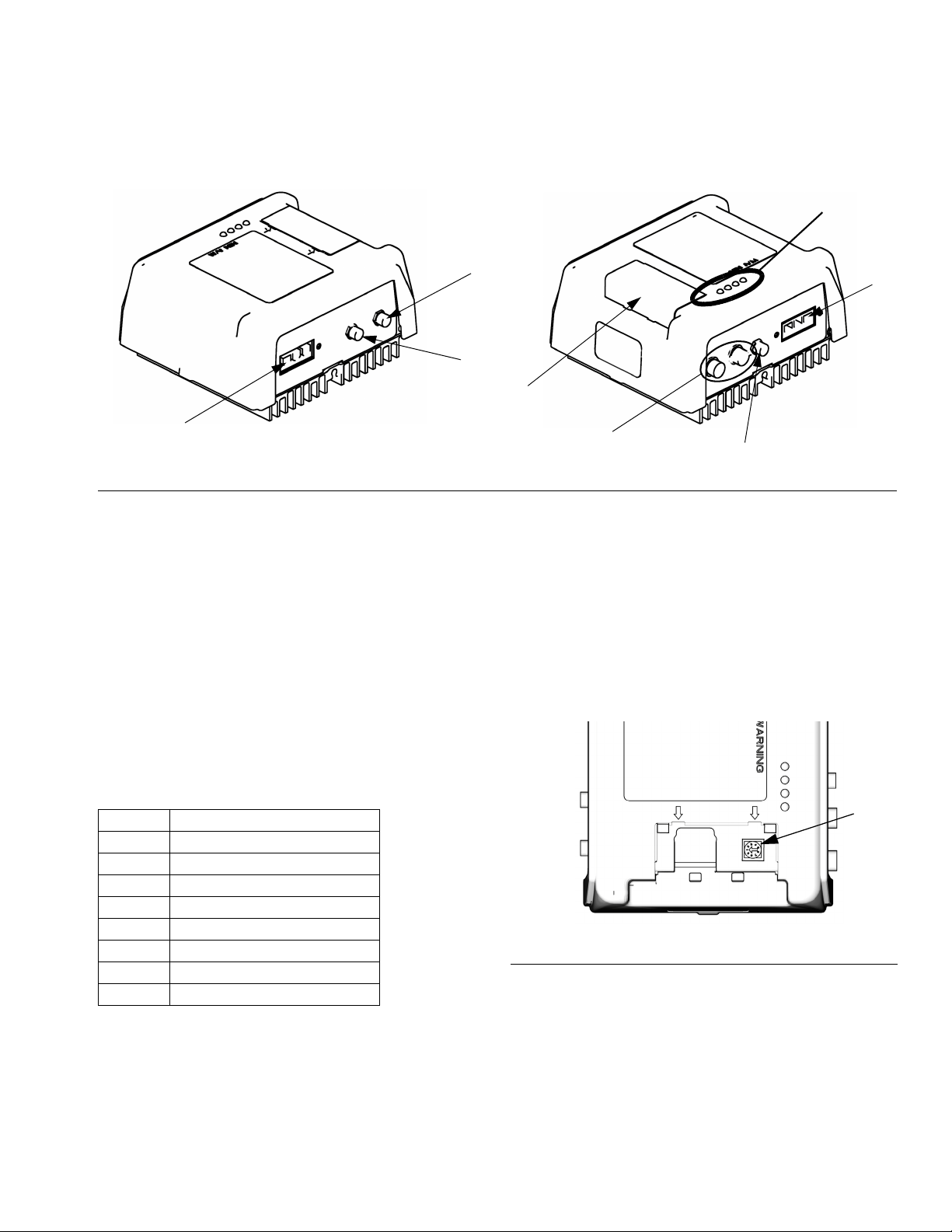
Temperature Control Module
Key:
1N/A
2 RTD Temperature Sensor Connection
3 Output Power Connection
4 DC Output Connection
5 Input Power Connection
6 CAN Connections
7 Rotary Selector Switch, Token Access
Adjust Rotary Switch
The rotary switch setting indicates which zone the tem-
perature control module will control in the system. The
high power module uses an 8-position rotary switch.
Set the rotary switch (S) to the specific selection accord-
ing to the settings listed in the following table.
FIG. 1: High Power Temperature Control Module Sensor Connections
1
2
3
5
4
6
LED
Signals
7
ti12352a1 ti12353a1
Setting Zone
0NotUsed
1 B (Blue) Primary Heat
2NotUsed
3 A (Red) Primary Heat
4NotUsed
5NotUsed
6NotUsed
7NotUsed
FIG. 2
High Power Module Rotary Switch Location
S
ti12360a
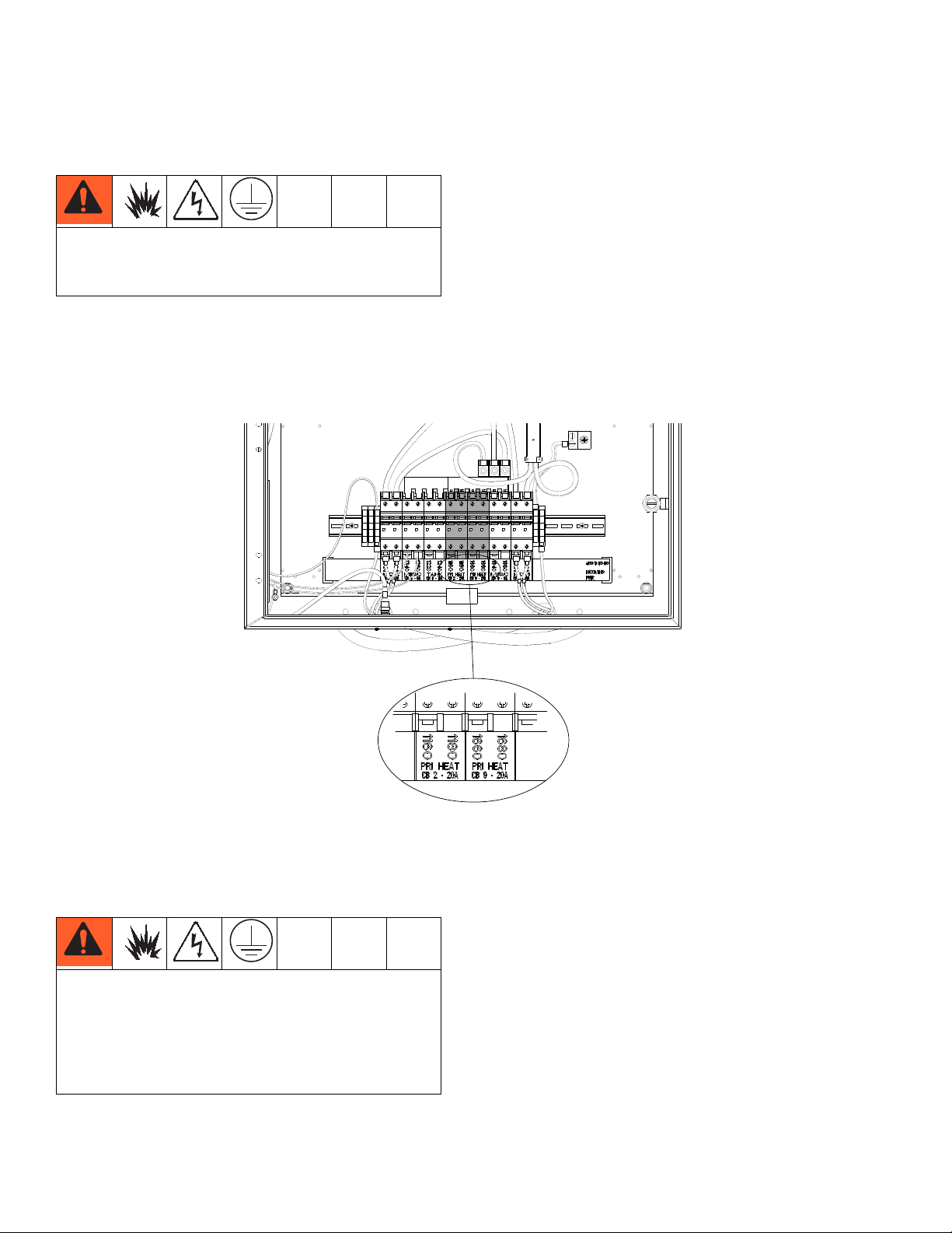
Installation
63A1937C
Installation
Power Requirements
Ensure that the electrical panel located within the Power Distribution Box has the correct circuit breakers for installing
the kit. If the current Power Distribution Box does not have this configuration, contact your local distributor inquiring
about a Power Distribution Box upgrade kit.
Grounding
Ground the system as instructed within this manual.
Setup
1. Access the Platen
a. Perform Remove Drum Procedure found in
VPM Instructions manuals.
b. Perform Shutdown Procedure found in VPM
Instructions manuals.
c. Thoroughly clean all material that may be found
on the top of the platen.
d. Turn off all sources of power to the machine.
To avoid serious injury or machine damage, all
electrical connections need to be done by a qualified
electrician familiar with local codes.
The equipment must be grounded to reduce the risk
of static sparking and electric shock. Electric or static
sparking can cause fumes to ignite or explode.
Improper grounding can cause electric shock.
Grounding provides an escape wire for the electric
current.
Installation
3A1937C 7
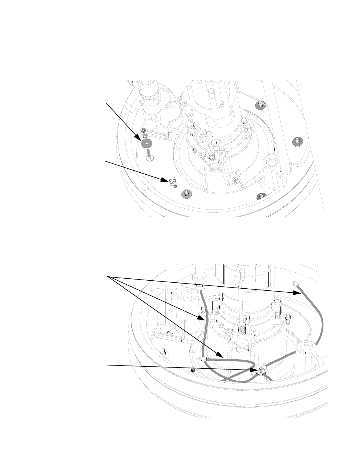
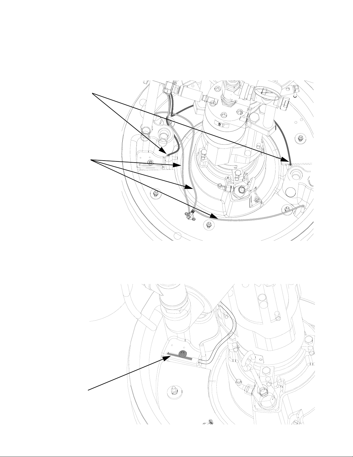
2. Install Heat Coils and Thermostat Switch
Install both heat coils onto the platen as shown below.
3. Connect Ground Wires
Connect ground wires to the terminal lug and platen covers (not shown in view). Attach conduit to platen cover (not
shown) and route wires through the conduit when connections are complete.
- (6) 1/4-20 Stud
- (6) Flat Washer
- (6) Lock Washer
- (6) Nut
- (1) Thermostat
- (2) Screws
- (3) Ground Wires
- (2) Lock Wasers
- (2) Nuts
- (1) Ground Screw
Installation
83A1937C
4. Connect Power Leads
Connect leads as shown below. Route all wires through conduit when connections are complete.
5. Mount RTD
Mount RTD as shown below. Route wire through conduit when connections are complete.
- (2) “B” Leads
- (3) “A” Leads
- (1) RTD
- (1) Washer
- (1) M5 Screw
Installation
3A1937C 9
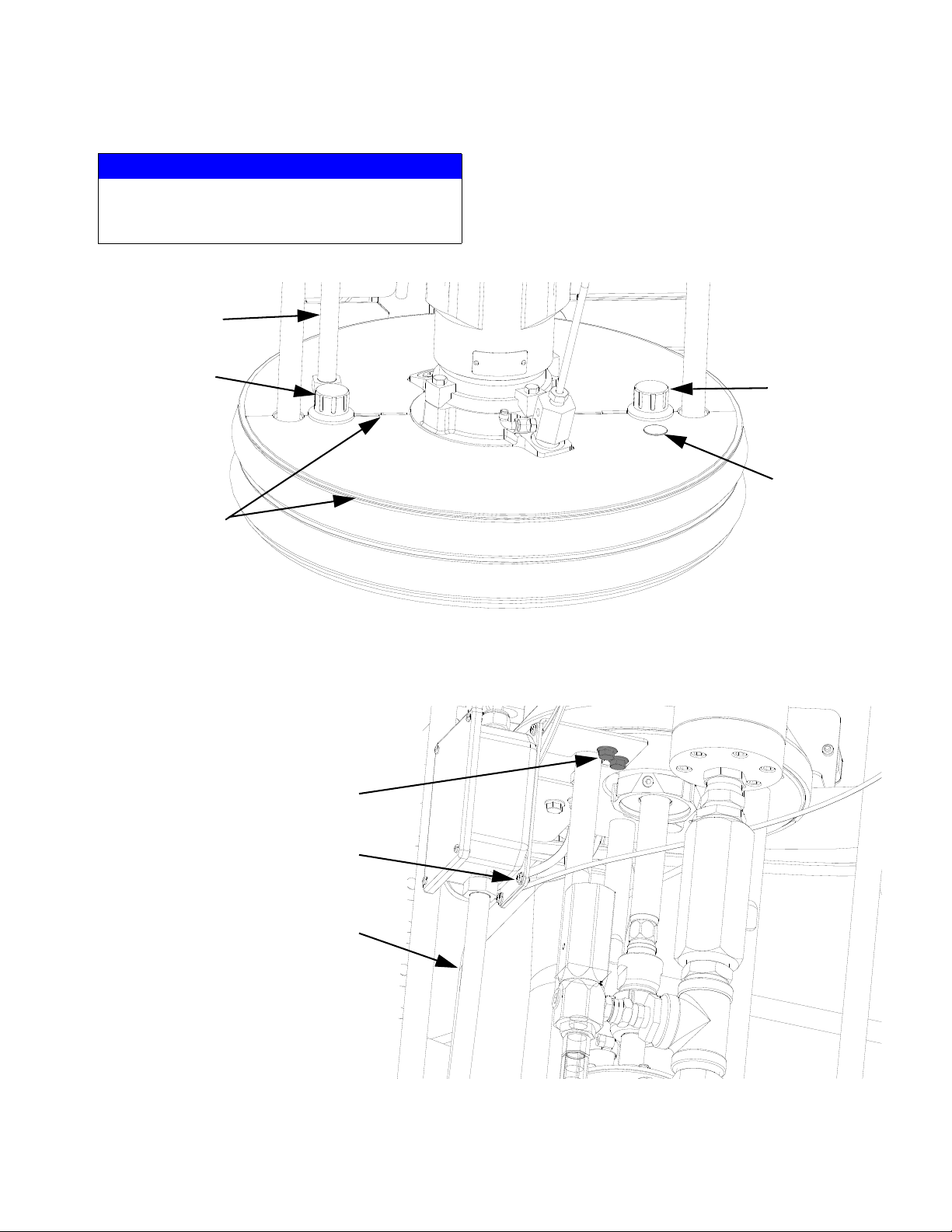
6. Attach Platen Covers
7. Mount Junction Box
NOTICE
To prevent damage to wires, ensure wires are not
pinched when assembling and securing platen cov-
ers.
- (1) Conduit
- (1) Knob
- (2) Covers
- (1) Plug
- (1) Knob
- (2) 3/8-16 Bolts
- (4) #10-32 Screws
- (4) Lock Washers
- (1) Conduit from
platen

Installation
10 3A1937C
8. Route Power Cord and Signal Cable
Route power cord and signal cable as shown below. It is recommended to start from the cube base and route to junc-
tion box.
9. Connect Leads in Junction Box
Connect “A” leads, “B” leads, ground, and signal cable within junction box.
Routing
Cord and cable to be
routed under cover
This manual suits for next models
1
Table of contents


