manuals.online logo
Brands
  1. Home
  2. •
  3. Brands
  4. •
  5. Grantech
  6. •
  7. Motherboard
  8. •
  9. Grantech SYS76989VGGA User manual

Grantech SYS76989VGGA User manual

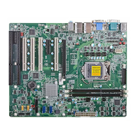
SYS76989VGGA
Industrial Computer Board
Based on the innovative Intel®QM77 chipsets for op-
timal system efciency, the board accommodates
the Intel®Core™ i7 / i5 / i3 or Celeron® proces-
sor in rPGA-989 (Socket G2) and supports 2 DDR3
1066/1333/1600 SO-DIMM slots to provide the maxi-
mum of 32GB memory capacity.
The board is durable under extreme environments
and suitable to be applied in every industrial eld, such
as digital signage, kiosk, gaming, industrial control au-
tomation and POS.
Chapter 1
Overview
1-2
Overview
▍
Motherboard Specications
CPU Intel®Core™ i7 / i5 / i3 or Celeron®processor in
rPGA-989 (Socket G2)
■
Chipset Intel®QM77 / HM76 Chipset■
Memory 2 unbuffered non-ECC DDR3 1066/1333/1600
SO-DIMM slots
Supports the maximum of 16GB
■
■
LAN Intel®82579LM Gigabit Fast Ethernet controller
Intel®WGI210AT Gigabit Fast Ethernet controller
■
■
Audio Realtek®ALC887 Codec
Compliant with Azalia 1.0 specs
■
■
RAID Supports RAID 0/ 1/ 5/ 10 (QM77)■
Graphics Graphics integrated in Intel®processor■
Back Panel
I/O
1 PS/2 mouse and keyboard combo port
4 USB 2.0 ports
1 serial port
2 DisplayPort
1 DVI-I port
2 Gigabit LAN jacks
2 USB 3.0 ports
3 exible audio ports
■
■
■
■
■
■
■
■
Onboard
Connectors/
Pinheaders
2 USB 2.0 connector
2 USB 3.0 connector
2 SATA 6Gb/s ports
2 SATA 3Gb/s ports
4 serial port connectors
2 serial port power jumpers
1 front panel pinheader
1 LVDS connector
1 LVDS power jumper
1 GPIO connector
1 clear CMOS jumper
1 AT/ATX mode select jumper
1 S/PDIF pinheader
1 chassis intrusion pinheader
1 amplier pinheader
■
■
■
■
■
■
■
■
■
■
■
■
■
■
■
1-3
Slot 2 Mini-PCIe slots (including 1 x mSATA function)■
Form Factor Mini-ITX: 17.0cm x 17.0cm
Power Solution: 12
■
■
Environ-
mental
Operating Temperature: -10oC to 60oC
Humidity: 30% ~ 80% RH, Non-Condensing
Ofce and similar emvironment, no corrosive
gas
Storage Temperature: -20oC to 80oC
Humidity: 5% ~ 90% RH, Non-Condensing
■-
-
■-
1-4
Overview
▍
Serial Port
LAN
Ports
USB 3.0
Ports
Line-In
Line-Out
MIC
Keyboard / Mouse
Combo Port
DisplayPortUSB 2.0
Ports
DisplayPort
DVI-I Port
USB 2.0
Ports
Motherboard Layout
Back Panel
Front Panel
Pinheader
USB 3.0
Connector
LVDS Connector
CPU Fan Connector
CPU Socket
Mini-PCIe Slot
COM Port Jumper
Clear CMOS Jumper
System Fan Connector
AT/ ATX Jumper
HDD Power
Connector
SO-DIMM Slots
DC Power
Connector
COM Port
Connector
USB 2.0
Connector
HDD Power
Connector
COM Port
Jumper
Chassis Intrusion
Pinheader
SATA
3Gb/s
Port
SATA
6Gb/s
Port
GPIO
Pinheader
Amplier
Pinheader
S/PDIF
Pinheader
Backlight
Pinheader &
LVDS Jumper
SATA
3Gb/s
Port
This chapter provides you with the information on
motherboard hardware congurations. Incorrect set-
ting of jumpers and connectors may damage your
motherboard. Please pay special attention not to con-
nect these headers in wrong direction. DO NOT adjust
any jumper while the motherboard is powered on.
Chapter 2
Hardware Setup
2-2
Hardware Setup
▍
Quick Components Guide
Back Panel,
p.2-7
JFP1, p.2-10
J1, p.2-13
JLVDS1, p.2-14
CPUFAN1, p.2-9
CPU, p.2-3
SLOT1, p.2-17
JCOMP2, p.2-16
JCMOS1, p.2-15
SYSFAN1, p.2-9
JATX1, p.2-15
JPW1, p.2-6
DIMM1/2,
p.2-5
DCPWR1/2,
p.2-6
COM2~4,
p.2-12
JUSB1, p.2-13
JPW2, p.2-6
JCOMP1,
p.2-16
JCASE1, p.2-10
SATA3,
p.2-9
SATA1/2,
p.2-9
JGPIO1,
p.2-11
JAMP1,
p.2-11
JSPDI1,
p.2-11
JLCD1, p.2-16
SATA4,
p.2-9
2-3
CPU (Central Processing Unit)
When you are installing the CPU, make sure that you install the cooler
to prevent overheating. If you do not have the CPU cooler, consult your
dealer before turning on the computer.
Important
Overheating
Overheating can seriously damage the CPU and motherboard. Always
make sure the cooling fans work properly to protect the CPU from over-
heating. Be sure to apply an even layer of thermal paste (or thermal tape)
between the CPU and the heatsink to enhance heat dissipation.
Replacing the CPU
When replacing the CPU, always turn off the system’s power supply and
unplug the power supply’s power cord to ensure the safety of the CPU.
2-4
Hardware Setup
▍
CPU Installation
Locate the CPU socket on the motherboard. On the upper end of the CPU
socket is a socket actuator in the form of a slotted screw head.
To install the CPU, follow the steps shown below:
1. Loosen the socket actuator
with a parallel screwdriver.
2. Locate Pin 1 in the socket and look for a golden cut edge on the
CPU upper corner. Then insert the CPU into the socket. To avoid
damaging the CPU pins, do not force the CPU into the socket.
3. Fasten the CPU socket with
a parallel screwdriver.
Important
Motherboard photos shown in
this section are for demonstration
only and may differ from the ac-
tual look of your motherboard.
2-5
Memory
These DIMM slots are intended for memory modules.
1. Unlock the DIMM slot by
ipping open its side clips.
Vertically insert the DIMM
into the DIMM slot. The
DIMM has an off-center
notch at the bottom that will
only allow it to t one way
into the DIMM slot.
2. Push the DIMM deeply into
the DIMM slot. The side
clips of the DIMM slot will
automatically close when
the DIMM is properly seated
and an audible click should
be heard.
3. Manually check if the DIMM
has been locked in place by
the DIMM slot’s side clips.
Important
Motherboard photos shown
in this section are for demon-
stration only and may differ
from the actual look of your
motherboard.
You can barely see the golden
nger if the DIMM is properly
inserted in the DIMM slot.
•
•
2-6
Hardware Setup
▍
Power Supply
4-pin Power Connector: DCPWR1, DCPWR2
These connectors are used to provide power to the motherboard.
4.+12V
2.Ground
3.+12V
1.Ground
HDD Power Connector: JPW1, JPW2
This connector is used to provide power for hard disk drives.
2.GND
3.GND
1.VCC5
4.C12V
Important
Make sure that all the connectors are connected to proper power supplies
to ensure stable operation of the motherboard.
2-7
Back Panel I/O
Serial Port
LAN
Ports
USB 3.0
Ports
Line-In
Line-Out
MIC
Keyboard / Mouse
Combo Port
DisplayPortUSB 2.0
Ports
DisplayPort
DVI-I Port
USB 2.0
Ports
Keyboard / Mouse Combo Port
The standard PS/2®mouse/keyboard DIN connector is for a PS/2®
mouse/keyboard.
Serial Port
The serial port is a 16550A high speed communications port that sends/
receives 16 bytes FIFOs. You can attach a serial mouse or other serial
devices directly to the connector.
DisplayPort
DisplayPort is a digital display interface standard. This connector is used
to connect a monitor with DisplayPort inputs.
DVI-I Port
The DVI-I (Digital Visual Interface-Integrated) connector allows you to
connect an LCD monitor. It provides a high-speed digital interconnection
between the computer and its display device. To connect an LCD monitor,
simply plug your monitor cable into the DVI connector, and make sure that
the other end of the cable is properly connected to your monitor (refer to
your monitor manual for more information.)
USB 2�0 Port
The USB (Universal Serial Bus) port is for attaching USB devices such as
keyboard, mouse, or other USB-compatible devices.
▶
▶
▶
▶
▶
2-8
Hardware Setup
▍
USB 3�0 Port
The USB 3.0 port is backward-compatible with USB 2.0 devices and sup-
ports data transfer rate up to 5 Gbit/s (SuperSpeed).
LAN Port
The standard RJ-45 LAN jack is for connection to the Local Area Network
(LAN). You can connect a network cable to it.
Speed IndicatorActivity Indicator
Left LED Right LED
Active LED 100M/1000M Speed LED
LED Color Yellow Green/Orange
10M Cable
Plug-in
No Transmission OFF OFF
Transmission Yellow (Blinking) OFF
100M Cable
Plug-in
No Transmission OFF Green (Lighting)
Transmission Yellow (Blinking) Green (Lighting)
1000M Cable
Plug-in
No Transmission OFF Orange (Lighting)
Transmission Yellow (Blinking) Orange (Lighting)
In S3/S4/S5 Standby State OFF OFF
Audio Ports
These audio connectors are used for audio devices. It is easy to differenti-
ate between audio effects according to the color of audio jacks.
Line-In (Blue) - Line In, is used for external CD player, tapeplayer
or other audio devices.
Line-Out (Green) - Line Out, is a connector for speakers or head-
phones.
Mic (Pink) - Mic, is a connector for microphones.
▶
▶
▶
■
■
■
2-9
Connector
Serial ATA Connector: SATA1 ~ SATA4
This connector is a high-speed Serial ATA interface port. Each connector
can connect to one Serial ATA device.
Chip SATA 6 Gb/s SATA 3 Gb/s
Intel QM77 SATA1, SATA2 SATA3, SATA4
Important
Please do not fold the Serial ATA cable into a 90-degree angle. Other-
wise, data loss may occur during transmission.
Fan Power Connector: CPUFAN1, SYSFAN1
The fan power connectors support system cooling fan with +12V. When
connecting the wire to the connectors, always note that the red wire is the
positive and should be connected to the +12V; the black wire is Ground
and should be connected to GND. If the motherboard has a System Hard-
ware Monitor chipset on-board, you must use a specially designed fan
with speed sensor to take advantage of the CPU fan control.
1.Ground
2.+12V
3.Sensor
Important
Please refer to the recommended CPU fan at processor’s ofcial website
or consult the vendors for proper CPU cooling fan.
2-10
Hardware Setup
▍
Chassis Intrusion Pinheader: JCASE1
This connector connects to the chassis intrusion switch cable. If the com-
puter case is opened, the chassis intrusion mechanism will be activated.
The system will record this intrusion and a warning message will ash on
screen. To clear the warning, you must enter the BIOS utility and clear
the record.
1.CINTRU
2.Ground
Front Panel Pinheader: JFP1
These connectors are for electrical connection to the front panel switches
and LEDs. The JFP1 is compliant with Intel®Front Panel I/O Connectivity
Design Guide.
1.+
3.-
10.No Pin
5.-Reset S
witch
HDD LE
D
P
ower Switch
Power LED
7.+
9.Reserved
8.-
6.+
4.-
2.+
2-11
Audio Amplier Pinheader: JAMP1
The JAMP1 is used to connect audio ampliers to enhance audio per-
formance.
2.AMP_L+
1.AMP_L4
4.AMP_R+
3.AMP_R4
S/PDIF Pinheader: JSPDI1
This pinheader is used to connect S/PDIF (Sony & Philips Digital Inter-
connect Format) interface for digital audio transmission.
2.SPDIF
3.GN
D
1.GC
C
GPIO Pinheader: JGPIO1
This connector is provided for the General-Purpose Input/Output (GPIO)
peripheral module.
8.N_GPI1
6.N_GPI2
4.N_GPI6
1.GND
6.N_GPO6
10.N_GPI
0
5.N_GPO2
7.N_GPO1
9.N_GPO
0
2.VCC5
2-12
Hardware Setup
▍
Serial Port Connector: COM2, COM3, COM4
This connector is a 16550A high speed communications port that sends/
receives 16 bytes FIFOs. You can attach serial devices to it through the
optional serial port bracket.
8.CTS
3.TXD
1.DCD
6.DSR
5.GND
4.DTR
7.RTS
2.RXD
9.VCC_COM
PIN SIGNAL DESCRIPTION
1
2
3
4
5
6
7
8
9
DCD
RXD
TXD
DTR
GND
DSR
RTS
CTS
VCC_COM1
Data Carrier Detect
Receive Data
Transmit Data
Data Terminal Ready
Signal Ground
Data Set Ready
Request To Send
Clear To Send
Voltage select setting by jumper
RS-232
2-13
Front USB 2�0 Connector: JUSB1
This connector, compliant with Intel I/O Connectivity Design Guide, is
ideal for connecting high-speed USB interface peripherals such as USB
HDD, digital cameras, MP3 players, printers, modems and the like.
8.G N D
3.USB10B
1.Power
6.USB11+
5.USB10+
4.USB11B
7.G N D
2.Power
Important
Note that the pins of VCC and GND must be connected correctly to avoid
possible damage.
Front USB 3�0 Connector: J1
The USB 3.0 connector is backwards compatible with USB 2.0 devices.
It supports data transfer rates up to 5Gbits/s (SuperSpeed) and is ideal
for connecting high-speed USB peripherals such as USB HDDs, digital
cameras, MP3 players, printers, modems, and many others.
5.USB1_TX_C_DN
4.Ground
1.USB1_RX_DP
2.USB1_RX_DN
1.Power
10.NC
9. +USB2.0
8. -USB2.0
7.Ground
6.USB1_TX_C_DP
20.No
Pin
19.Power
18.USB1_RX_DN
17.USB1_RX_DP
16.Ground
15.USB1_TX_C_DN
14.USB1_TX_C_DP
11.Ground
12.USB2.0 -
11. +USB2.0
Important
Note that the pins of VCC and GND must be connected correctly to avoid
possible damage.
2-14
Hardware Setup
▍
LVDS Flat Panel Connector: JLVDS1
The LVDS (Low Voltage Differential Signal) connector provides a digital
interface typically used with at panels. After connecting an LVDS inter-
faced at panel to the JLVDS1, be sure to check the panel datasheet and
set the J2 jumper for proper power voltage.
39.LVDSB_CLK#C
27.LVDSB_DATAC#1
25.LVDSB_DATAC1
23.GND
21.LVDSA_DATAC#3
19.LVDSA_DATAC3
17.GND
15.LVDSA_DATAC#1
13.LVDSA_DATAC1
11.LVDS_BLON
9.L_BKLT_CTRL#
7.LVDS_DDC_CLK
5.LCD_VDD
3.NC
1.+12V
40.
LVDSA_CLK#C
28.LVDSB_DATAC#0
26.
LVDSB_DATAC0
24.GND
22.LVDSA_DATAC#2
20.LVDSA_DATAC2
18.GND
16.LVDSA_DATAC#0
14.LVDSA_DATAC0
12.GND
10.LVDS_VDD_EN
8.LVDS_DDC_DATA
6.LCD_VDD
4.+12V
2.+12V
37.LVDSB_CLKC
35.GND
33.LVDSB_DATAC#3
31.LVDSB_DATAC3
29.GND
38.LVDSA_CLKC
36.GND
34.LVDSB_DATAC#2
32.LVDSB_DATAC2
30.GND
2-15
Jumper
Clear CMOS Jumper: JCMOS1
There is a CMOS RAM onboard that has a power supply from an external
battery to keep the data of system conguration. With the CMOS RAM,
the system can automatically boot OS every time it is turned on. If you
want to clear the system conguration, set the jumper to clear data.
Keep Data
JCMOS1 Clear CMOS
1
1
1
Important
You can clear CMOS by shorting 1-2 pin while the system is off. Then
return to 2-3 pin position. Avoid clearing the CMOS while the system is
on; it will damage the motherboard.
AT/ATX Select Jumper: JATX1
This jumper allows users to select between AT and ATX power.
ATX
JATX1 AT
1
1
1
Important
Avoid adjusting the jumper when the system is on; it will damage the
motherboard.

Other Grantech Motherboard manuals

Grantech SYS86366VGGA-10C User manual

Grantech

Grantech SYS86366VGGA-10C User manual

Grantech SYS8F377VGGA-3OM User manual

Grantech

Grantech SYS8F377VGGA-3OM User manual

Grantech SYS86366VGGA-10C User manual

Grantech

Grantech SYS86366VGGA-10C User manual

Grantech SYS86350V4GA User manual

Grantech

Grantech SYS86350V4GA User manual

Grantech SYM86370VGGA User manual

Grantech

Grantech SYM86370VGGA User manual

Grantech SYS8F360VGGA User manual

Grantech

Grantech SYS8F360VGGA User manual

Grantech SYS76992VGGA User manual

Grantech

Grantech SYS76992VGGA User manual
Grantech SYS8F377VGGA-3OMN User manual

Grantech

Grantech SYS8F377VGGA-3OMN User manual

Grantech SYM76999VGGA User manual

Grantech

Grantech SYM76999VGGA User manual

Grantech SYS86355VGGA-E User manual

Grantech

Grantech SYS86355VGGA-E User manual

Grantech SYS86355VGGA-6C User manual

Grantech

Grantech SYS86355VGGA-6C User manual

Grantech SYM76941VGGA User manual

Grantech

Grantech SYM76941VGGA User manual

Grantech SYS86355VGGA-6 User manual

Grantech

Grantech SYS86355VGGA-6 User manual

Grantech SYM86455VG GA User manual

Grantech

Grantech SYM86455VG GA User manual

Grantech SYS76866VGGA-525-NM User manual

Grantech

Grantech SYS76866VGGA-525-NM User manual

Grantech SYS8F361VGGA Series User manual

Grantech

Grantech SYS8F361VGGA Series User manual

Grantech SYM86360V4GA User manual

Grantech

Grantech SYM86360V4GA User manual

Grantech 6601VGGA-H310 User manual

Grantech

Grantech 6601VGGA-H310 User manual

Grantech SYM76990VGGA-SP User manual

Grantech

Grantech SYM76990VGGA-SP User manual

Grantech SYS76877VGGA-E User manual

Grantech

Grantech SYS76877VGGA-E User manual

Grantech SYM76993VGGA User manual

Grantech

Grantech SYM76993VGGA User manual

Grantech SYM86368VGGA User manual

Grantech

Grantech SYM86368VGGA User manual

Grantech SYM86349VGGA User manual

Grantech

Grantech SYM86349VGGA User manual
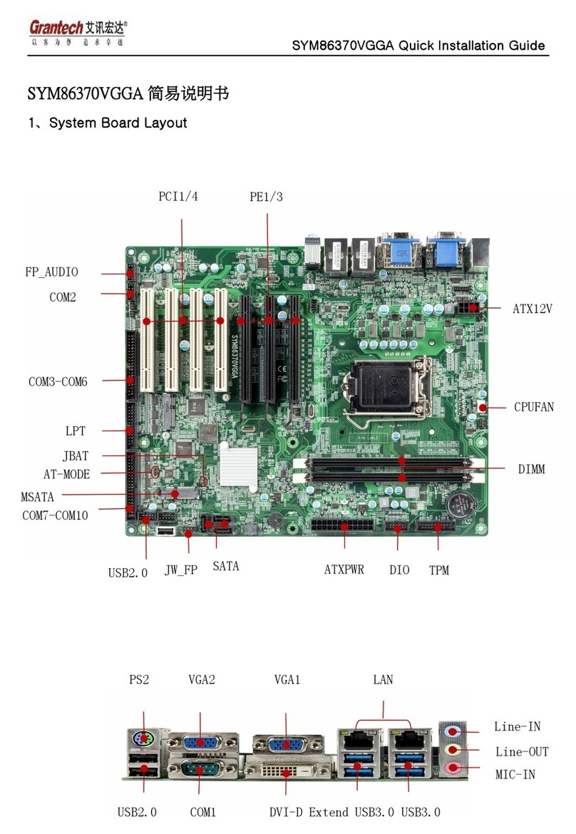
Grantech SYM86370VGGA User manual

Grantech

Grantech SYM86370VGGA User manual
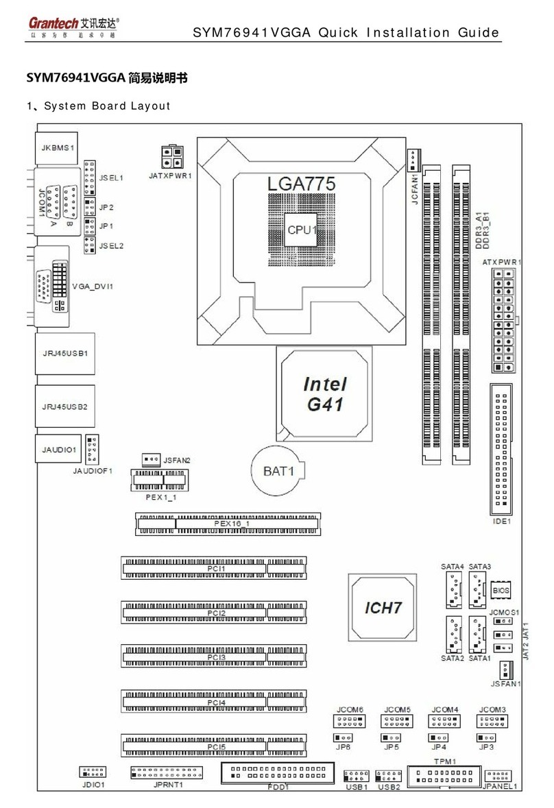
Popular Motherboard manuals by other brands

Embedded Systems LogicMachine5 datasheet

Embedded Systems

Embedded Systems LogicMachine5 datasheet

Cypress S6SBP401AJ0SA1001 manual

Cypress

Cypress S6SBP401AJ0SA1001 manual

Colorful BATTLE-AX B760M-D PRO V20 user manual

Colorful

Colorful BATTLE-AX B760M-D PRO V20 user manual

Indel GIN-SAM3 quick start guide

Indel

Indel GIN-SAM3 quick start guide

IEI Technology NANO-GX2 user manual

IEI Technology

IEI Technology NANO-GX2 user manual

A-Trend ATC-6400 manual

A-Trend

A-Trend ATC-6400 manual

DFI TGU171 user manual

DFI

DFI TGU171 user manual

Texas Instruments LMG2100 user guide

Texas Instruments

Texas Instruments LMG2100 user guide

ASROCK P55M PRO - brochure

ASROCK

ASROCK P55M PRO - brochure

Gigabyte GA-6VM7-4X user manual

Gigabyte

Gigabyte GA-6VM7-4X user manual

ASROCK 90-MXB150-A0UAYZ user manual

ASROCK

ASROCK 90-MXB150-A0UAYZ user manual

Biostar X470GTA manual

Biostar

Biostar X470GTA manual

ASROCK FM2A75 PRO04+ user manual

ASROCK

ASROCK FM2A75 PRO04+ user manual

Linear Technology DC2164A-A manual

Linear Technology

Linear Technology DC2164A-A manual

Avalue Technology EAX-C246P-B1 user manual

Avalue Technology

Avalue Technology EAX-C246P-B1 user manual

AXIOMTEK SBC86831 Series user manual

AXIOMTEK

AXIOMTEK SBC86831 Series user manual

ASROCK P43DE3 brochure

ASROCK

ASROCK P43DE3 brochure

STMicroelectronics STM32G081B-EVAL user manual

STMicroelectronics

STMicroelectronics STM32G081B-EVAL user manual

manuals.online logo
manuals.online logoBrands
  • About & Mission
  • Contact us
  • Privacy Policy
  • Terms and Conditions

Copyright 2025 Manuals.Online. All Rights Reserved.