Greenlee Power Finder 2007 Instruction Manual
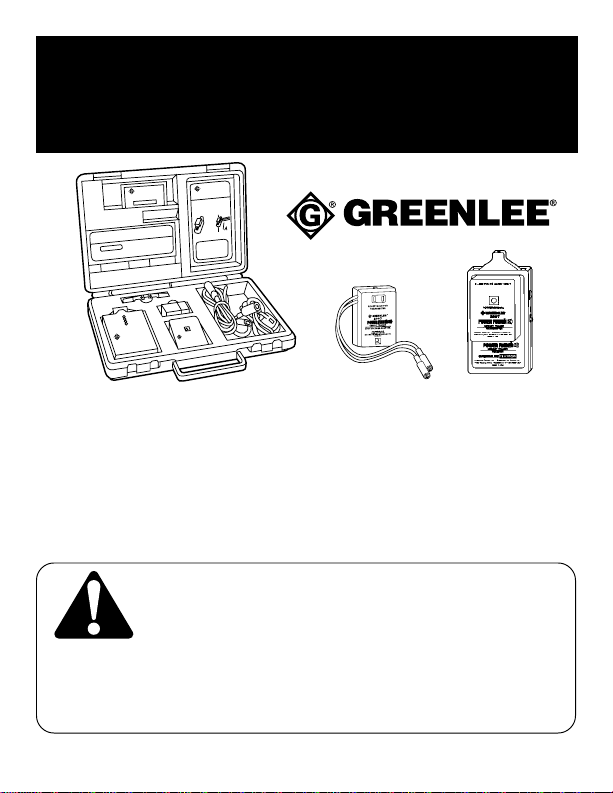
2007 POWER FINDER™ CIRCUIT TRACER
AND 38583 HIGH VOLTAGE ADAPTER
DÉTECTEUR DE CIRCUIT POWER FINDERMC 2007
ET ADAPTATEUR HAUTE TENSION 38583
RASTREADOR DE CIRCUITOS POWERFINDERMR 2007
Y ADAPTADOR DE ALTO VOLTAJE 38583
999 0380.6 ©1996 Greenlee Textron Inc. IM-1123 REV 2 9/96
INSTRUCTION & SAFETY MANUAL
MANUEL D’INSTRUCTIONS ET DE SÉCURITÉ
MANUAL DE INSTRUCCIONES Y SEGURIDAD
Read and understand this material before operating or servicing the circuit tracer. Failure to
understand how to safely operate the circuit tracer could result in an accident causing serious
injury or death. This tool should only be operated by qualified personnel.
Assurez-vous que vous avez lu et compris la documentation avant d’utiliser ou de faire
l’entretien de ce détecteur de circuit. Si vous ne comprenez pas comment utiliser le détecteur
de circuit en toute sécurité, vous pourriez provoquer un accident entraînant des blessures graves, voire mortelles. Cet
outil ne doit être utilisé que par un personnel qualifié.
Leer y comprender este material antes de operar o prestar mantenimiento al rastreador de circuitos. La falta de
comprensión acerca de cómo operar con seguridad el rastreador de circuitos puede ocasionar un accidente que
cause lesiones graves o muerte. Esta herramienta debe ser operada solamente por personal calificado.
GREENLEE
GREENLEE
GREENLEE
GREENLEE

2007 POWER FINDER™ Circuit Tracer
2
Greenlee Textron Inc. / Subsidiary of Textron Inc. 4455 Boeing Dr., Rockford, IL 61109-2988 USA 815/397-7070
INDEX
Introduction ..................................................................................... 2
Safety Alert Symbol ........................................................................ 3
What the PowerFinder™ Will Do.................................................... 4
How the PowerFinder™ Operates ................................................. 5
How to Trace Live Circuits.........................................................6-13
How to Trace Dead and Shorted Circuits................................14-17
PowerFinder™ High Voltage Adapter .......................................... 18
Specifications................................................................................ 19
Warranty Information .................................................................... 20
French Version.............................................................................. 21
Spanish Version............................................................................ 40
INTRODUCTION
The PowerFinder™ Circuit Tracer is designed to be used by experi-
enced, trained electrical workers to identify and/or trace circuits. This
requires that the transmitter be integrated into the circuit being traced
or identified and that the circuit is powered by 9 to 300 voltsAC or DC
(680 VAC or 1000 VDC when using the 38583 High VoltageAdapter).
The transmitter is designed to plug into a standard 120 V outlet. For
all other uses, a transmitter plug adapter with alligator clips and
attachable receptacle blades are included.

2007 POWER FINDER™ Circuit Tracer
3
Greenlee Textron Inc. / Subsidiary of Textron Inc. 4455 Boeing Dr., Rockford, IL 61109-2988 USA 815/397-7070
SAFETY ALERT SYMBOL
The symbol above is used to call your attention to instructions
concerning your personal safety. Watch for this symbol. It points out
important safety precautions. It means “ATTENTION! Become Alert!
Your personal safety is involved!”Read the message that follows
and be alert to the possibility of personal injury or death.
Immediate hazards which WILL result in severe personal injury
or death.
Hazards or unsafe practices which COULD result in severe
personal injury or death.
Hazards or unsafe practices which COULD result in minor personal
injury or property damage.
SAVETHESE INSTRUCTIONS!
Additional copies of this manual are available
upon request at no extra charge.
2007 POWER FINDER™ Circuit Tracer
4
Greenlee Textron Inc. / Subsidiary of Textron Inc. 4455 Boeing Dr., Rockford, IL 61109-2988 USA 815/397-7070
Read and understand all operating and
safety instructions before using this tracer.
Failure to read and understand instructions
may result in electrocution and death.
WHATTHE POWERFINDER™ WILL DO
NOTE: All examples of circuit connections are shown in Sections
3 and 4.
The Greenlee PowerFinder™ circuit tracer will find:
CIRCUIT BREAKERS
FUSES
POWER PANELS
LIGHTING PANELS
JUNCTION BOXES
SHORTS TO GROUND
With the PowerFinder™ you can trace HOT, NEUTRAL and
GROUND WIRES IN WALLS, IN CONDUIT and UNDER-
GROUND.

2007 POWER FINDER™ Circuit Tracer
5
Greenlee Textron Inc. / Subsidiary of Textron Inc. 4455 Boeing Dr., Rockford, IL 61109-2988 USA 815/397-7070
HOWTHE POWERFINDER™ OPERATES
The PowerFinder is composed of two primary components:
the receiver and the transmitter. When the transmitter is
plugged into any 9-300 VoltAC or DC source (680 VAC or
1000 VDC when using the 38583 High Voltage Adapter), it
draws a very small current (8-100 mA) in a very unique
manner: the current drawn is a crystal-controlled, precision
combination of four separate frequencies. This composite
signal gives it a specialized Signature.
To be received, the signal must have this exact combination
of frequencies.
This feature greatly reduces the possibility of interference
from electrical noise, which is often caused by lamps,
appliances, fluorescent fixtures, or machinery that is sup-
plied by the same power source as the circuit being traced.
The current drawn by the transmitter generates a magnetic
field signature around the conductor being traced which
matches the current itself. This magnetic signature is
present the entire length of the current path, including
through breakers, fuses, switchgear, and transformers.
The PowerFinder™ receiver is tuned to pick up only that
magnetic signature produced by the transmitter.
2007 POWER FINDER™ Circuit Tracer
6
Greenlee Textron Inc. / Subsidiary of Textron Inc. 4455 Boeing Dr., Rockford, IL 61109-2988 USA 815/397-7070
Prior to plugging the transmitter into the circuit to be traced,
use an approved voltage tester, such as the Greenlee 6706,
6708, or 6709, to determine the voltage present. If the voltage
is less than 300 volts AC or DC, you may continue.
HOW TO TRACE LIVE CIRCUITS
IMPORTANT
Do not connect the PowerFinder to power in excess of 300
volts! Connecting to more than 300 volts will cause damage to
the unit.
NOTE: For circuits other than 120 volts, use the accessory leads
provided with the unit.
Following are examples of possible connections:
EXAMPLE 1
Connection to a live 120 volt receptacle
(one with voltage present)
1) Plug the transmitter into the receptacle. The Green LED light
will blink intermittently.
2) Place the receiver RANGE switch in the HIGH position. Turn
the GAIN knob ON by rotating in a clockwise position (when
facing the front of the receiver).

2007 POWER FINDER™ Circuit Tracer
7
Greenlee Textron Inc. / Subsidiary of Textron Inc. 4455 Boeing Dr., Rockford, IL 61109-2988 USA 815/397-7070
The green POWER LED will glow. (If it doesn’t, remove and
replace the 9 volt battery, which is accessed by sliding the small
battery door on the rear of the receiver to the open position).
Continue to move the GAIN knob in the clockwise direction until
it has reached its maximum travel. Move the receiver to within a
few inches of the transmitter. All 4 red LEDs will intermittently
glow, and the unit will emit a beeping sound. The 2007 is now
ready to operate.
3) Take the receiver to the vicinity of the suspected power source
for the circuit being tested. If a signal is received, move the
receiver toward the equipment, producing the increase in signal
strength. (The receiver will pick up a signal within 12 to 18
inches of a panel, even with the panel cover closed).
4) If the signal is present, open the door, position the RANGE
switch to LOW and move the receiver slowly down the row of
breakers or fuses as shown below.
NOTE:
The receiver
must be held in the
position shown here to
be properly aligned
with the magnetic field
produced by the
transmitter and provide
maximum performance.

2007 POWER FINDER™ Circuit Tracer
8
Greenlee Textron Inc. / Subsidiary of Textron Inc. 4455 Boeing Dr., Rockford, IL 61109-2988 USA 815/397-7070
5) If the signal is strong enough to cause all 4 red LEDs to glow,
the GAIN knob should be rotated in a counterclockwise
direction until only 2 or 3 LEDs are lit. Lowering the GAIN
permits the 2007 to zero-in on the only hot wire or neutral of the
circuit being tested.
NOTE: Since any wire carrying the load from the transmitter
will have the magnetic signature around it, both the hot and the
neutral will carry the signal.
6) The breaker or fuse providing the strongest signal (lighting the
most LEDs) is the one powering the transmitter, and hence, the
receptacle or device to which it is connected.
If there is any doubt as to which is the correct breaker of fuse
(due to unusual breaker design, wiring, or the possibility that
two breakers are feeding the same circuit) remove the panel
trim and check the wires.
NOTE: If the hot and neutral are close together as in a conduit
or multi-conductor cable, the electrical signals tend to cancel
each other out. Although the PowerFinder receiver is sensitive
enough to trace the signal at short distances from the conduit
or cable in question, maximum distance is acquired by separat-
ing the current paths.
“Separating the current paths” simply means drawing current
through the cable or conduit in one direction by using a remote
ground path as shown in the following diagram.

2007 POWER FINDER™ Circuit Tracer
9
Greenlee Textron Inc. / Subsidiary of Textron Inc. 4455 Boeing Dr., Rockford, IL 61109-2988 USA 815/397-7070
By creating a separate ground path, it is possible to trace wiring
from up to 20 feet away. When tracing cable in this manner, the
receiver should be held as shown below.
®®
®
TM
2007 POWER FINDER™ Circuit Tracer
10
Greenlee Textron Inc. / Subsidiary of Textron Inc. 4455 Boeing Dr., Rockford, IL 61109-2988 USA 815/397-7070
EXAMPLE 2
Connection to a live receptacle supplied by more than 120 volts
(208, 220, 230, 240, etc.)
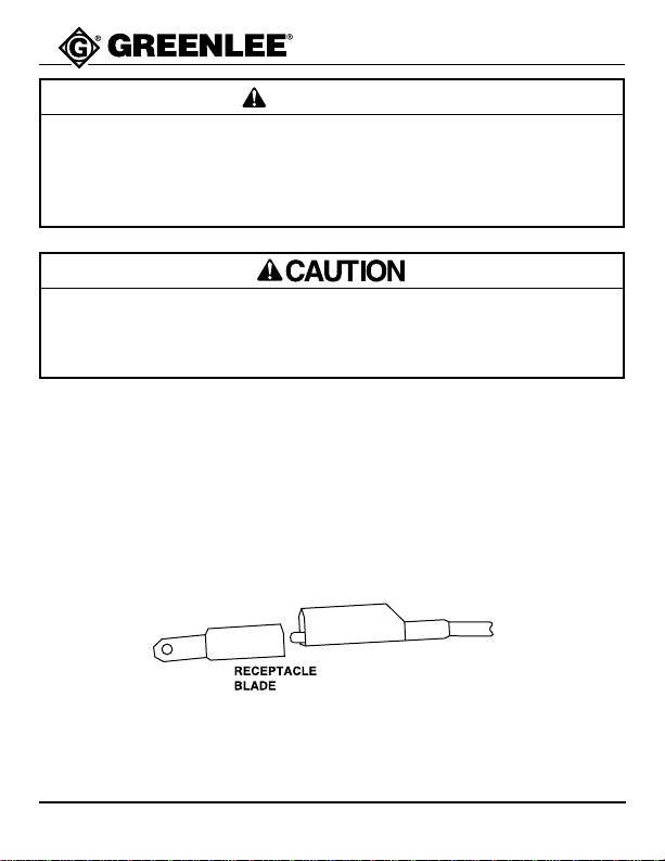
1) Using the transmitter adapter plug, connect one alligator clip to
one of the receptacle blades by opening the clip slightly and
fastening it to the small prong inside the round portion of the
receptacle blade.
Connect the other alligator clip to the other receptacle blade in
the same fashion.
Prior to plugging the transmitter into the circuit to be traced,
use an approved voltage tester, such as the Greenlee 6706,
6708, or 6709, to determine the voltage present. If the voltage
is less than 300 volts AC or DC, you may continue.
Do not connect the PowerFinder to power in excess of 300
volts! Connecting to more than 300 volts will cause damage to
the unit.
IMPORTANT
This manual suits for next models
1
Table of contents
Languages:
Other Greenlee GPS manuals


