Hydraulic Pruners
Greenlee / A Textron Company 4455 Boeing Dr. • Rockford, IL 61109-2988 USA • 815-397-7070
8
Maintenance
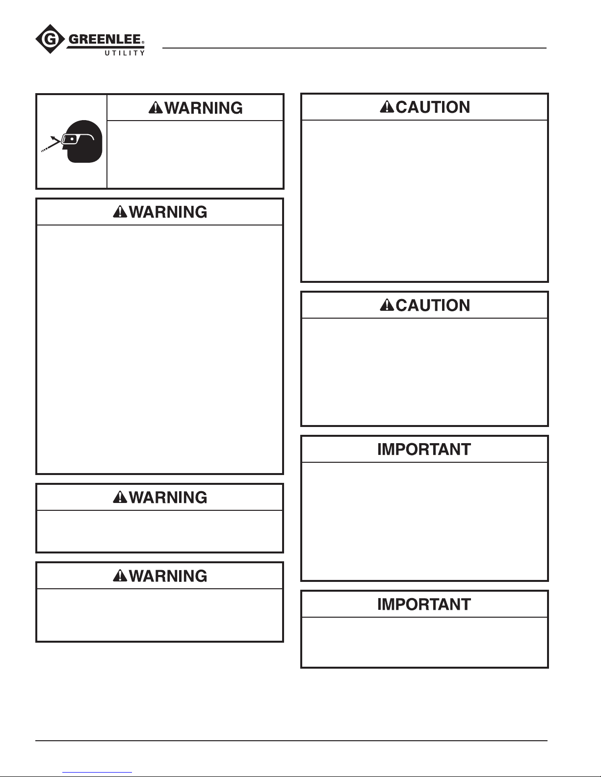
Wear eye protection when operating
or servicing this tool.
Failure to wear eye protection can
result in serious eye injury from
ying debris or hydraulic oil.
Do not dress the blade or inspect, adjust or clean
tool when it is connected to a power source.
Accidental start-up can result in serious injury.
Failure to observe these warnings can result in
severe injury or death.
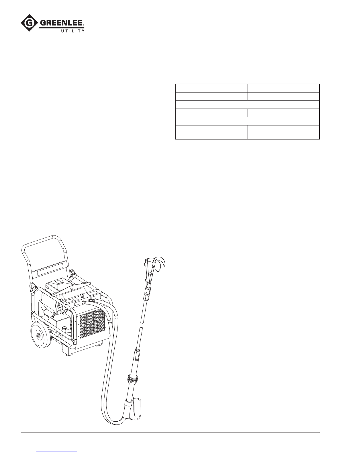
SCHEDULE
Use this schedule to maximize the tool’s service life.
Notes:
• Keep all decals clean and legible. Replace decals
when necessary. See the Specifications and Parts
manual for decal part numbers.
• When disposing of any components (hydraulic hoses,
hydraulic fluid, worn parts, etc.), do so in accordance
with federal, state and local laws or ordinances.
Daily
1. Wipe all tool surfaces clean.
48520: Use any approved berglass cleaning
products on the berglass extension. Do not use
solvents or gasoline for cleaning the fiberglass
extension.
2. Inspect the cutter unit. Check for wear at the pivot-
ing and sliding surfaces. Sharpen the blade as
instructed under Blade and Hook Maintenance.
Remove and destroy any blade with cracks,
chips or gouges.
3. Check the extension tube connector nut and the
cutter mounting bracket bolts to be sure they are
tightened securely.
4. Inspect the hydraulic hoses and ttings for signs
of leaks, cracks, wear or damage. Replace if
necessary.
5. Install dust caps over the hydraulic ports when the
tool is disconnected.
Monthly
Perform a thorough inspection of the hydraulic hoses
and ttings as described in publication 99930323,
SAE J1273 (Hose and Hose Assemblies).
Annually
If required by your organization’s regulations, have the
tool inspected by an authorized Greenlee Utility service
center.
DRESSING THE BLADE AND HOOK
A buildup of metal, called wire edge, forms at the edge
of a new blade as it seats across the face of the hook.
This wire edge must be removed several times, until the
blade seats itself to the hook.
Rough and dull edges may form on the blade and hook
from normal use. Both components must be dressed
with a whetstone several times daily. This keeps the
cutting edges sharp and prevents rolling and chipping.
Use the provided pocket whetstone to remove the wire
edge by rubbing the whetstone back and forth across
the blade and hook until the surface irregularities are
smooth and the blade edge is sharp.
SHARPENING THE BLADE
A nicked, gouged, or excessively dull blade requires
sharpening with a metal-cutting le.
Remove the blade and hook from the pruner. See Cutter
Head Disassembly under Adjustments. Disassemble the
cutter head by removing the components in numerical
order.
Sharpening Notes:
• Maintain the original shape and contour of the blade.
Remove equal amounts of material from all parts of
the blade.
• DO NOT sharpen the blade to a thin, razor-like edge.
This reduces the strength and shortens the life of the
blade.
• Remove the least possible amount of material from the
blade. Excessive removal reduces the strength and
shortens the service life of the blade.
1. Use a metal-cutting le to sharpen the contoured
side of the blade. Then use the whetstone to dress
the at side of the blade.
2. Use the whetstone to dress the beveled cutting
edge of the hook, then the at side of the hook.
3. Assemble in reverse numerical order.
Assembly Notes:
• Tighten the hardware so that the blade and hook fit
together snugly.
• 48520 Only: If the slot in the bolt lock (8) does not line
up with the hole in the cutter brace (17), turn the bolt
lock over. This allows it to line up.
• LHFS-210003 Only: If the slot in the bolt lock (9) does
not line up with the hole in the hook (17), turn the bolt
lock over. This allows it to line up.