GRT Avionics Safe-Fly 2020 User manual

Safe-Fly 2020 ADS-B Compliant GPS Module with Serial Data
Combiner/ xpander
Revision P
8/21/2019
GRTAvionics.com
__________________________________________________________________________________
Safe-Fly 2020 GPS – Rev P GRT Avionics, Inc
1

Table of Contents
Revision History........................................................................................................................................
Description.................................................................................................................................................5
Compatibility.........................................................................................................................................5
Use with Non-Compatible GRT and other systems..............................................................................5
GPS Function........................................................................................................................................6
Multiple GPS Configuration for your GRT EFIS..................................................................................6
GPS Status Display (This section is preliminary).................................................................................6
Serial Data Combiner/Expander Function............................................................................................7
Installation..................................................................................................................................................8
Wiring.........................................................................................................................................................8
Power and Ground.................................................................................................................................8
Serial Ports............................................................................................................................................9
Safe-Fly/SPC Configuration......................................................................................................................9
Default Safe-Fly Configuration.............................................................................................................9
EFIS Configuration Settings...............................................................................................................10
Safe-Fly GPS Post-Installation Checkout Procedure...............................................................................11
Status Reporting.......................................................................................................................................11
GPS Specific Status.............................................................................................................................12
Approved Devices – Wiring and Configuration.......................................................................................12
Trig TT21/TT22..................................................................................................................................12
Post-Installation Checkout - Verifying Trig TT-22 is Receiving GPS Data....................................13
Trig TT31............................................................................................................................................13
Sandia..................................................................................................................................................15
Uavionix..............................................................................................................................................15
Operation without EFIS Control (Also Legacy Horizon WS and HS models)...............................15
EchoUAT Settings - (Required).......................................................................................................15
EFIS Configuration..........................................................................................................................16
EFIS Configuration - TT22/EchoUAT Settings...............................................................................17
Wiring – GRT SafeFly to EchoUAT for Current GRT EFIS Models..............................................20
Wiring – GRT SafeFly to EchoUAT with no EFIS control (Including Sport and Horizon WS and
HS Models)......................................................................................................................................21
Safe-Fly with EchoUAT Post-Installation Checkout Procedure......................................................22
Verifying operation via the FAA Performance Report Request...............................................................23
What to do if your FAA Performance Report shows problems...........................................................23
No ADS-B output.............................................................................................................................23
SIL or both SIL and SDA fails in report with Safe-Fly and echoUAT............................................2
Only SDA fails in report with Safe-Fly and echoUAT:...................................................................2
Only NACv fails with Safe-Fly and echoUAT operating without EFIS control:............................2
NACv fails in installations with EFIS control:................................................................................2
Baro Alt fails at a high percentage in Transponder Monitor mode:.................................................2
Transponder replies only when transponder is interrogated With EchoUAT..................................2
Mode 3A fails at a high percentage in Transponder Monitor mode................................................25
__________________________________________________________________________________
Safe-Fly 2020 GPS – Rev P GRT Avionics, Inc
2

Mode 3A only fails when squawk code is not 1200:.......................................................................25
Only NIC fails, or the GPS loses position sometimes:....................................................................25
EchoUAT Transponder Threshold Adjustment........................................................................................26
Echo UAT Transponder Threshold adjustment procedure:.................................................................26
Specifications...........................................................................................................................................30
Connector Pinout......................................................................................................................................31
Dimensions...............................................................................................................................................32
Typical Wiring..........................................................................................................................................33
__________________________________________________________________________________
Safe-Fly 2020 GPS – Rev P GRT Avionics, Inc
3

Revision History
Rev A – Initial Release 2/9/17
Rev B – Added description of supplied cable.
Rev C – Revised for timing output for hardware version RM-2020-02
Rev D – Added EchoUAT support. Revised wiring for SafeFly Rev B Hardware. Updated GPS status
indicators.
Rev E – Added a section about recommended GPS configuration for with GRT EFIS.
Rev F – Various Changes
Rev G – Added wiring diagram and settings for Horizon and Sport WS and HS models with uAvionics
EchoUAT.
Rev H – Added note to EchoUAT settings to remind user to enter aircraft specific information in the
EchoUAT/TT22 settings menu on the general setup page.
Rev I – Minor clarifications of Uavionics EchoUAT wiring diagrams and applicability.
Rev J – Minor improvements for the Trig TT31. Added “Other TT31 Considerations” section.
Rev K – GPS Certification Level Setting changed to “B” for EchoUAT.
Rev L – Added minimum software versions for Trig TT22, settings for Flight ID and Address, GPS
Certification level for Echo UAT is now A or B, VFR ID is now N-number
Rev M – Added clarification for each type of equipment supported to perform the Safe-Fly GPS/SPC
configuration before performing the setup for the specific equipment.
Rev N – Added a note about TrigTT31 baud rate and clarified manual regarding types of settings.
Rev O – Updated Wiring diagram. Revised mounting screw to 8-32. Noted that the EchoUAT can be
mounted to the Safe-Fly GPS, and the Safe-Fly can be mounted to the Sport/Horizon 10.1.
Rev P – Clarified that a connection must be made for stand-alone Safe-Fly/Echo UAT operation,
removed EchoUAT settings that are not longer used (for COM2), and added a section on verifying
ADS-B operation via the FAA Performance Report, along with tips for resolving problems with this
report. Updated the default setting in the Safe-Fly GPS. Updated minimum software version for use
with EchoUAT.
__________________________________________________________________________________
Safe-Fly 2020 GPS – Rev P GRT Avionics, Inc

Description
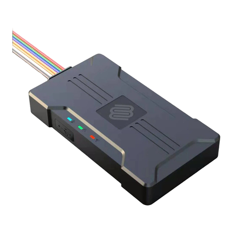
The Safe-Fly ADS-B compliant GPS module with serial data combiner provides GPS position data as a
stand-alone module to various approved ADS-B out devices, or may be wired to any GRT EFIS to
provide high integrity GPS position data, and provide more serial ports for all GRT EFIS display units
except the WS and HS models. Included with the unit are a GPS antenna suitable for interior
mounting, and mounting hardware.
Compatibility
The Safe-Fly GPS module is fully compatible with any GRT Mini, Sport SX, Horizon HX, Horizon
HXr, Sport EX, or Horizon EX EFIS, and compatible with the Sport and Horizon WS and HS models
as a GPS navigation source and for use with ADS-B in/out devices, but will not provide a serial
combiner function for these models. It can also operate stand-alone with the ADS-B out devices listed
in the “Approved Devices” section. The minimum software versions that support the module are:
EFIS Minimum
Software Version
All models of Mini EFIS 3.00
Sport EX/Horizon EX 1.06
Sport SX 13.00
HX 9.00
HXr 5.01
Sport or Horizon WS* Any
Sport or Horizon HS* Any
* These units are not compatible with the serial data combiner and GPS accuracy indicator functions
provided by the Safe-Fly GPS, nor can these units be used to configure the Safe-Fly GPS. The Safe-Fly
may be ordered pre-configured as needed at no charge, allowing it provide GPS data to your ADS-B
output device. In addition, a serial output from the Safe-Fly may be configured to provide NMEA0183
GPS data to these EFIS models.
Use with Non-Compatible GRT and other systems
The Safe-Fly GPS module can be used with non-compatible systems, and without any connection to an
EFIS, with the following limitations:
__________________________________________________________________________________
Safe-Fly 2020 GPS – Rev P GRT Avionics, Inc
5

Default settings will allow the Safe-Fly GPS to work with an Uavionix EchoUAT with no
settings change.
Default settings will not allow the Safe-Fly GPS to work with a Trig TT22. However, the
module can be ordered with its configuration set as desired at no additional cost.
The integrity and accuracy data will not be indicated on the EFIS display unit.
The serial combiner function cannot be used.
For these installations we do recommend using the NMEA0183 output to the EFIS, to provide the EFIS
with a high-quality navigation source.
GPS unction
The Safe-Fly GPS Module utilizes a RAIM GPS which provides all data required for ADS-B 2020
compliance for ADS-B out devices listed in the “Approved Devices” section. The GPS data can also
be used with any GRT EFIS to provide the EFIS with a high-integrity navigation source. The module
communicates with compatible ADS-B out devices via a serial port connection, independent of the
EFIS display unit.
Multiple GPS Configuration for your GRT E IS
The high-integrity nature of this GPS position means the GRT EFIS user should configure the Safe-Fly
GPS as one of the two possible GPS sources to the EFIS display unit, if at least one of the GPS inputs
is not assigned to a panel mount GPS.
For installations without an external panel-mount GPS, configure the Safe-Fly GPS as GPS1 (or
whichever GPS is commonly selected as the navigation source). For installations with one panel
mount GPS that is approach capable, the Safe-Fly GPS should be used in lieu of a non-RAIM external
GPS module.
Note that if your display unit includes an internal GPS, it is set as GPS1, GPS2, or NONE via the
“Internal GPS” setting on the “General Setup” set menu. The internal GPS is a non-RAIM GPS in all
EFIS display units equipped with an internal GPS.
GPS Status Display (This section is preliminary)
All GRT EFIS display units, with the exception of the Sport and Horizon HS/WS models, will show the
integrity and accuracy of the GPS in the upper left corner of the screen. It should not be inferred that
the “Approach” accuracy allows the GPS to be used for IFR approaches, however this indication is
provided to enhance the understanding of the performance of their GPS installation. If GPS-INTEG is
__________________________________________________________________________________
Safe-Fly 2020 GPS – Rev P GRT Avionics, Inc
6

commonly displayed, or GPS-E or GPS-A is not observed, check the integrity of the antenna
connection and location of the antenna.
No accuracy or integrity information is known about this GPS, or horizontal
accuracy limit > nm.
Valid position integrity and horizontal accuracy limit > 1.0 nm, and less than .0
nm, typical of IFR enroute requirements. *
Valid position integrity and horizontal accuracy limit > 0.3 nm and less than 1.0
nm, typical of IFR LNAV approach requirements. *
No Integrity – Insufficient data for validating data with RAIM integrity test.
(Flashes Yellow and Green)
* The GPS and EFIS are not FAA certified.
Serial Data Combiner/Expander unction
In addition to the GPS functions, the module includes a serial port combiner function. The module
includes serial ports (input and output). One of these is dedicated for communication with the EFIS
display unit. The other 3 serial ports can be configured to send GPS data directly to an ADS-B output
device, or used to expand the number of serial ports available to your display unit.
Recommended Usage of Serial Combiner/Expander Serial Ports
The design of the serial port combiner minimizes data latency (delays), however, connecting the
following devices is not recommended due to their potential sensitivity to the additional latency.
GRT Autopilot Servos
Data to 3rd party autopilots, such as Trutrak and Trio
AHRS, especially when the system includes a connection to an autopilot
__________________________________________________________________________________
Safe-Fly 2020 GPS – Rev P GRT Avionics, Inc
7
GPS
GPS-E
GPS-A
GPS-Integ

Devices that provide large amounts of data at high baud rates (38 00+), such as ADS-B receivers or
XM weather will function through the combiner, but could exceed the capacity of the combiner and
reduce the available data that could be passed through the other serial ports. For this reason, high data
rate devices must be wired directly to the display unit to avoid data loss.
Installation
Mounting holes are provided in the four corners of the case for #8 flat head screws. Two screws are
sufficient when located in opposite corners for most installations. The module can be mounted in any
orientation. Typically, the unit is mounted in the forward part of the airplane so its antenna can be
positioned on the glare shield, and so it is near the GRT EFIS display units. The module should not be
exposed to water, or in a location where it is likely to get wet, or where temperatures will exceed 150
deg F when in normal operation.
The Safe-Fly includes threaded holes for - 0 screws to allow mounting of the Uavionx EchoUAT.
This simplifies the installation and reduces the number of devices that must be mounted.
To further simplify the installation, the Horizon and Sport 10.1 EFIS allow the Safe-Fly GPS to be
mounted to the rear of the EFIS using 8-32 x ¾” screws. Caution: Do not exceed 1” long screws to
avoid damaging the EFIS internal PC board.
Wiring
The Safe-Fly GPS will operate with or without a connection to a GRT EFIS. In most cases it will be
wired to a GRT EFIS to supply the EFIS with GPS data, and allow the use of the 3 serial ports on the
module. (The serial data from these ports is combined into the one serial data stream to the EFIS,
along with the GPS data, and transmitted to the EFIS via the Serial Control Out pin.) Typical wiring is
illustrated at the end of this manual.
Power and Ground
Power – Power must be provided to at least one of the three power inputs on pins 23,2 ,25. +9-32VDc
is required at 0.2A maximum. These inputs are isolated, and multiple power inputs can be used for
redundancy.
round - One ground connection is recommended, to any of the provided ground pins.
__________________________________________________________________________________
Safe-Fly 2020 GPS – Rev P GRT Avionics, Inc
8

PS Backup Power – This connection is optional. It will draw about 30 uA from the aircraft battery,
which is much smaller than the self-discharge rate of an aircraft battery. The GPS will acquire its
position in less than 20 seconds when the GPS backup power connection is not used.
Serial Ports
When planning an installation, keep in mind that one serial output on the GPS module is required if the
GPS is to provide data to an ADS-B out device. This connection minimizes latency, and allows GPS
data to be sent to your ADS-B out device without dependence on a GRT EFIS that may be connected to
it.
Control Port In/Out - This serial port is dedicated to use with a GRT EFIS. This connection allows the
EFIS to change the configuration of the module’s serial ports, and send and receive data from them.
Serial Ports 1,2,3 – These serial ports can be configured to transmit GPS data to an ADS-B output
device. Ports 1 and 2 outputs are provided on two pins, and port 3 on three pins, so that “tee-ing” into
an output when it is shared with more than one device is not required.
Safe- ly/SPC Configuration
The module is shipped pre-configured in its default configuration. This configuration can be changed
when the module is connected to a compatible GRT EFIS.
Default Safe- ly Configuration
The Safe-Fly GPS is shipped, configured to transmit NN33 on serial out 1, and NMEA0183 GPS data
on serial out 2 and 3, plus RAIM integrity and accuracy data, as indicated in the following table:
Current Default Settings
Serial Port Default Pins
Serial Port 1 Out 800 baud, NMEA0183 19,20
Serial Port 2 Out 9600 baud, NMEA0183 + RAIM 3
Serial Port 3 Out 115200 baud, NMEA0183 + RAIM
+ RAIM
1,2
__________________________________________________________________________________
Safe-Fly 2020 GPS – Rev P GRT Avionics, Inc
9

Prior to October 2017 (not applicable after that ship date).
Serial Port Default Pins
Serial Port 1 Out 38 00 baud, Safe Fly NN33 19,20
Serial Port 2 Out 9600 baud, NMEA0183 + RAIM 3,
Serial Port 3 Out 800 baud, NMEA0183 + RAIM 1,2,15
The configuration of the module can be changed by connecting it to a compatible GRT EFIS. The
configuration data is stored in the GPS module, allowing it to operate stand-alone after it is configured.
Unless specified in the setup for a particular transponder or UAT setup, the above settings should be
used.
E IS Configuration Settings
When the Safe-Fly is wired to a GRT EFIS (other than a HS or WS display unit), one serial port on the
EFIS display unit must be configured for this module. Since the GPS includes a serial port combiner,
the EFIS will provide you with additional serial ports via the Safe-Fly GPS inputs. Using the “Set
Menu”, “ eneral Setup”, configure the serial port on the EFIS that is wired to the “Serial
Control Input/Output” as “Safe-Fly PS and SPC”, at 115,200 baud. After saving these settings,
the General Setup menu will show additional settings associated with this module. They appear just
after the serial port configuration settings.
Setting Description
SPC Serial Port 1,2,3 Rate Rate applies to input and output
SPC Serial Port 1,2,3 Input Functions available are the same as the EFIS.
SPC Serial Port 1,2,3 Output Functions available are the same as the EFIS, with the
addition of multiple ADS-B GPS output functions..
GRT Safe-Fly GPS To use this GPS as a navigation source to the EFIS, set
it to “GPS1”, or “GPS2”. If not used as a navigation
source to the EFIS, set it to “Not Assigned”. Note that
the EFIS supports 2 GPS inputs, and only one GPS
input can be assigned to GPS1 or GPS2, so it may be
necessary to change an internal GPS input to “Not
Assigned”, or a serial input configured for GPS1 or
GPS2 must be set to “Not Used”.
__________________________________________________________________________________
Safe-Fly 2020 GPS – Rev P GRT Avionics, Inc
10
Table of contents

