ADB Safegate RELIANCE Guidance Sign User manual

RELIANCE
Guidance Sign and Gate Sign
User Manual
UM-4007, Rev. 6.0, 2022/07/18

A.0 Disclaimer / Standard Warranty
CE certification
The equipment listed as CE certified means that the product complies with the essential requirements concerning safety and
hygiene. The European directives that have been taken into consideration in the design are available on written request to
ADB SAFEGATE.
ETL certification
The equipment listed as ETL certified means that the product complies with the essential requirements concerning safety and
FAA Airfield regulations. The FAA directives that have been taken into consideration in the design are available on written
request to ADB SAFEGATE.
All Products Guarantee
ADB SAFEGATE will correct by repair or replacement per the applicable guarantee above, at its option, equipment or parts
which fail because of mechanical, electrical or physical defects, provided that the goods have been properly handled and
stored prior to installation, properly installed and properly operated after installation, and provided further that Buyer gives
ADB SAFEGATE written notice of such defects after delivery of the goods to Buyer. Refer to the Safety section for more
information on Material Handling Precautions and Storage precautions that must be followed.
ADB SAFEGATE reserves the right to examine goods upon which a claim is made. Said goods must be presented in the same
condition as when the defect therein was discovered. ADB SAFEGATE furthers reserves the right to require the return of such
goods to establish any claim.
ADB SAFEGATE's obligation under this guarantee is limited to making repair or replacement within a reasonable time after
receipt of such written notice and does not include any other costs such as the cost of removal of defective part, installation
of repaired product, labor or consequential damages of any kind, the exclusive remedy being to require such new parts to be
furnished.
ADB SAFEGATE's liability under no circumstances will exceed the contract price of goods claimed to be defective. Any returns
under this guarantee are to be on a transportation charges prepaid basis. For products not manufactured by, but sold by
ADB SAFEGATE, warranty is limited to that extended by the original manufacturer. This is ADB SAFEGATE's sole guarantee and
warranty with respect to the goods; there are no express warranties or warranties of fitness for any particular purpose or any
implied warranties of fitness for any particular purpose or any implied warranties other than those made expressly herein. All
such warranties being expressly disclaimed.
Standard Products Guarantee
Products manufactured by ADB SAFEGATE are guaranteed against mechanical, electrical, and physical defects (excluding
lamps) which may occur during proper and normal use for a period of two years from the date of ex-works delivery, and are
guaranteed to be merchantable and fit for the ordinary purposes for which such products are made.
Note
See your sales order contract for a complete warranty description.
Replaced or repaired equipment under warranty falls into the warranty of the original delivery. No new warranty
period is started for these replaced or repaired products.
FAA Certified products manufactured by ADB SAFEGATE
ADB SAFEGATE L858 Airfield Guidance Signs are warranted against mechanical and physical defects in design or manufacture
for a period of 2 years from date of installation, per FAA AC 150/5345-44 (applicable edition).
ADB SAFEGATE LED products (with the exception of obstruction lighting) are warranted against electrical defects in design or
manufacture of the LED or LED specific circuitry for a period of 4 years from date of installation, per FAA EB67 (applicable
edition). These FAA certified constant current (series) powered LED products must be installed, interfaced and powered with
and through products certified under the FAA Airfield Lighting Equipment Program (ALECP) to be included in this 4 (four) year
warranty. This includes, but is not limited to, interface with products such as Base Cans, Isolation Transformers, Connectors,
Wiring, and Constant Current Regulators.
UM-4007, Rev. 6.0, 2022/07/18 iii
Copyright © ADB Safegate, All Rights Reserved

Note
See your sales order contract for a complete warranty description.
Replaced or repaired equipment under warranty falls into the warranty of the original delivery. No new warranty
period is started for these replaced or repaired products.
Liability
WARNING
Use of the equipment in ways other than described in the catalog leaflet and the manual may result in personal injury,
death, or property and equipment damage. Use this equipment only as described in the manual.
ADB SAFEGATE cannot be held responsible for injuries or damages resulting from non-standard, unintended uses of its
equipment. The equipment is designed and intended only for the purpose described in the manual. Uses not described in the
manual are considered unintended uses and may result in serious personal injury, death or property damage.
Unintended uses, includes the following actions:
•Making changes to equipment that have not been recommended or described in this manual or using parts that are not
genuine ADB SAFEGATE replacement parts or accessories.
•Failing to make sure that auxiliary equipment complies with approval agency requirements, local codes, and all applicable
safety standards if not in contradiction with the general rules.
•Using materials or auxiliary equipment that are inappropriate or incompatible with your ADB SAFEGATE equipment.
•Allowing unskilled personnel to perform any task on or with the equipment.
© ADB SAFEGATE BV
This manual or parts thereof may not be reproduced, stored in a retrieval system, or transmitted, in any form or by any means,
electronic, mechanical, photocopying, recording, nor otherwise, without ADB SAFEGATE BV's prior written consent.
This manual could contain technical inaccuracies or typographical errors. ADB SAFEGATE BV reserves the right to revise this
manual from time to time in the contents thereof without obligation of ADB SAFEGATE BV to notify any person of such
revision or change. Details and values given in this manual are average values and have been compiled with care. They are
not binding, however, and ADB SAFEGATE BV disclaims any liability for damages or detriments suffered as a result of reliance
on the information given herein or the use of products, processes or equipment to which this manual refers. No warranty is
made that the use of the information or of the products, processes or equipment to which this manual refers will not infringe
any third party's patents or rights. The information given does not release the buyer from making their own experiments and
tests.
RELIANCE
iv
Copyright © ADB Safegate, All Rights Reserved

TABLE OF CONTENTS
1.0 Safety ....................................................................................................................................................................................... 1
1.1 Safety Messages ........................................................................................................................................................................................................ 1
1.1.1 Introduction to Safety ................................................................................................................................................................................. 2
1.1.2 Intended Use .................................................................................................................................................................................................. 2
1.1.3 Material Handling Precautions: Storage .............................................................................................................................................. 3
1.1.4 Material Handling: Heavy Equipment .................................................................................................................................................. 3
1.1.5 Material Handling Precautions: Fasteners .......................................................................................................................................... 3
1.1.6 Operation Safety ........................................................................................................................................................................................... 4
1.1.7 Maintenance Safety ..................................................................................................................................................................................... 4
1.1.8 Material Handling Precautions, ESD ..................................................................................................................................................... 5
1.1.9 Arc Flash and Electric Shock Hazard ..................................................................................................................................................... 5
2.0 About this Manual ................................................................................................................................................................. 7
3.0 Introduction ............................................................................................................................................................................ 9
3.1 LED Signs for Airfield Guidance and Gate ....................................................................................................................................................... 9
3.2 Power and Monitoring Versions ....................................................................................................................................................................... 12
4.0 Installation ............................................................................................................................................................................ 13
4.1 Standard Hardware and Preparation .............................................................................................................................................................. 13
4.1.1 Tools to use .................................................................................................................................................................................................. 15
4.1.2 External electrical Connections ............................................................................................................................................................. 16
4.2 Mounting the Sign ................................................................................................................................................................................................. 17
4.3 Mounting a Tether Wire ....................................................................................................................................................................................... 21
4.3.1 Tether Wire - without pre-drilled Holes ............................................................................................................................................ 21
4.3.2 Tether Wire - with pre-drilled Holes ................................................................................................................................................... 23
4.4 Electrical Connection ............................................................................................................................................................................................. 24
4.5 Bird Deterrent Spikes SG19216 (optional) .................................................................................................................................................... 25
4.6 Reflective Tape ......................................................................................................................................................................................................... 26
4.7 Gate Sign ................................................................................................................................................................................................................... 26
5.0 Operation .............................................................................................................................................................................. 29
6.0 Maintenance ......................................................................................................................................................................... 31
6.1 Replace a Front Panel ............................................................................................................................................................................................ 32
6.2 Replace an LED strip .............................................................................................................................................................................................. 33
6.3 Replace an LED Adapter Card ............................................................................................................................................................................ 36
6.4 Replace a Converter (6.6A series circuit signs) ............................................................................................................................................ 38
6.5 Replace a Converter (VAC parallel circuit signs) ......................................................................................................................................... 40
6.6 Replace the Complete Electronics Box ........................................................................................................................................................... 41
6.7 Replace a Damaged Power Cable .................................................................................................................................................................... 48
6.8 Replace a Frangible Coupling ............................................................................................................................................................................ 50
6.9 Reset the Fail-open Converter ........................................................................................................................................................................... 51
6.10 Troubleshooting ................................................................................................................................................................................................... 52
6.10.1 The Sign does not light up correctly ............................................................................................................................................... 52
6.10.2 The Sign has mechanical Issues ......................................................................................................................................................... 52
6.10.3 Internal Wiring - 6.6A Series Powered LED ................................................................................................................................... 53
6.10.4 Internal Wiring - Voltage Powered LED Guidance ...................................................................................................................... 54
6.10.5 Internal Wiring - Voltage Powered LED Gate ............................................................................................................................... 55
7.0 Spare Parts ............................................................................................................................................................................ 57
7.1 RELIANCE Sign ......................................................................................................................................................................................................... 57
7.2 Ordering Codes ....................................................................................................................................................................................................... 63
8.0 SUPPORT ............................................................................................................................................................................... 65
8.1 ADB SAFEGATE Website ....................................................................................................................................................................................... 65
8.2 Recycling .................................................................................................................................................................................................................... 65
8.2.1 Local Authority Recycling ....................................................................................................................................................................... 65
UM-4007, Rev. 6.0, 2022/07/18 v
Copyright © ADB Safegate, All Rights Reserved


1.0 Safety
Introduction to Safety
This section contains general safety instructions for installing and using ADB SAFEGATE equipment. Some safety instructions
may not apply to the equipment in this manual. Task- and equipment-specific warnings are included in other sections of this
manual where appropriate.
1.1 Safety Messages
HAZARD Icons used in the manual
For all HAZARD symbols in use, see the Safety section. All symbols must comply with ISO and ANSI standards.
Carefully read and observe all safety instructions in this manual, which alert you to safety hazards and conditions that may
result in personal injury, death or property and equipment damage and are accompanied by the symbol shown below.
WARNING
Failure to observe a warning may result in personal injury, death or equipment damage.
DANGER - Risk of electrical shock or ARC FLASH
Disconnect equipment from line voltage. Failure to observe this warning may result in personal injury, death, or
equipment damage. ARC Flash may cause blindness, severe burns or death.
WARNING - Wear personal protective equipment
Failure to observe may result in serious injury.
WARNING - Do not touch
Failure to observe this warning may result in personal injury, death, or equipment damage.
CAUTION
Failure to observe a caution may result in equipment damage.
Qualified Personnel
Important Information
The term qualified personnel is defined here as individuals who thoroughly understand the equipment and its safe
operation, maintenance and repair. Qualified personnel are physically capable of performing the required tasks, familiar
with all relevant safety rules and regulations and have been trained to safely install, operate, maintain and repair the
equipment. It is the responsibility of the company operating this equipment to ensure that its personnel meet these
requirements.
Always use required personal protective equipment (PPE) and follow safe electrical work practice.
UM-4007, Rev. 6.0, 2022/07/18 1
Copyright © ADB Safegate, All Rights Reserved

1.1.1 Introduction to Safety
CAUTION
Unsafe Equipment Use
This equipment may contain electrostatic devices, hazardous voltages and sharp edges on components
• Read installation instructions in their entirety before starting installation.
• Become familiar with the general safety instructions in this section of the manual before installing,
operating, maintaining or repairing this equipment.
• Read and carefully follow the instructions throughout this manual for performing specific tasks and
working with specific equipment.
• Make this manual available to personnel installing, operating, maintaining or repairing this
equipment.
• Follow all applicable safety procedures required by your company, industry standards and
government or other regulatory agencies.
• Install all electrical connections to local code.
• Use only electrical wire of sufficient gauge and insulation to handle the rated current demand. All
wiring must meet local codes.
• Route electrical wiring along a protected path. Make sure they will not be damaged by moving
equipment.
• Protect components from damage, wear, and harsh environment conditions.
• Allow ample room for maintenance, panel accessibility, and cover removal.
• Protect equipment with safety devices as specified by applicable safety regulations
• If safety devices must be removed for installation, install them immediately after the work is
completed and check them for proper functioning prior to returning power to the circuit.
Failure to follow this instruction can result in serious injury or equipment damage
Additional Reference Materials
Important Information
•IEC - International Standards and Conformity Assessment for all electrical, electronic and related technologies.
•IEC 60364 - Electrical Installations in Buildings.
•FAA Advisory: AC 150/5340-26 (current edition), Maintenance of Airport Visual Aid Facilities.
•Maintenance personnel must refer to the maintenance procedure described in the ICAO Airport Services Manual,
Part 9.
•ANSI/NFPA 79, Electrical Standards for Metalworking Machine Tools.
•National and local electrical codes and standards.
1.1.2 Intended Use
CAUTION
Use this equipment as intended by the manufacturer
This equipment is designed to perform a specific function, do not use this equipment for other purposes
• Using this equipment in ways other than described in this manual may result in personal injury, death
or property and equipment damage. Use this equipment only as described in this manual.
Failure to follow this instruction can result in serious injury or equipment damage
RELIANCE
Safety
2
Copyright © ADB Safegate, All Rights Reserved

1.1.3 Material Handling Precautions: Storage
CAUTION
Improper Storage
Store this equipment properly
• If equipment is to be stored prior to installation, it must be protected from the weather and kept free
of condensation and dust.
Failure to follow this instruction can result in equipment damage
1.1.4 Material Handling: Heavy Equipment
DANGER
Unstable load
Use caution when moving heavy equipment
• Use extreme care when moving heavy equipment.
• Verify that the moving equipment is rated to handle the weight.
• When removing equipment from a shipping pallet, carefully balance and secure it using a safety
strap.
Failure to follow this instruction can result in death, serious injury, or equipment damage
1.1.5 Material Handling Precautions: Fasteners
DANGER
Foreign Object Damage - FOD
This equipment may contain fasteners that may come loose - torque properly.
• Only use fasteners of the same type as the one originally supplied with the equipment.
• Use of incorrect combination of gaskets, bolts and nuts can create severe damages to the product
installation and create safety risk .
• You need to know what base the light fixture will be installed in, in order to chose the correct gasket,
bolts and nuts.
• Bolt type, length, and torque value are determined by type of base, height of spacers used, and clamp
force required in FAA Engineering Brief No 83 (latest revision).
• Due to the risk of bolts vibrating loose, do not use any type of washer with the fixing bolts (such as
split lock washers) other than an anti-vibration washer. Anti-vibration washers as defined in FAA EB
83 (latest edition) must be used. For installations other than FAA, use the base can manufacturer's
recommendations.
• Always tighten the fasteners to the recommended torque. Use a calibrated torque wrench and apply
the recommended adhesive type.
• Obey the instructions of the adhesives necessary for the fasteners.
Failure to follow these warnings may cause the fasteners to loosen, damage the equipment,
potentially to loosen the equipment. This can lead to a highly dangerous situation of FOD, with
potential lethal consequences.
Note
To minimize the risk of errors, the ADB SAFEGATE Sales Representative will have information on which gasket goes
with which base. This information is also provided in the product Data sheets, the User Manuals and the Spare Part
Lists.
UM-4007, Rev. 6.0, 2022/07/18 3
Copyright © ADB Safegate, All Rights Reserved
CAUTION
Use of incorrect combination of gaskets, bolts and nuts can create severe damages to the product installation and
create multiple safety risks.
To obtain a safe and watertight installation the O-ring and retaining bolt stated in the document must be used.
You need to know what base the light fixture will be installed in, in order to choose the correct gasket, bolts and nuts.
Failure to follow these cautions can result in equipment damage or aircraft FOD.
1.1.6 Operation Safety
CAUTION
Improper Operation
Do Not Operate this equipment other than as specified by the manufacturer
• Only qualified personnel, physically capable of operating the equipment and with no impairments in
their judgment or reaction times, should operate this equipment.
• Read all system component manuals before operating this equipment. A thorough understanding of
system components and their operation will help you operate the system safely and efficiently.
• Before starting this equipment, check all safety interlocks, fire-detection systems, and protective
devices such as panels and covers. Make sure all devices are fully functional. Do not operate the
system if these devices are not working properly. Do not deactivate or bypass automatic safety
interlocks or locked-out electrical disconnects or pneumatic valves.
• Protect equipment with safety devices as specified by applicable safety regulations.
• If safety devices must be removed for installation, install them immediately after the work is
completed and check them for proper functioning.
• Route electrical wiring along a protected path. Make sure they will not be damaged by moving
equipment.
• Never operate equipment with a known malfunction.
• Do not attempt to operate or service electrical equipment if standing water is present.
• Use this equipment only in the environments for which it is rated. Do not operate this equipment
in humid, flammable, or explosive environments unless it has been rated for safe operation in these
environments.
• Never touch exposed electrical connections on equipment while the power is ON.
Failure to follow these instructions can result in equipment damage
1.1.7 Maintenance Safety
DANGER
Electric Shock Hazard
This equipment may contain electrostatic devices
• Do not operate a system that contains malfunctioning components. If a component malfunctions,
turn the system OFF immediately.
• Disconnect and lock out electrical power.
• Allow only qualified personnel to make repairs. Repair or replace the malfunctioning component
according to instructions provided in its manual.
Failure to follow these instructions can result in death or equipment damage
RELIANCE
Safety
4
Copyright © ADB Safegate, All Rights Reserved

1.1.8 Material Handling Precautions, ESD
CAUTION
Electrostatic Sensitive Devices
This equipment may contain electrostatic devices
• Protect from electrostatic discharge.
• Electronic modules and components should be touched only when this is unavoidable e.g. soldering,
replacement.
• Before touching any component of the cabinet you shall bring your body to the same potential as the
cabinet by touching a conductive earthed part of the cabinet.
• Electronic modules or components must not be brought in contact with highly insulating materials
such as plastic sheets, synthetic fiber clothing. They must be laid down on conductive surfaces.
• The tip of the soldering iron must be grounded.
• Electronic modules and components must be stored and transported in conductive packing.
Failure to follow this instruction can result in equipment damage
1.1.9 Arc Flash and Electric Shock Hazard
DANGER
Series Circuits have Hazardous Voltages
This equipment produces high voltages to maintain the specified current - Do NOT Disconnect while
energized.
• Allow only qualified personnel to perform maintenance, troubleshooting, and repair tasks.
• Only persons who are properly trained and familiar with ADB SAFEGATE equipment are permitted to
service this equipment.
• An open airfield current circuit is capable of generating >5000 Vac and may appear OFF to a meter.
• Never unplug a device from a constant current circuit while it is operating; Arc flash may result.
• Disconnect and lock out electrical power.
• Always use safety devices when working on this equipment.
• Follow the recommended maintenance procedures in the product manuals.
• Do not service or adjust any equipment unless another person trained in first aid and CPR is present.
• Connect all disconnected equipment ground cables and wires after servicing equipment. Ground all
conductive equipment.
• Use only approved ADB SAFEGATE replacement parts. Using unapproved parts or making
unapproved modifications to equipment may void agency approvals and create safety hazards.
• Check the interlock systems periodically to ensure their effectiveness.
• Do not attempt to service electrical equipment if standing water is present. Use caution when
servicing electrical equipment in a high-humidity environment.
• Use tools with insulated handles when working with airfield electrical equipment.
Failure to follow these instructions can result in death or equipment damage
UM-4007, Rev. 6.0, 2022/07/18 5
Copyright © ADB Safegate, All Rights Reserved

RELIANCE
Safety
6
Copyright © ADB Safegate, All Rights Reserved

2.0 About this Manual
This document includes RELIANCE™ airfield sign information with focus on safety, installation and maintenance procedures.
For more information, see www.adbsafegate.com.
Note
It is very important to read this document before any work is started.
UM-4007, Rev. 6.0, 2022/07/18 7
Copyright © ADB Safegate, All Rights Reserved

RELIANCE
About this Manual
8
Copyright © ADB Safegate, All Rights Reserved

3.0 Introduction
3.1 LED Signs for Airfield Guidance and Gate
Compliance with Standards
ICAO Annex 14 Volume I (current edition)
EASA CS-ADR-DSN (current edition)
Australia MOS 139
NATO STANAG 3316
STAC SPE/STAC/SE/E/VIS/6008
AENA DIN/DSEYN/PPT/022-02/12
ROS/MAK
CE
UKCA
Uses
Information Sign Informational Direction, Destination, and Boundary signs - black inscription on a yellow background. Designed
to guide pilots to a particular point on the airfield by identifying runway exits, taxiway directions, taxiway
intersections, taxiway ending, and inbound/outbound destinations, boundaries.
Mandatory Sign Mandatory Instruction sign – white inscription on a red background. Designed to identify holding positions,
runway intersections, and prohibit aircraft entry into designated areas.
Location Sign Runway and Taxiway Location signs - yellow inscription on a black background and only where it is a stand-alone
sign shall have a yellow border. Designed to identify taxiway and runway location on which the aircraft is located.
Aircraft Stand
Identification Sign
Gate and Stand Identification signs - black inscription on a yellow background. Designed to identify to the pilots
the particular gate/stand location.
RELIANCE™ illuminated airfield guidance signs are used as information, mandatory instruction, position and direction
indicators in accordance with ICAO Annex 14, Section 5.4 Signs. The signs are available with 322 km/h or 480 km/h wind
load compliant options.
RELIANCE™ illuminated gate signs are used as aircraft stand identification sign in accordance with ICAO Annex 14, Section 5.4
Signs.
Features and Benefits
LED Technology ensures a future proof airfield sign investment that removes the uncertainty of the proposed international
phase out regulations for the traditional incandescent lamps.
•Long lasting light source
•Low power consumption
•Environmentally friendly
UM-4007, Rev. 6.0, 2022/07/18 9
Copyright © ADB Safegate, All Rights Reserved
•Durable and vibration resistant
•Dramatically reduce maintenance costs and airport operation interruptions
Designed for Harsh Environments
Designed for harsh environments to dramatically extend component life and increase operational efficiency.
•Anodized aluminum housings
•Stainless-steel hardware and fixings
•Built-in surge and lightning protection
•Legend panel is made of UV-resistant polycarbonate to withstand jet blasts and other external forces
•LED strip and electronics box tested and certified for IP67 protection
Construction
•Sign housing/frame made from aluminum
•Mounting feet and poles made from aluminum
•Electronics box made from aluminum
•Legend panel front of UV-resistant polycarbonate
Operating Conditions
Operating Condition Symbol Specification
Operating temperature TA-40 °C to +70 °C
Storage temperature TSTG -60 °C to +80 °C
Humidity RH Up to 100%
Power Consumption
Power Factor (PF) typically >95%. Use the table to calculate CCR load and transformer sizing. For circuits or signs operating as
low as 6.3A, the VA consumption may increase up to 5%.
Sign Size (mm)
(Height x Length)
Electrical
Supply
VA
Load
700 × 1150 6.6 A 20
700 × 1300 6.6 A 23
700 × 1600 6.6 A 27
700 × 1800 6.6 A 30
700 × 2100 6.6 A 35
700 × 2500 6.6 A 40
700 × 2650 6.6 A 42
700 × 3000 6.6 A 47
900 × 1150 6.6 A 29
900 × 1300 6.6 A 33
900 × 1600 6.6 A 40
900 × 1800 6.6 A 42
900 × 2100 6.6 A 48
900 × 2500 6.6 A 47
RELIANCE
Introduction
10
Copyright © ADB Safegate, All Rights Reserved
Sign Size (mm)
(Height x Length)
Electrical
Supply
VA
Load
900 × 2650 6.6 A 50
900 × 3000 6.6 A 56
900 × 900 Gate 230 VAC 22
1200 × 1200 Gate 230 VAC 32
700 × 1300 Gate 230 VAC TBD
Electrical Supply
RELIANCE™ Airfield Signs are available in parallel and series versions according to power requirements. RELIANCE™ Gate Signs
are available in parallel only.
Power Requirements
Constant Current Regulator
(Series system)
2.8-6.6 A, 50/60 Hz
3-7 step CCR
Mains Power System
(Parallel system)
120-240 VAC, 50/60 Hz
Dimensions and Weight
Dimensions are the overall outer dimensions of the sign frame. The visible face of the sign legend panel is 100 mm less than
the height and width of the sign frame. When installed and mounted onto poles and Y-shaped feet, the total sign height
increases by approximately 100 mm.
Sign Size (mm)
(Height x Length)
Weight (kg)
(322 km/h)
Weight (kg)
(480 km/h)
700 x 1150 24.8 24.8
700 x 1300 26.5 26.5
700 x 1600 31.0 35.0
700 x 1800 33.7 37.7
700 x 2100 41.2 41.2
700 x 2500 46.0 50.0
700 x 2650 51.4 51.4
700 x 3000 60.0 60.0
900 x 1150 28.8 33.3
900 x 1300 31.0 35.5
900 x 1600 36.0 44.5
900 x 1800 39.7 48.2
900 x 2100 48.2 52.7
900 x 2500 53.9 62.4
900 x 2650 56.4 64.9
900 x 3000 61.9 66.4
900 x 900 Gate 21.0 N/A
1200 x 1200 Gate 32.5 N/A
700 x 1300 Gate 24.5 N/A
UM-4007, Rev. 6.0, 2022/07/18 11
Copyright © ADB Safegate, All Rights Reserved

Note
900 x 900 mm gate sign is used to display the gate/stand number only. 1200 x 1200 mm gate sign is used to display
the gate/stand number and coordinates.
3.2 Power and Monitoring Versions
•MON – LED sign with integrated fail open technology with CCR monitoring capability, adjustable intensity following the
CCR current.
•Non-MON – Non-monitoring version with adjustable intensity following the CCR current.
•VAC – 120-240VAC 50/60Hz, constant intensity.
RELIANCE
Introduction
12
Copyright © ADB Safegate, All Rights Reserved
4.0 Installation
This section describes the different steps for successful installation of the sign.
Site planning and preparation is required before installation, according to ICAO Annex 14. For example, there are
requirements for placement near runways, taxiways and intersections, and requirements for mounting on solid, flat, level
surfaces.
4.1 Standard Hardware and Preparation
Signs are delivered with mounting hardware including poles, frangible couplings, mounting profiles, clamps, and mounting
bases.
Poles and Frangible Couplings Measurement
The sign length determines the number of poles required and delivered for installation. When installed, the total sign height
mounted on poles increases by 100 mm.
The sign length and height dimensions in the table refers to the outer dimensions of the frame. The length and height of the
face are 100 mm less the values below.
Table 1: Wind load requirement ICAO 322 km/h (FAA Mode 2)
Sign size (mm) Number of poles Frangible coupling C-C distances (mm)
700 x 1150 2 FC 1.8 700
700 x 1300 2 FC 1.8 850
700 x 1600 2 FC 1.8 1150
700 x 1800 2 FC 2.2 1350
700 x 2100 3 FC 1.8 830
700 x 2500 3 FC 1.8 1030
700 x 2650 4 FC 1.6 730
700 x 3000 4 FC 1.8 850
900 x 1150 2 FC 2.6 700
900 x 1300 2 FC 2.6 850
900 x 1600 2 FC 2.6 1150
900 x 1800 2 FC 3.1 1350
900 x 2100 3 FC 2.2 830
900 x 2500 3 FC 2.6 1030
900 x 2650 3 FC 2.6 1100
900 x 3000 4 FC 2.6 850
Table 2: Wind load requirement ICAO 480 km/h (FAA Mode 3)
Sign size (mm) Number of poles Frangible coupling C-C distances (mm)
700 x 1150 2 FC 3.8 700
700 x 1300 2 FC 3.8 850
700 x 1600 3 FC 3.1 580
700 x 1800 3 FC 3.1 680
700 x 2100 3 FC 3.8 830
UM-4007, Rev. 6.0, 2022/07/18 13
Copyright © ADB Safegate, All Rights Reserved
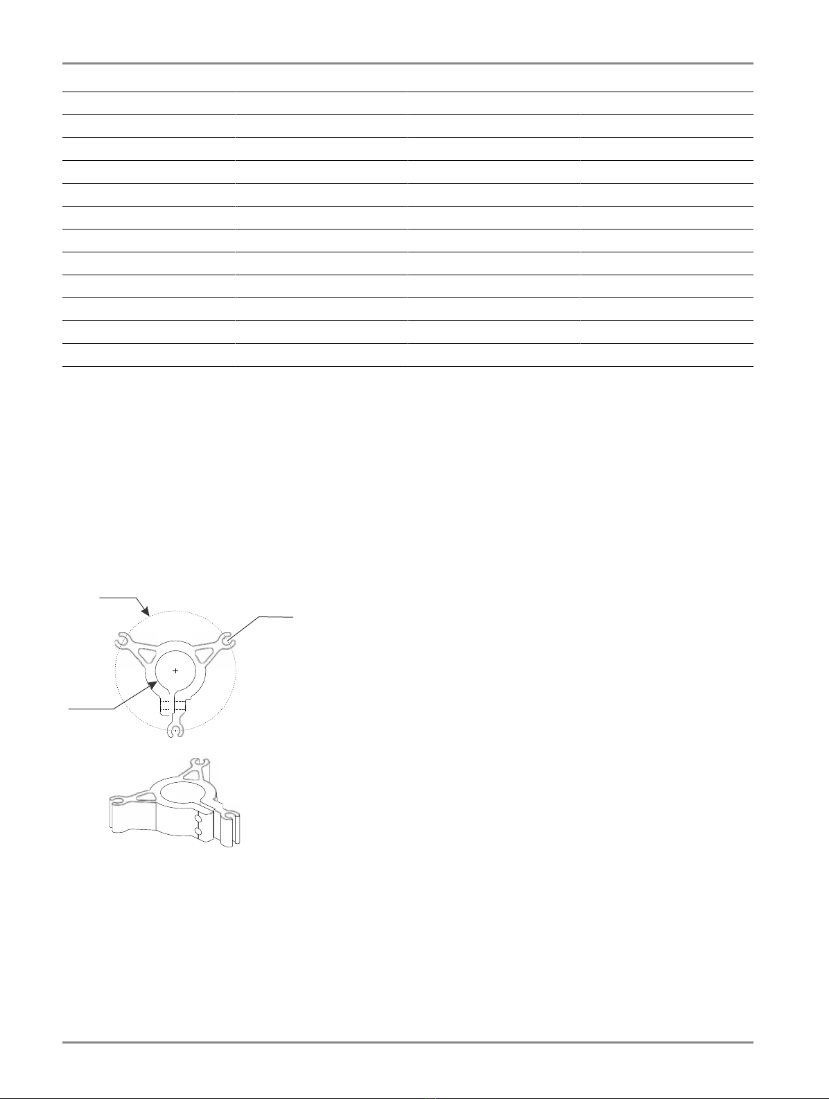
Table 2: Wind load requirement ICAO 480 km/h (FAA Mode 3) (Continued)
Sign size (mm) Number of poles Frangible coupling C-C distances (mm)
700 x 2500 4 FC 3.1 680
700 x 2650 4 FC 3.1 730
700 x 3000 4 FC 3.8 850
900 x 1150 3 FC 3.8 350
900 x 1300 3 FC 3.8 425
900 x 1600 4 FC 3.1 380
900 x 1800 4 FC 3.1 450
900 x 2100 4 FC 3.8 550
900 x 2500 5 FC 3.8 515
900 x 2650 5 FC 3.8 550
900 x 3000 5 FC 3.8 640
Mounting Information
The mounting distances between the poles are dependent on the sign length. The mounting bases and poles are mounted in
foundations, preferably concrete, installed on the surface of the sign location. The number of foundations required is equal to
the number of poles.
General recommendations, dimensions and appearance of mounting bases:
•Three M12 anchor bolts per base to fasten them to the foundation.
•The anchor bolts must be installed on a diameter of 180 mm with 120° spacing to mate with the base.
•Use the correct Center to Center (C-C) mounting distance, to layout anchoring points on the surface according to the sign
length and where the sign is to be installed. For information, see Table 1 and Table 2.
Ø180
R6.15
Ø60.3
7-inch
2.4-inch
Poles and Frangible Couplings Delivery
Poles with their respective frangible couplings are assembled at the factory. All poles are shipped in the same crate and
packaged in groups of 2, 3 or 4 poles, to help indicate which sign they are to be used with.
Frangible couplings are not universal, meaning there are different models intended to be used with different sign sizes. Check
the label in the lower left corner at the back of the sign to make sure that the sign is installed with the correct frangible
coupling. Make sure to verify the latest recommended frangible coupling, depending on RELIANCE Sign model, and apply
what is indicated in the spare parts. See RELIANCE Sign and www.adbsafegate.com.
RELIANCE
Installation
14
Copyright © ADB Safegate, All Rights Reserved
Other manuals for RELIANCE Guidance Sign
1
This manual suits for next models
1
Table of contents
Other ADB Safegate GPS manuals


