Gulf Coast Spas Coastal Air 5GR User manual

Coastal Air
(5GR)
5.8 KGS.
12.8 LBS.
Net weight
WARNING : Read and follow these instructions carefully and be mindful of all warnings shown throughout.

WARNING : TO REDUCE THE RISK OF FIRE, ELECTRICAL SHOCK, OR INJURY
TO PERSONS, PLEASE OBSERVE THE FOLLOWING :
READ AND SAVE THESE INSTRUCTIONS
1]. To ensure the success of the installation, be sure to read the instructions and review the diagrams
thoroughly before beginning.
2]. To avoid possible electric shock, be sure electricity is turned off at the main power box before wiring.
All electrical connections must be made in accordance with local codes, ordinances and/or the
National Electric Code. If you are unfamiliar with the methods of installing electrical wiring and
products, secure the services of a qualified and licensed electrician as well as someone who can
check the strength of the supportive ceiling members and make the proper installations and
connections.
3]. Make sure that your installation site will not allow rotating fan blades to come in contact with any
object. Blades should be at least 7 feet from floor when fan is in operation.
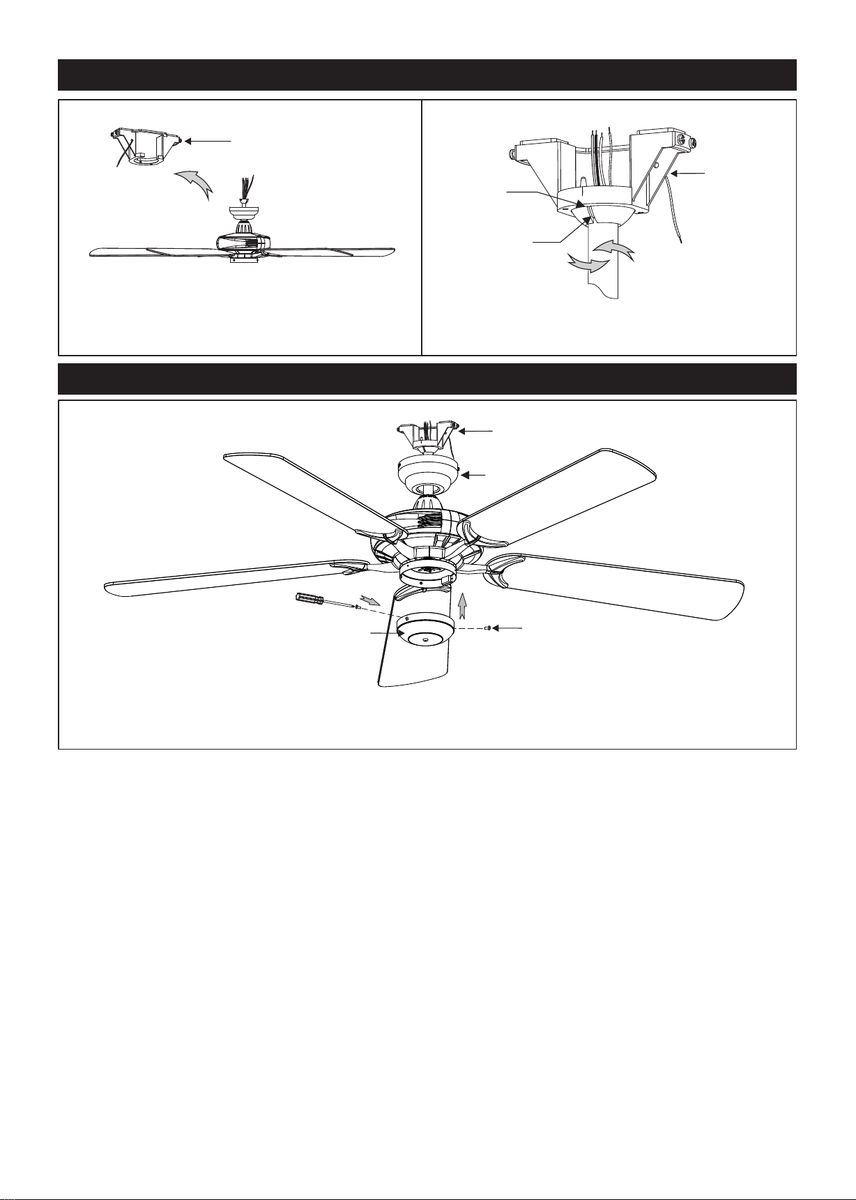
4]. If possible, mount ceiling fan on a ceiling joist - the joist must be able to support the motion and weight
of the moving fan. If the fan will be mounted on a ceiling outlet box, a 4" x 2-1/8" deep METAL octagon
box is required ; one UL listed as " suitable for fan support ". The box and its supporting members must
not be able to twist or work loose. DO NOT USE PLASTIC BOXES. Installation on a concrete ceiling should
be performed by qualified personnel.
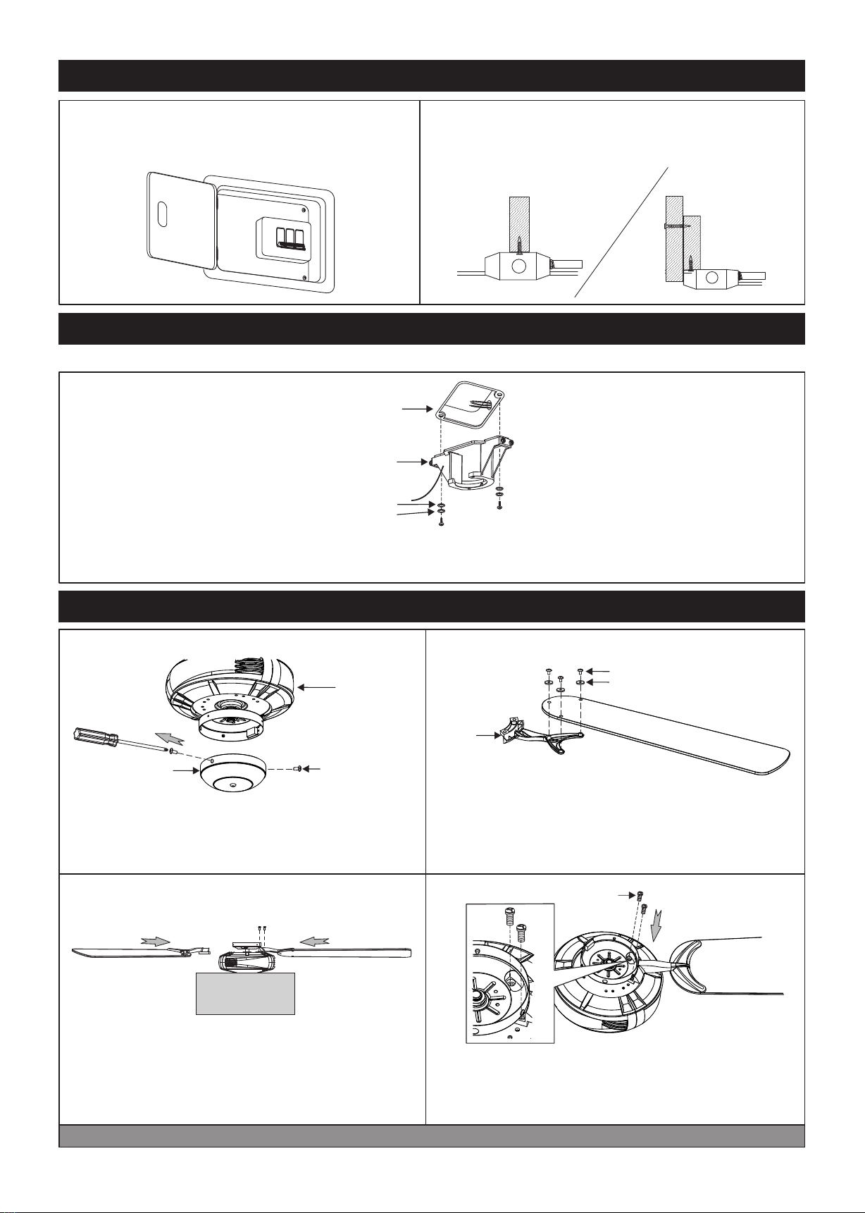
5]. Blades should be attached after motor housing is hung and in place. Fan motor housing should be
kept in carton until ready to be installed to protect its finish. If you are installing more than one ceiling
fan, make sure that you do not mix fan blade sets.
6]. After making electrical connections, spliced conductors should be turned upward and pushed
carefully up into outlet box. The wires should be spread apart with the grounded conductor and the
equipment - grounding conductor on one side of the outlet box and the " HOT " wires on the other side.
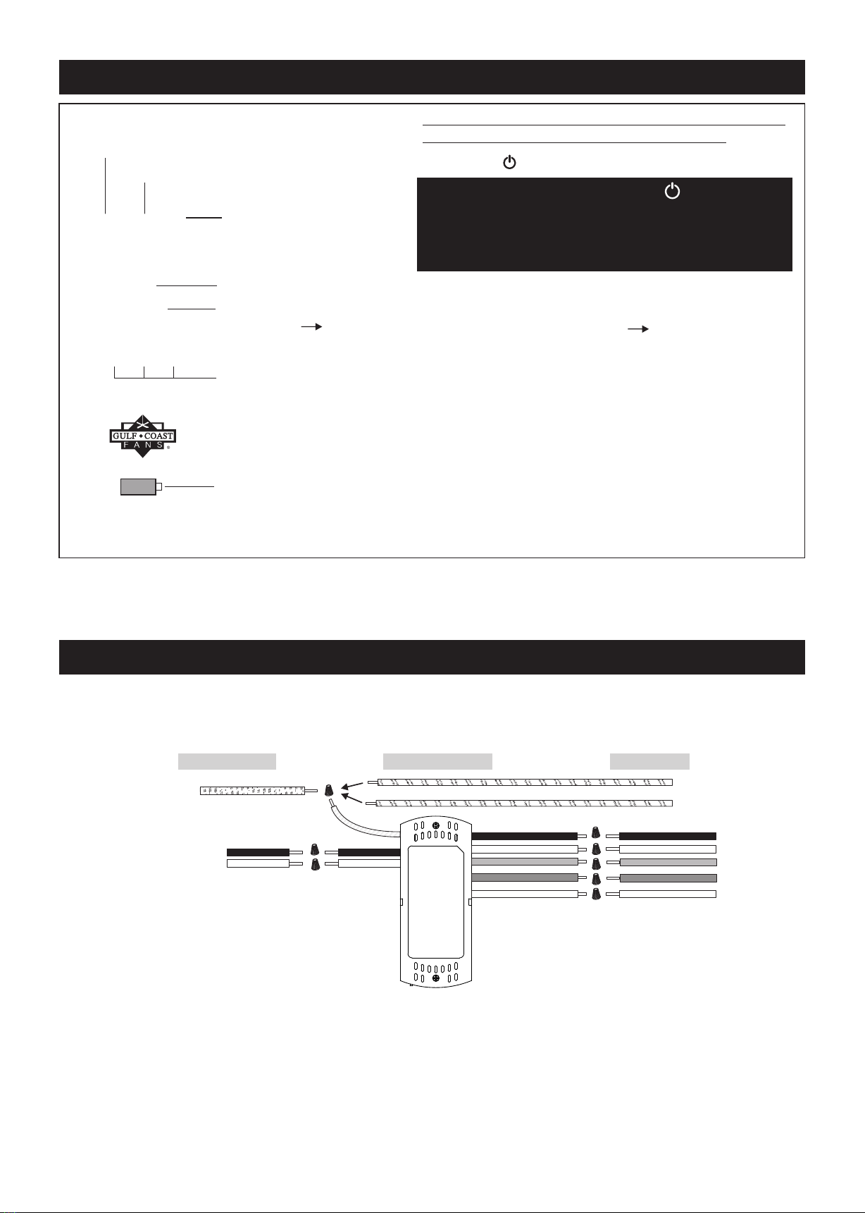
7]. Electrical diagrams are for reference only. Light kits that are not packed with the fan must be UL/ETL listed
and should be installed per the light kit's installation instructions.
8]. After fan is completely installed, check to make sure that all connections are secure to prevent fan
from falling and/or causing damage or injury.
9]. The fan can be made to work immediately after installation - the bearings are adequately charged
with grease. So that, under normal conditions, further lubrication should not be necessary.
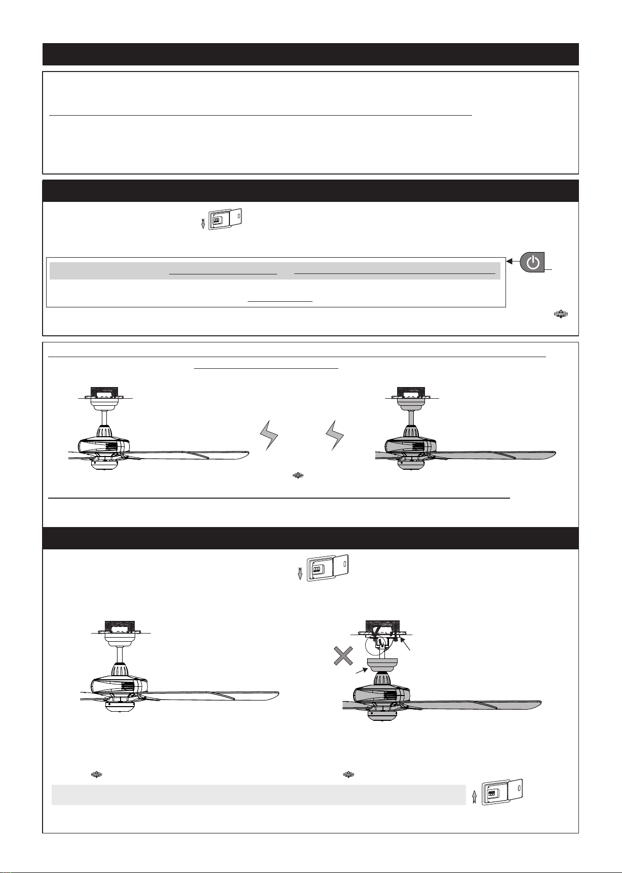
10]. The fan must be turned off and stopped before reversing fan direction.
11]. This fan is reversible.
12]. This fan is light kit adaptable.
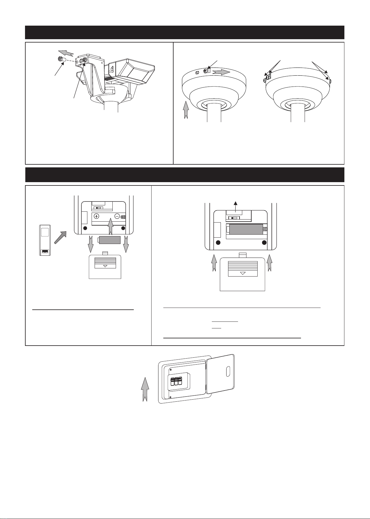
13]. This fan is controlled by remote.
14]. This fan is suitable for damp location use.
P1

Unpack and inspect fan carefully to be certain
all contents are included.
Blade Holder(5)
Blade(5)
Unit pack / all in one box
(Without Blade)
Fan Assembly
Canopy
For Wire Connection:
Wire Nut x 8
Hardware Bag
For Blade Balance :
Balanced slide x 1
Weight block (3G x 3)
3 GM
3 GM
3 GM
Wire
Downrod Assembly
Mounting Bracket
Hardware Bag
Wood Screw x 2
Wall plug anchor x 2
Remote Control (12V Battery Included)
For Blade Installation:
Rubber Washer x 11 (one spare washer included)
Blade Screw x 11 (one spare screw included)
Motor Screw x 16 (one spare screw included)
(Sold Separetely)
P2

1. HANGING SYSTEM INSTALLATION
OF FOFF OF F
Turn off power at breaker
box to avoid possible
electrical shock.
Use metal outlet box suitable
for fan support.
Outlet box must support 35 lbs min.
Note 1: Note 2:
WARNING: BLADES SHOULD BE AT LEAST 7 FEET FROM FLOOR
Installing mounting bracket to ceiling outlet box
1-1. Outlet Box
Mounting Bracket
Spring Washer
Flat Washer
1-1. Install mounting bracket to outlet box on ceiling by using screws included with the outlet box and
washers from the hardware bag.
2. BLADE INSTALLATION
*2-3. Use Styrofoam as cushion for this step.
*Place the fan assembly on Styrofoam with switch cap up.
*Note: Make sure all blade washers & screws are tightened to avoid operating noise.
Styrofoam
Blade Screw (3)
Blade
Holder
Rubber Washer (3)
Blade(5)
Blade(5)
Motor screw (2)
Fan Assembly
2-4.Secure Blade Assembly to the motor with 2 motor
screws provided from hardware bag.
NOTE: To prevent wobble, do not bend blade or
blade holder.
P3
2-2. Attach blade to blade holder with 3 blade screws
and 3 rubber washers provided from hardware bag.
Make sure all screws are firmly tightened.
(* Repeat until all 5 blades are installed firmly.)
2-1.Remove 3 screws from switch housing cover
and keep them for Step 5 in Page 5 .
Fan Assembly
Switch Cover
Screws(3)
Switch Housing
Cover

P4
3. DOWNROD INSTALLATION
Plastic Fastener
Yoke
Yoke Cover
3-2. Push the plastic fastener into slots of yoke.
3-3. Yoke Cover
Downrod
Assembly
Canopy
3-4. Insert the canopy onto downrod assembly.
3-1. Erect the lying downrod assembly up to
vertical position.
3-3. Thread the yoke cover to yoke until fully
tightened.

4-1. Lift fan assembly onto mounting bracket.
Mounting Bracket
4-2. Rotate fan so that the groove on the ball engages
the ridge in the mounting bracket.
4. HANGING THE FAN ONTO MOUNTING BRACKET
Mounting
Bracket
Ridge
Ball Groove
5. ATTACH THE SWITCH HOUSING BACK
Switch Cover Screws(3)
Switch Housing Cover
Attach the switch housing back and tighten 3 screws removed from Step 2-1 in Page 3.
P5
Mounting Bracket
Canopy

P6
6-3.Making electrical wire connection
The standard lead wire is 54" long.
You may need to cut all 5 lead wires (from motor) to proper length & strip them for wire connection
to make it easier for Canopy installation.
Follow diagram below and make sure that all exposed wires are secured inside wire nuts.
Note : Wires from house may vary in color. If the house wires do NOT include a ground wire (green)
AND the optional LED Light Kit is being installed, to prevent flickering, this unit must be
grounded/earthed to the home’s ground/earth; please consult an electrician.
After wiring is completed, gently push wires into junction box with wire nuts pointing upward.
From Remote
From House
(AC-N)
(AC-L)
White
Black
From Fan
Black
White
Black
White
Gray
Black
White
Gray
(For motor)
(For motor)
(For motor)
Green
( house ground wire )
Green
Green
( from Hanger Ball )
( from mounting bracket )
Blue Blue
(For Light Kit)
Orange Orange
(For Light Kit)
(For motor)
(For motor)
(For motor)
(For Light Kit)
(For Light Kit)
“ Special note: All Green grounding wires, from Hanger ball/Mounting bracket/Receiver,
must be well attached to House Ground/Ear th to prevent flickering of LED. ”
*Transmitter
*Receiver A Set B Set
FC912RS
P13Y808082
For 5GR
FC912RS
P13Y808082
1.REMOTE MODEL &
SERIAL NUMBER
2.FAN MODEL NUMBER
NOTICE:
Many remote sets for DC fans look the same. This remote set is pre-paired and labeled at the factory, please note the
following before operation:
1a. The Remote Model Number on transmitter and receiver must be the same.
1b. The Remote Serial Number will be the same on a pre-paired remote set. If it is different, it will need to be paired
(See page 9)
2. The Fan Model Number label must be the same as the fan’s model number in front page (5GR) for proper
operation.(There is no Fan Model Number on transmitter.)
3. Do not mix the remote sets if you are installing more than one fan.
3.Do not mix
6-2.Insert receiver into mounting bracket
NOTE: Do not squeeze all the wires while inserting the receiver into the mounting bracket.
6. WIRE CONNECTION
6-1. Verify that serial Number & Model Number match on the Receiver and Transmitter
Receiver
Mounting
Bracket

P7
7. CANOPY INSTALLATION
DIMMER< >ON
12V
DIMME R< >ON
8. REMOTE TRANSMITTER ASSEMBLY
DIMMER<>ON
8-1. Install the battery
Remove the back cover and install the
12V battery. (Included from remote box)
8-2. Check the dip switch position
(Original dip switch is on Dimming position)
Set dip switch in DIMMER position for LED dimming.
Set dip switch in ON position for LED ON/OFF only.
8-3. Re-install the back cover.
12V
Turn on power at breaker box, the fan is ready for operation!
(The receiver will have Beep sound)
OF F
OF F
OFF
ON
Back Cover
Back Cover
Note: Four screws are pre-screwed on mounting
bracket for canopy installation.
7-1. Remove left-hand side screw on mounting
bracket first and loosen the other one.
(Note: Please do the same for the other two
screws on the across side of mounting bracket.)
7-3.Screw (4)
(Tightening)
7-2.L Type Slots
7-1.Left-hand
side screw
(Removing)
Screw
(Loosening)
7-2. Push up the canopy and rotate the canopy slightly
until both two loosening screws are in the holes of L
type slots.
7-3. Tighten 4 screws firmly.

P8
9-1. ON/OFF - Fan
9-3. Reverse switch
9-2. Fan Speed
9-4. Timer (1hr/4hrs/8hrs)
9-5. Indicator
9-6. 12V battery (23AE/A23)
included, install in back
(1-Low Speed 5 -High Speed)
9. OPERATIONAL INSTRUCTION
9-1. Press button to turn the fan ON/OFF.
Warning: DO NOT PRESS THE BUTTON
FOR MORE THAN 4 SECONDS TO AVOID
FACTORY RESET AND THE LOSS OF
PRE-PAIRED PROGRAMING OF RECEIVER
AND TRANSMITTER!
Note: On every startup, the fan will move
forward & backward for 2~3 seconds.
9-2. Fan Speed: 1-Low Speed 5 -High Speed
9-3. Reverse switch
9-4. Timer (1hr/4hrs/8hrs)
9-5. Indicator
9-6. 12V battery (23AE/A23)
included, install in back
9-7. Light On/Off/Dimmer
Short press for Light ON/OFF
Hold the button for dimming the light
NOTE: Make sure the DIP switch is on
dimming position. (See 8-2 in Page 7)
All the button pressed will have a Beep sound
and the red indicator light will turn on.
Note: The remote retains the last settings (fan speed and light dimming level)
in memory. When turn on again, the fan will be on the same speed, and the light
will be at the same brightness.
9-7. Light function
TROUBLESHOOTING
In the event the fan does not operate properly, please perform the following steps.
9-8. Lower the canopy and check that all wires are connected properly.
9-9. Perform the remote Pairing Process at step 10-1 on P9.
From Remote
From House
(AC-N)
(AC-L)
White
Black
From Fan
Black
White
Black
White
Gray
Black
White
Gray
(For motor)
(For motor)
(For motor)
Green
( house ground wire )
Green
Green
( from Hanger Ball )
( from mounting bracket )
Blue Blue
(For Light Kit)
Orange Orange
(For Light Kit)
(For motor)
(For motor)
(For motor)
(For Light Kit)
(For Light Kit)

10.REMOTE PAIRING PROCESS
Make sure to turn off power at breaker box.
Disconnecting wire from #2 fan.
OFF OFF OFF
OFF
Turn on power at breaker box and #1 Fan is ready for pairing.
OFF
OFF
OFF
ON
Before starting the remote control setting process, lower the canopy of #2 Fan and disconnect the Black wire.
Put the wire nut on the black wire from the house.
#1 Fan is ready for setting.
A fan may need to have “Pairing Process” performed for the following issues.
1. Replacing the transmitter.
2. Replacing the receiver.
3. Multiple fans on the same circuit.
(In multiple fans situation, each fan must be wired up individually for the Pairing Process; see step 10-1.)
P9
1. Switch off the main power and make sure fan has completely stopped .
2. Install a New receiver or install the battery in a new transmitter before the Pairing Process.
3. Switch on the power again, and immediately:
This process must be done within 20 seconds after switching on the power.
This fan has completed the pairing successfully and the fan is ready for operation!
Press and hold the Fan On/Off button for 8 seconds until the Receiver “Long Beeps”.
OFFOFF OFF
OFF
10-2A. Pairing Process for Multiple fans (One transmitter for multiple receivers)
If you wish to use only one transmitter for two fans, simply wire up both fans at one time
and perform the Pairing Process at step 10-1 from a point between the two fans.
The Pairing Process is only necessary when there is an issue. Remote set is pre-paired from the factory and
should not require the Pairing Process.
10-2B. Pairing Process for Multiple fans (One transmitter for one receiver)
The Pairing Process must be performed on each remote set (transmitter and receiver) individually.
See the set up at step 10-3.
10-3. TO SET UP REMOTE FOR #1 FAN
(operating now)
*See the remote control setting process 10-1 to set up #1 Fan.
Outlet Box
#1 Fan
Outlet Box
#2 Fan
Outlet Box
#2 Fan
(Disconnecting)
Canopy
Mounting Bracket
Outlet Box
#1 Fan
10-1. PAIRING PROCESS FOR TRANSMITTER AND RECEIVER:

10-4. TO SET UP REMOTE FOR #2 FAN
Disconnecting wire from #1 Fan
Disconnect the Black wires from #1 Fans and connect the Black wires back to #2 Fan that you remove from 10-3.
Make sure to turn off power at breaker box.
OFFOFFOFF
OFF
#2 Fan is ready for setting
Turn on power at breaker box and #2 Fan is ready for setting.
OFF
OFF
OFF
ON
*See the remote control setting process for 10-1 to set up #2 Fan.
10-6. Switch on the main power and now each of these two fans are operated by its own
remote individually.
OFF
OFF
OFF
ON
10-5. RECONNECT ALL FANS
After all the fans have done the resetting process, reconnect all the wires for #1 fan & #2 fan,
and lift up the Canopy of #1 fan & #2 fan.
(operating now) (operating now)
NOTE: For more than two fans, the same rules apply. Make sure only one fan at a time is
connected to power when doing the Remote Setting. Already completed fans should be
disconnected until all fans have completed the Remote Setting process.
P10
Make sure to turn off power at breaker box.
OFFOFFOFF
OFF
Outlet Box
Mounting Bracket
#2 Fan
Outlet Box
#1 Fan
(Disconnecting)
Canopy
Mounting Bracket
#2 Fan
#1 Fan
Outlet Box
Mounting Bracket
#2 Fan
#2 Fan
Outlet Box
Mounting Bracket
#2 Fan
Outlet Box
#1 Fan
Outlet Box
#2 Fan
Table of contents
Popular Fan manuals by other brands

Space Pak
Space Pak WCSP-D series Installation, operation & maintenance manual

Ebmpapst
Ebmpapst R4E250-AH01-05 operating instructions

Ebmpapst
Ebmpapst A2D250-AI14-10 operating instructions

Delta
Delta breez GreenBuilder GBR80LED Installation and operating instructions

AAF
AAF AstroFan EC FFU Installation, operation and maintenance manual

Pro Breeze
Pro Breeze PB-01 instruction manual