hager TXE530 User manual

TXE530 1 6LE001714A
application software
KNX GPS Weather station
Electrical/Mechanical characteristics: see product user manual
Product reference Product designation Application software
ref
TP device
Radio device
TXE530 KNX GPS Weather station STXE530
1.x Version
A fair e

TXE530 2 6LE001714A
1. General ............................................................................................................................................................................. 3
1.1 About this guide........................................................................................................................................................... 3
1.2 About the program ETS............................................................................................................................................... 3
1.2.1 ETS compatibility .................................................................................................................................................. 3
1.2.2 Application descriptions ........................................................................................................................................ 3
1.3 Easy tool software appearance ................................................................................................................................... 3
2. General Description .......................................................................................................................................................... 4
2.1 Installation of the device .............................................................................................................................................. 4
2.1.1 Overview presentation .......................................................................................................................................... 4
2.1.2 Connection ............................................................................................................................................................ 5
2.1.3 Physical addressing .............................................................................................................................................. 5
2.1.4 Status of the station in the event of a power failure and re-start........................................................................... 6
2.2 Function modules of the application ............................................................................................................................ 7
3. Programming by ETS........................................................................................................................................................ 9
3.1 Parameters .................................................................................................................................................................. 9
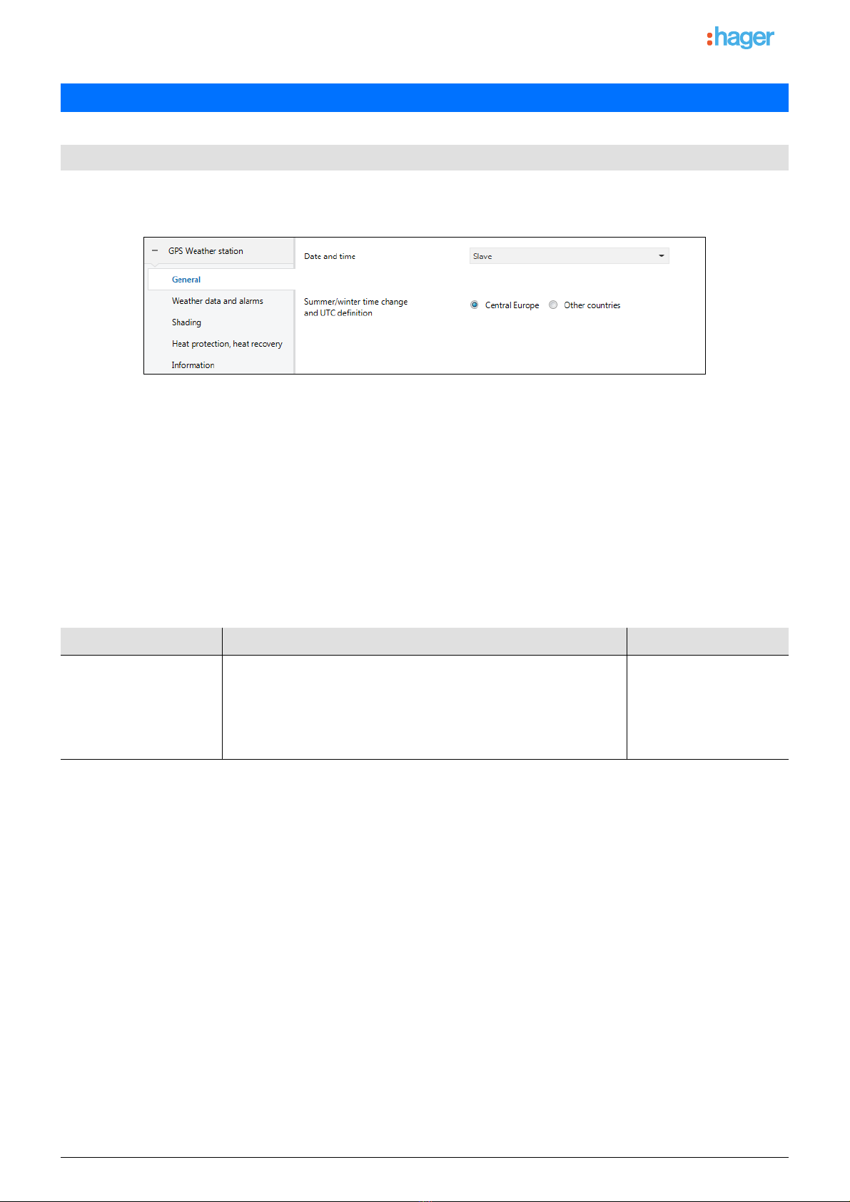
3.1.1 General ................................................................................................................................................................. 9
3.1.1.1 Date and time ................................................................................................................................................. 9
3.1.1.2 Time change................................................................................................................................................. 11
3.1.2 Weather data and alarms.................................................................................................................................... 13
3.1.2.1 Temperature measurement .......................................................................................................................... 14
3.1.2.2 Luminosity..................................................................................................................................................... 14
3.1.2.3 Wind speed................................................................................................................................................... 15
3.1.2.4 Rain alarm .................................................................................................................................................... 16
3.1.3 Shading ............................................................................................................................................................... 16
3.1.4 Heat protection, heat recovery ............................................................................................................................ 23
3.2 Communication objects ............................................................................................................................................. 26
3.2.1 Weather data and alarms ................................................................................................................................ 27
3.2.2 Overall parameters .......................................................................................................................................... 29
3.2.3 Shading............................................................................................................................................................ 34
3.2.4 Automatic control ............................................................................................................................................. 37
4. Programming by Easy Tool............................................................................................................................................. 39
4.1 Product overview ....................................................................................................................................................... 39
4.2 Date and time ............................................................................................................................................................ 40
4.3 Outdoor temperature - Frost alarm............................................................................................................................ 42
4.4 Luminosity - Day/night ............................................................................................................................................... 44
4.5 Wind speed - Wind alarm .......................................................................................................................................... 47
4.6 Rain alarm ................................................................................................................................................................. 49
4.7 Shading ..................................................................................................................................................................... 51
4.8 Heat protection/recovery ........................................................................................................................................... 60
5. Appendix ......................................................................................................................................................................... 64
5.1 Specifications ............................................................................................................................................................ 64
5.2 Characteristics........................................................................................................................................................... 64
5.3 Index of objects ......................................................................................................................................................... 65
Content

TXE530 3 6LE001714A
The purpose of this manual is to describe the operation and configuration of KNX devices using ETS software or Easy tool
software.
It consists of 4 parts:
- General information.
- The parameters and KNX objects available.
- The Easy tool configurations are available.
- Technical characteristics.
1.2.1 ETS compatibility
The application programs are compatible with ETS4 and ETS5. They can be downloaded from our website under the order
number.
1.2.2 Application descriptions
This product can also be configured using the TXA100 configuration tool. It is composed of a TJA665 configuration server. It is
essential to update the configuration server software version. (Please refer to the TXA100 user manual).
1. General
1.1 About this guide
1.2 About the program ETS
ETS Version File extension of compatible files
ETS4 (V4.1.8 or higher) *.knxprod
ETS5 *.knxprod
Application Product reference
STXE530 TXE530
1.3 Easy tool software appearance

TXE530 4 6LE001714A
2.1.1 Overview presentation
2. General Description
2.1 Installation of the device
Touchscreen Touchpad Smartphone
Local server
KNX shutter control
Thermostat KNX
Radio switch
KNX
TXE530
ETHERNET
Tasks
24 V =
Supply
24 V =
Shutter/blind output module

TXE530 5 6LE001714A
2.1.2 Connection
1 Spring terminal for power, for solid conductors up to 1.5 mm2or for stranded conductors
2 Location for the built-in rain sensor connector on the cover of the housing
3 GPS antenna
4 Terminal KNX +/-
5 Physical addressing button
6 Physical addressing LED
2.1.3 Physical addressing
In order to perform the physical addressing or to check whether or not the bus is connected, press the lighted push button (see
chapter 2.1.2 for the button location).
Light on = bus connected and ready for physical addressing.
Programming mode is activated, until the physical address is transferred from ETS. Pressing the button again, exits programming
mode.
1
2
3
4
5
6

TXE530 6 6LE001714A
2.1.4 Status of the station in the event of a power failure and re-start
-Status of the station in the event of a power failure in the bus or auxiliary: the device does not broadcast.
-Status of the station in the event of power restoration to the bus or auxiliary and after programming or restarting:
The device sends all of the actions, as well as the switching outputs and statuses, according to the timelines defined
below:
The date and time are emitted from the first GPS signal following power failure or downloading.
Tasks Time
Rain, wind and frost alarms 20 s
Luminosity
Wind speed measurement
Precipitation detection
Temperature recordings
25 s
Shading control
Heat protection and heat recovery
30 s

TXE530 7 6LE001714A
The KNX-GPS weather station measures the temperature, wind speed and luminosity. It detects precipitations and receives the
time and location data through the GPS signal. In addition, it calculates the exact position of the sun (azimuth and elevation)
using the site coordinates and time.
All of the weather data is sent to the bus at regular intervals. This data can be received and operated by other KNX products or a
supervision system that it able to define the thresholds and establish logical combinations from among several quantities to
ultimately control the outputs depending on the threshold values.
The weather station enables direct control of the switch outputs thanks to the pre-defined alarm levels: rain and frost alarm, and 3
wind alarm levels. It can also ensure the shading or heat recovery functions by tracking the position of shutters or the tilt of slats
for blinds.
The sensors, data operation electronics and bus coupler electronics are stored in the compact housing of the KNX-GPS station.
■Luminosity and sun position
The light intensity is measured using a luminosity sensor. At the same time, the KNX-GPS weather station calculates the position
of the sun (azimuth and elevation) using the time and location.
■Wind speed measurement
The wind speed electronic record provides quiet and reliable operation, even during hail, snow and minus temperatures.
Turbulence and upslope winds close to the weather station are also recorded. This information is transmitted periodically and can
be used as a wind alarm control.
■Precipitation detection
The surface of the sensor is heated so that only droplets and flakes are identified as precipitation, thereby disqualifying fog or
thaw. When the rain or snow stops, the sensor dries quickly and indicates the end of precipitation. This information is transmitted
periodically and can be used as a rain alarm control.
■Temperature recordings
The outdoor temperature is measured using a sensor. This information is transmitted periodically and can primarily be used as a
display or, for example, as a frost alarm control.
■Operation associated with domovea
The quantities measured (lux °C m/s) can be used by domovea to configure the levels and control the ON/OFF outputs when the
threshold is exceeded.
■Date and time - GPS function
The weather station receives the date and time via its built-in GPS receiver. This allows it to manage the switch to daylight saving
time between winter and summer.
■Rain, wind and frost alarms
This function issues an alarm according to the weather data gathered up to a predefined threshold.
There are 3 types of alarms:
- Rain alarm
-Frostalarm
- Wind alarm defined by 3 thresholds (Alarm 1 - 4 m/s, Alarm 2 - 8 m/s, Alarm 3 - 12 m/s)
■Shading control
This function manages up to 4 facades with several levels of shading depending on the angle of slat blinds or shutter closure.
2.2 Function modules of the application

TXE530 8 6LE001714A
■Heat protection and heat recovery
This function is involved in indoor temperature management, depending on the level of sunlight and the season. In summer, the
heat protection function positions the shutters or blinds to prevent the part from becoming too warm. In winter, the heat recovery
function opens the shutters or blinds to heat up the part using sunlight. For facade 1 only, the purpose of the weather station is to
receive the ambient temperature of facade 1 (using a master part) to more accurately manage heat protection and recovery.
Communication objects
Date slave
KNX GPS Weather
station
Time slave
Date and time slave
Date and time request
Shading facade x deactivation
Heat protection/recovery deactivation
Indoor temperature for facade 1
Sun protection facade x slat angle %
Luminosity
Wind alarm 1
Wind alarm 3
Outdoor temperature
Date master
Date and time request
Shading status facade x
Wind speed
Day/night
Wind alarm 2
Rain alarm
Frost alarm
Date and time master
Sun protection facade x position %
Heat protection/recovery status
Heat protection/recovery deactivation status

* Default value
TXE530 9 6LE001714A
3.1.1 General
3.1.1.1 Date and time
The GPS module built into the device is able to send the date and time to the bus. When the weather station is set without
restrictions, data is sent every 12 hours (fixed value) and during the time changes between summer and winter.
A single time must be managed for the different sub-systems. This time may come from different sources::
- domovea if connected to the internet
- weather station
-clock
If there are several time sources on the system, the priority is as follows:
- internet via the service module
-GPS
- local time source (clock ...)
Date and time for Master
In the first instance, the current date and time can be set via the ETS. The weather station works with this data until a valid GPS
signal is received for the first time.
3. Programming by ETS
3.1
Parameters
Parameter Description Value
Date and time The device uses the time data from another device on the bus. Slave*
The device receives the time data through GPS and sends it to the
KNX bus every 12 hours.
Master
The device receives the time data through the GPS and does not send
it to the KNX bus.
Autonomous
Communication objects: 12 - Date and time request - Input (1 Bit - 1.017 DPT_Trigger)
13 - Date master - Output (3 Byte - 11.001 DPT_Date)
14 - Time master - Output (3 Byte - 10.001 DPT_TimeOfDay)
15 - Date and time master - Output (8 Byte - 19.001 DPT_Date_Time)

TXE530 10 6LE001714A
Date and time for Slave
In slave mode, the weather station synchronizes itself to the date and time of the master system. However, it always operates
with its own date and time when calculating the azimuth and elevation.
When the weather station does not receive date and time information over 2 successive tries (fixed value), it sends a request via
the object (Date and time request). If there is no response, the weather station switches automatically to master mode. When the
master device re-sends the date and time, the weather station returns to slave mode.
Date and time in Autonomous mode
The weather station operates with its own date and time to calculate the azimuth and elevation. No item is sent to or read on the
KNX bus.
Communication objects: 9 - Date slave - Input (3 Byte - 11.001 DPT_Date)
10 - Time slave - Input (3 Byte - 10.001 DPT_TimeOfDay)
11 - Date and time slave - Input (8 Byte - 19.001 DPT_Date_Time)
13 - Date master - Output (3 Byte - 11.001 DPT_Date)
14 - Time master - Output (3 Byte - 10.001 DPT_TimeOfDay)
15 - Date and time master - Output (8 Byte - 19.001 DPT_Date_Time)
16 - Date and time request - Output (1 Bit - 1.017 DPT_Trigger)

* Default value
TXE530 11 6LE001714A
3.1.1.2 Time change
The switch-over for daylight saving time (summer/winter and winter/summer) is carried out automatically or using specific
settings.
Parameter Description Value
Summer/winter time
change and UTC definition
The time change is carried out automatically according to the Central
Europe criteria.
Central Europe*
The time change is carried out through specific settings according to
the criteria in place in the country of installation. There are additional
settings that allow configuration for other countries.
Other countries

* Default value
TXE530 12 6LE001714A
Switch-over for daylight saving time
Example: If the time change takes place on the last Sunday of March at 2 am, select:
- First winter to summer time change Sunday after 24/03 at 2h 00m.
Summer/winter time change
Parameter Description Value
The First winter to summer
time change
This setting determines the day of the week on which
the time change will take place.
Sunday*
Monday
Tuesday
Wednesday
Thursday
Friday
Saturday
Any day
Parameter Description Value
After This setting determines at what time (day, month, hour,
minute) the change will take place.
Day 1...25*...31 day
Month 1...3*...12 month
Hours 0...2*...23 hours
Minutes 0*...59 minutes
Parameter Description Value
Summer time offset in
minutes
This setting determines the offset value in minutes
when the time changes (summer/winter; winter/
summer).
60* minutes: 0 to 60 min
Parameter Description Value
First summer/winter time
change
This setting determines the day of the week on which
the time change will take place.
Sunday*
Monday
Tuesday
Wednesday
Thursday
Friday
Saturday
Any day

* Default value
TXE530 13 6LE001714A
Example: If the time change takes place on the last Sunday of October at 3 am, select:
- First winter to summer time change Sunday after 24/10 at 3h 00m.
3.1.2 Weather data and alarms
Note: All of the settings in this tab are set and cannot be modified.
Parameter Description Value
After This setting determines at what time (day, month, hour,
minute) the change will take place.
Day 1...25*...31 day
Month 1...3*...12 month
Hours 0...2*...23 hours
Minutes 0*...59 minutes
Parameter Description Value
UTC offset in minutes This setting determines the value of the time difference
(in minutes) in relation to Greenwich Mean Time.
60* minutes: -720 to +780 min

TXE530 14 6LE001714A
3.1.2.1 Temperature measurement
The outdoor temperature is mainly used for the heating, ventilation and air conditioning systems. It can also be used as a display
on touch screens.
The frost alarm operates as follows:
- The frost alarm is activated (bit = 1) if the value measured is less than the threshold value (3 °C) for 5 minutes. It will
immediately be transmitted and every 10 minutes thereafter.
- The frost alarm is deactivated (bit = 0) is the value measured becomes greater than 5° C. It will immediately be transmitted
and every 10 minutes thereafter.
3.1.2.2 Luminosity
The outdoor luminosity is mainly used for lighting control systems and shading management, taking the position of the sun into
account. It can also be used as a display on touch screens.
The day/night information operates as follows:
- The "Day" information is activated (bit = 0) if the value measured is greater than the threshold value + hysteresis (12 Lux)
for more than one minute (fixed value).
- The "Night" information is activated (bit = 1) if the value measured is less than the threshold value (10 Lux) for one minute.
Parameter Description Value
Outdoor temperature The temperature value is periodically sent every 30
minutes and at each change in temperature if it is
greater than +/- 0.5° C from the last measurement.
Emission of value every 30 minutes
Emission on change: +/- 0.5 °C
Frost alarm The frost alarm (1 bit) can be used directly by the ON/
OFF output modules.
The alarm threshold is set at 3 °C and the alarm will be
transmitted every 10 minutes.
3 °C fixed value, emission every 10
minutes
Communication objects: 0 - Outdoor temperature - Output (2 Byte - 9.001 DPT_Value_Temp)
8 - Frost alarm - Output (1 Bit - 1.005 DPT_Alarm)
Parameter Description Value
Luminosity The luminosity value is periodically sent every 30
minutes and at each change if the variation is greater
than 20 % compared to the last measurement.
Emission of value every 30 minutes
Emission on change: +/- 20 %
Day/night The day/night information (1 bit) can be used directly by
the ON/OFF output modules.
The threshold is fixed at 10 Lux (fixed value), with a
hysteresis of 2 Lux (fixed value).
The information is sent each time the threshold is
exceeded (switching from day to night and night to day).
Emission day if value > 12 lux during 1
minute
Emission night if value < 10 lux during 1
minute
Communication objects: 2 - Luminosity - Output (2 Byte - 9.004 DPT_Value_Lux)
3 - Day/night - Output (1 Bit - 1.011 DPT_State)

TXE530 15 6LE001714A
3.1.2.3 Wind speed
The wind speed value is mainly used to secure shutters and blinds. It can also be used as a display on touch screens.
A communication object is available for each of the three alarms.
The wind alarm (1 to 3) operates as follows:
- The wind alarm is activated (bit = 1) if the value measured is greater than the threshold value for more than 2 seconds. It
will immediately be transmitted and every 10 minutes thereafter.
- The wind alarm is deactivated (bit = 0) if the value measured is less than the threshold value for more than 5 minutes. It
will immediately be transmitted and every 10 minutes thereafter.
Parameter Description Value
Wind speed The wind speed value is periodically sent every 30
minutes and at each change if the variation is greater
than 20 % compared to the last measurement.
Emission of value every 30 minutes
Emission on change: +/- 20 %
Wind alarm 1 wind alarm 1 (1 bit) can be used directly by the shutter/
blind output modules.
The alarm threshold is set at 4 m/s (14.4 km/h) and the
alarm will be transmitted every 10 minutes.
Emission every 10 minutes if wind speed
> 4 m/s
Wind alarm 2 wind alarm 2 (1 bit) can be used directly by the shutter/
blind output modules.
The alarm threshold is set at 8 m/s (28.8 km/h) and the
alarm will be transmitted every 10 minutes.
Emission every 10 minutes if wind speed
> 8 m/s
Wind alarm 3 wind alarm 3 (1 bit) can be used directly by the shutter/
blind output modules.
The alarm threshold is set at 12 m/s (43.2 km/h) and the
alarm will be transmitted every 10 minutes.
Emission every 10 minutes if wind speed
> 12 m/s
Communication objects: 1 - Wind speed - Output (2 Byte - 9.005 DPT_Value_Wsp)
4 - Wind alarm 1 - Output (1 Bit - 1.005 DPT_Alarm)
5 - Wind alarm 2 - Output (1 Bit - 1.005 DPT_Alarm)
6 - Wind alarm 3 - Output (1 Bit - 1.005 DPT_Alarm)

TXE530 16 6LE001714A
3.1.2.4 Rain alarm
The rain alarm mainly controls the opening and closing of canopies or skylights. It can also be used as a display on touch
screens.
The rain alarm operates as follows:
- The rain alarm is activated (bit = 1) when rain is detected. It will immediately be transmitted and every 10 minutes
thereafter.
- The rain alarm is deactivated (bit = 0) after a period of 5 minutes after rain has stopped. It will immediately be transmitted
and every 10 minutes thereafter.
3.1.3 Shading
The aim of the shading function is to provide further comfort for people in the room by preventing glare from the sun. To simplify
the use and configuration of the weather station, we recommend working with facades that are fitted only with shutters or only
with blinds.
The shading control options (blind or louver position and slat tilt positions) are associated with facades.
Facade controls
Parameter Description Value
Rain alarm The rain alarm (1 bit) can be used directly by the
shutter/blind output modules.
Emission every 10 minutes
Communication objects: 7 - Rain alarm - Output (1 Bit - 1.005 DPT_Alarm)
The majority of buildings have 4 facades. Creating a separate command for the sun
protection of each facade is recommended.
For U shaped buildings, only 4 facades must be controlled separately, insofar as several
are facing the same direction.
To manage shading on a facade with both blinds and shutters, two facades must be
registered: one for blinds and one for shutters. Here, facade 2 is for shutters and facade 4
is for blinds.
1
42
3
1
42
3
33
24
31
4
22
13

TXE530 17 6LE001714A
Facade direction
The direction of each facade must be defined in the setup for the shading function to operate correctly.
- Defining the direction of each facade used.
Example 1:
Example 2:
Direction:
Facade 1: N = 0°
Facade 2: E = 90°
Facade 3: S = 180°
Facade 4: W = 270°
Direction:
Facade 1: NE = 45°
Facade 2: SE = 135°
Facade 3: SW = 225°
Facade 4: NW = 315°
1
4
2
3
3
4
2
1

* Default value
TXE530 18 6LE001714A
Note: To manage a glazed roof or partially glazed roof, the roof must be declared as one of the facades with the setting (All =
360°).
Note: This is intended only for blinds with horizontal slats.
Parameter Description Value
Facade x The facade is not used for position tracking. Not active*
The facade is used for position tracking the rolling
shutters only.
Position tracking for shutters
The facade is used for position tracking the blinds
(position and tilt).
Position and slat tracking for blinds
Facade orientation in ° This setting defines the direction of the facade
according to the compass points.
N = 0°
NE = 45°
E = 90°
SE = 135°
S = 180°
SW = 225°
W = 270°
NW = 315°
All = 360°

TXE530 19 6LE001714A
Shading concept for rolling shutters and slat blinds:
With shading tracking, the sun protection is not fully lowered, thus allowing the sun to penetrate the room. In this way, users at the
bottom of the window can see out and plants on the windowsill will receive sunshine.
Note: Shading tracking can only be used when the sun protection is lowered from top to bottom (such as shutters, textile sun
protection or blinds with horizontal slats). This function is not usable for a sun protection that is pulled from one side to the other
or pulled in front of a window from both sides.
Shading with roller shutters
Shading is automatically controlled if the shading conditions on the relevant facade are fulfilled: luminosity threshold > 40 klux
and sun on the facade. The shading thus moves in line with the path of the sun. It starts with a minimum shutter closing value of
20 % and a maximum configurable closure between 20 and 80 %. Full automatic closure can only be obtained if the heat
protection function is activated.
Example of 80% maximum closure (default value):
Example Shutter position Sun position - Angle between
20% 46° ... 90°
40% 31° ... 45°
60% 16° ... 30°
80% 0° ... 15°
40 %
20 %
60 %
80 %
1 2 3 4
α
1
2
3
4

TXE530 20 6LE001714A
Example with maximum closure set at 40%:
Sun protection operation for shutters:
If the luminosity level is sufficient (more than 40 Klux for more than one minute) and the sun is shining on the facade:
- The shutter is positioned in line with the path of the sun between 20 % closure and the maximum shading position defined
by the configuration (20 to 80 %).
If the luminosity level is insufficient (less than 32 Klux for more than 15 minutes) or the sun is not shining on the facade:
- The shutter is positioned at a fixed value of 0 %.
Example Shutter position Sun position - Angle between
10% 46° ... 90°
20% 31° ... 45°
30% 16° ... 30°
40% 0° ... 15°
20 %
10 %
30 %
40 %
1 2 3 4
α
1
2
3
4
Other manuals for TXE530
1
Table of contents
Other hager Weather Station manuals
Popular Weather Station manuals by other brands

BEARWARE
BEARWARE 303530 manual

La Crosse Technology
La Crosse Technology 308-1414MBv2 Instructional manual

TFA
TFA 60.2545 instruction manual

Oregon Scientific
Oregon Scientific ECLIPSE user manual

IROX
IROX EBR808C instruction manual

Spectrum Technologies
Spectrum Technologies WatchDog 2000 Series product manual