Haier HLC15B-A User manual

HLC15B-A

1. Features
2. Safety Precautions
3. Images of Module and Circuit Boards
4. Key IC Description& Trouble Shooting Guide
5.Signal Flowing Chart
6. Bus Control Adjustment
7. Circuit Diagram

Features
NO.
Functions
Model
HLC15B-A
1 TFT BOE
2 Screen size 15inch
3 Aspect ratio 4:3
4 Resolution 1024×768
5 Brightness 250cd/m
2
6 Contrast(Darkroom) 500:1
7 Response time(ms) 8
8 Color system ATSC/NTSC
9 NO. of preset channels 181
10 Picture mode Yes
11 Angel of view H:120
°
/ V:100
°
12 Color display 16,777,216
13 Color level 16
14 OSDlanguages ENGLISH\FRENCH\SPANISH
15 AV stereo Yes
16 Surrounding sound No
17 Audio system M
18 Bass Yes
19 Balance Yes
20 Sound mode Yes
21 Mute Yes
22 BTSC Yes
23 AV input Yes
24 AV output No
25 Y CB CR Yes
26 Y PB PR Yes
27 S-video jack Yes
28 TV in Yes

Model
NO.
Functions
HLC15B-A
29 D-SUB jack Yes
30 DVI socket No
31 SCART socket No
32 Ear-Phone Out Yes
33 CCD,V-CHIP Yes
34 Semitransparent menu Yes
35 ZOOM No
36 16:9 mode No
37 Child Lock Yes
38 Quick View Yes
39 NO. of built-in speakers 2
40 Audio output power(Built-in)(W) 2*1.5
41 Total power input(W)80
42 Voltage range(V)120
43 Power frequency(Hz)60
44 Time of sleep timer(MINS) 120
45 Approval UL
46 Suitable market U.S.A

Safety Precautions
Warning
High voltages are used in the operation of this product.
Do not romove the cabinet back from your set. Refer
servicing to qualified service personnel.
Warning
To prevent fire or electrical shock hazard, Do not expose
the main unit to rain or moisture.
Warning
Do not drop or push objects into the television cabinet
slots or openings. Never spill any kind of liquid on the
television receiver.
Caution
If the television is to be built into a
compartment or similarly enclosed, the
minimum distances must be maintained.
Heat build-up can reduce the service life of
your television, and can also be dangerous.
!
Minimum
10c
20c
10c 5cm

Caution
Never stand on, lean on, push suddenly the product or its
stand. You should pay special attention to children to children.
Caution
Do not place the main unit on an unstable cart stand, shelf or
table. Serious injury to an individual, and damage to the
television, may result if it should fall.
Caution
When the product is not used for an extended period of time, it
is advisable to disconnect the AC power cord from the AC
outlet.
Caution
Avoid exposing the main unit to direct sunlight and other
source of the heat. Do not stand the television receiver
directly on other produces which give off heat. E. g. video
cassette players,Audio amplifiers. Do not block the
ventilation holes in the back cover. Ventilation is essential to
prevent failure of electrical component. Do not squash power
supply cord under the main unit.
Caution
The LCD panel used in this product is made of glass.
Therefore, it can break when the product is dropped or
applied with impact. Be careful not to be injured by
broken glass pieces in case the LCD panel breaks.
!
!
!
!
!

Images
of
Module
and Circuit Boards
1.images of Remote Board Subassembly
2.images of Control Panel Subassembly
3.images of Main Board
4.images of Power Supply

10/10/06 CONFIDENTIAL INFORMATION-DO NOT COPY 2
October 10, 2006 11:23 am
SupraHD-760-DTS-GEN-v1.0-Preliminary Release
Chapter 1. SupraHD-760 Overview
1.1 SupraHD Family
The ZR396xx family consists of:
• SupraHD-680 IC (ZR39680) - Digital TVs for the ATSC/DVB/OpenCable Market
• SupraHD-660 IC (ZR39660) - Digital TVs for the ATSC Market
• SupraHD-640 IC (ZR39640) - Digital ATSC upgrade for Analog TVs
The ZR397xx family consists of:
• SupraHD-760 IC (ZR39760) - Digital Flat Panel TVs for the ATSC Market
• SupraHD-740 IC (ZR39740) - Digital ATSC upgrade for Analog TVs
1.2 SupraHD-760 IC Description
The SupraHD-760 IC is a members of the SupraHD family of DTV controllers developed by Zoran. These
devices are intended to be used in ATSC-compliant television implementations. These devices include all of
the functionality required to support the television implementations shown in the following system block
diagrams.

SupraHD-760-DTS-GEN-v1.0-Preliminary Release
3 CONFIDENTIAL INFORMATION-DO NOT COPY 10/10/06
October 10, 2006 11:23 am
Figure 2 shows a typical system implementation using the SupraHD-760. This system can be designed and
manufactured in a very low-cost manner.
Figure 2: SupraHD-760 DTV System Diagram - FTA Implementation
Front
Panel
Rear Chassis
Connections
ZR39760
ATSC/
NTSC
Tuner
Analog
Mux
CVBS
IF IF
CVBS/S-Video In
I2C0
HI2C
HCEC
HDMI
MIF
Stereo
D/A
Virtual
Suround
ACLK
LRCLK
ADATAO0
ADATAO1
ADATAO2
As appropriate
for the design
CVBS
C
Y
Audio
A/D I2S0
L
CLKIN
IEC958
Audio
Amp
IRR
UART0
R
GPIOx
GPIOx
L Audio
R Audio
Video
A/D
Unconpressed
Digital HD In*
LVDS Out LCD/
PDP
FLASH
CS0
1pc 16MBx16 256Mb
DDR Memory

10/10/06 CONFIDENTIAL INFORMATION-DO NOT COPY 4
October 10, 2006 11:23 am
SupraHD-760-DTS-GEN-v1.0-Preliminary Release
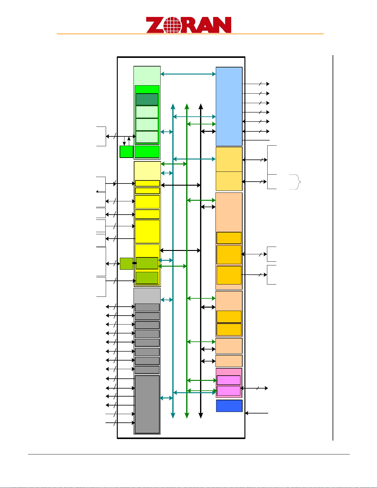
Figure 3: SupraHD-760 Detailed Block Diagram
ZR39760
SADR[13:0], SBS[1:0]_n
SDQM[3:0]
SRAS_n, SCAS_n, SWE_n
SCLK, SCLK_n, SCKE
SDQS[3:0],
SDATA[15:0]
SVREF
Memor y
Interface Unit
(MIF)
16
4
3
3
4
16
Embedded
Processing Unit
(EPC)
MIPS 4Kec
I Cache
D Cache
MMU
EJTAG
Ctlr.
JTAG
Ctlr.
Counters/
Timers
6
Transport
Processing Unit
(TRP)
Xport I /F
Xport Demux
Video Capture
Uni t
HDMI
NTSC/PAL
Decoder
8
Audio
Processing Unit
(APU)
Displ ay
Processor
(DPC)
Graphics
MPEG2 Decode
Uni t
(VDEC)
uController
(MCU)
Sequencer
(MCE)
Flex Bus Unit
(FBU)
MIF BUS (64b)
I2C Ctlr. 1
I2C Ctlr. 2
I2C Ctlr. 3
GPI O
2
2
2
4
IRR
1
I2C0C, I 2C0D
I2C1C, I 2C1D
I2C2C, I 2C2D
GPIO[3:0]
IRR
UART0
2
UART0_TX, UART0_RX
BVCI
Modified
Guest Bus
5
GADR[4:0]
GDAT[7:0]
6
GCS_n[5:0]
1
GWS_ACK
5
GDIR, GOE_n, GI OWR_n, GIORD_n, GWE_n
4
GIRQ[3:0]
CLKIN,
CLKOUT
BVCI/AVCI BUS (64b)
RESET_n
Video I/F
29
13
HDMI_SCL, HDMI_SDA,
HDMI_CEC, HDMI_HPD, HDMI_REXT,
HDMI_D0P, HDMI_D0N, HDMI_D1P,
HDMI_D1N, HDMI_D2P, HDMID2N,
HDMI_CLKP, HDMI_CLKN
TDO, TDI
TCK, TMS
TRST_N, TAPSEL
10
PVCI BUS (64b)
Link List
CLKGEN
DVCXO
PLL
2
BLT
UART1
2
UART1_TX, UART1_RX
ACLK
BCLK, LRCLK
ADATAO[2:0]
ADATAI [2:0]
IEC958
PIXOUT[23:0],PCLK, DEN, OSDP,
AFHSI , AFVSI
HDMI
PHY
VFE_YIN, VFE_CI N,
VFE_CVBS, VFE_REFP, VFE_REFN,
VFE_VCM, VFE_IBEXT, VFE_BG
Unique 128-bit
ID
LVDS Output
19
LVDS_C_P, LVDS_C_N,
LVDS_D[7:0]_P, LVDS_D[7:0]_N
LVDS_REXT
L/R
Audio
DACs
4ADATAO[2: 0]
ADATAI [2]
Shared
with the
I2S
signals
AGC
4
IF_AGC, AGC_SENSE, RF_AGC,
PWM_OUT
Demod
7
IFE_AIMP, IFE_VREFP, I FE_VREFN,
IFE_AINN, IFE_RBIAS, IFE_VCM, IFE_VINBIAS
Smart
Antenna
3
SADATA, GPIOx, GPIO,
8
4
TSO_CLK, TSO_FRAME,
TSO_VALID, TSO_DATA
4
TSI_CLK, TSI_FRAME,
TSI_VALID, TSI_DATA
SPI
5SPI_CLK, SPI _SI , SPI_SO,
SPI_HOLD, SPI_WEN

SupraHD-760-DTS-GEN-v1.0-Preliminary Release
5 CONFIDENTIAL INFORMATION-DO NOT COPY 10/10/06
October 10, 2006 11:23 am
1.3 I/O Options
Figure 4 shows the four major I/O options available:
• video input and output
• audio input and output
Figure 4: I/O Option Dataflows
MIF BUS (64b)
BVCI/AVCI BUS (64b)
PVCI BUS (32b)
8
Audio
Processing Unit
(APU)
Display Processor
(DPC)
Graphics
Video I/F
29
13
10
HDMI
PHY
LVDS Output
8
L/R
Audio
DACs
4
1
2
4
II
6
Iiii i
ii
5B
A
Video Input Options
1. ATSC MPEG2 Transport Stream Input via Serial Transport Port
2. IF interface from ATSC/Cable QAM compatible Tuner
3. Serial Transport output from the integrated Demodulator
4. Uncompressed Digital Video (YUV or RGB Format) via HDMI Port
5. Uncompressed Digital Video (YUV or RGB Format) via 24-bit UDI Port
6. NTSC CVBS Analog Video via NTSC/PAL Decoder Port
Video Output Options
A. Uncompressed Digital Video (YUV or RGB Format) via LVDS Output
B. Uncompressed Digital Video (YUV or RGB Format) via Uncompressed Digital Video Port
Audio Input Options
I. Up to Six (6) channel I2S Input via three (3) I2S Ports
II. Two (2) channel PCM Audio Input via the HDMI Port
Audio Output Options
i. Up to Six (6) channel I2S Output via three (3) I2S Ports
ii. Two (2) channel Analog Output via DAC Output
iii. IEC958 (S/PDIF) Output
1
A
I
i
Video
FE
Transport
Processing Unit
(TRP)
Xport I/F
Xport Demux
Video Capture
Unit
HDMI
NTSC/PAL
Decoder
AGC
Demod
Smart
Antenna
4
7
34

Trouble shooting Guide
1.Power Supply Trouble
Check F1 for 12V
Check F1 and CN10 Check E33
(
470μF/25V
)
for 5v
Check F1 for shortcut Check power output for LDO
OK
Turn on or not
Check the power
supply net follow F1 Turn on
the set
Change LDO
Or The load is OK
Check Pin3 U13
For 350Khz
switch si
g
nal
U13/MP1410ES &
D17/IN5822 Check L9/47μH
Higt Voltage Low voltage
U13/MP1410ES
5thPIn & U13 Check C111/0.01F
Y
N
Y
N
N Y Y
NY
N
YN
NY
OK
Check Mcu
1,power supply
2,Reset
3,Crystal
N Y

2.Display Trouble
2.1 Black
Black Screen
Check 5V for BLON on CN10
Tunn on or not
Turn on
图2
Check Mcu
1,power supply
2,Reset
3,Crystal
Check the cirture for
Q4/MMBT3904
N
N
N
Y
Y
12V inverter input ?
Check the power supply Check the inverter
or self-proofed
N Y
Check U25/SM5964 43th PIN

2.2 White
White Screen
Check signal output of U5/RTD2023B
Check voltage between
U25/SM5964 3thQ24 or
check U25
Check voltage of Q24
Turn to power suppy
trouble shorting
Check LCD or
Panel Connector
Check U5
1,Power supply
2,Time circuit
Check Q24 0~3.3V(5V or 12V),according to the volitage)
N Y
Check
p
ower su
pp
l
y
(
for
p
anel
)
Check voltage of Q24
Check Q24(be care
f
o
r
t
h
e
s
h
o
r
t
in
g
)
Check circuit between
CN8 and CN9
N
N
N
N Y
Y
Y
Y

2.3 Exceptional screen
Exceptional screen
Check voltage for the panel
Check the panel
connector
Check LCD
Check the output net,the
connector
Change the panel
connector
Change LCD
Select the
right panel
volta
g
e
N
Y
N
N
Y
Y
Check U5 For
Power supply & timer circuit
Y
Change/mend the part
circuit
N

3.Audio Trouble
3.1 NoAudio
No Audio
Check audio signal input
Check the
peripheral
audio
devices
U3/TPA1517NE PIN7
11.2V?
N Y
Y
N
Check
p
ower U3 8th
Check
power
supply
for U3
Check the set of volume, mute
Reset
Check signal from C11
Y N
Check
the
speaker
N
Y
Check U25/SM5964
And U25 I/0 interface
(PIN6,12)
Check U3 PIN1 and PIN9 for signal input
YN
Y N
Check U3 PIN4 and PIN6 for
signal output Chekc U21PIN60,61for signal output
Y
N
Check
U3 or
E45/100
Examine and
repair the
output net
between U3
and CN11
Check net
between
U21
PIN60,61
And U3
PIN1,9
Check input audio
input
AV:U21 PIN49,50
PC
下
U21
PIN
53 54
Check
U21
Check the
net
between
Y N
Y N

3.2 TV No Audio
TV no audio, having picture
Check audio and PC AV
N Y
Turn to NO AUDIO
trouble shooting
Check signal ouput of SAW2/M9370M30 PIN1
1. check SAW2
2. check U21 PIN29,30
3. check power supply of U21
4. make sure U21 is damaged
Check the net between SAW2
Pin1and C133/0.01μF
Check C133
Y N

3.3 TVAudio Unormal
Noise and NICAM can’t be detected
Check the audio system
Select the right audio
Search again
Picture is normal?
Check C113/0.01UF、D26、
R140/0 or change SAW2
N
N
Y
Y

4.Function Trouble
4.1 TV
TV can not search/No picture
Check RF signal input
N
Examine
and repair
RF device
Y
Check voltage T1/TDQ-6H3PIN6 for 5V
Examine
and repair
The power
supply net
Y N
Check voltage T1 PIN3 for 0V
Examine
and repair
R267/0Ω
NY
Check I2C signal T1 PIN4,5
Check I2C net
(connect with
U25/SM5964
PIN16,17
N
Y
Check signal T1 PIN11
N
Check the net between
T1 PIN11 and
U21 PIN24,25
;Power supply for U21
Y
Check voltage T1 PIN1 >V
Examine and
repair
The circuit
N
Y
Change
T1/TDQ-6H3
Check voltage T1 PIN9 for 33V
Examine
and repair
33V
circuit
Y N

4.2 PC
Picture not in center Missing color Picture dithering No signal
Auto adjust
Check U5 RGB input
Reset
Y N
Check R,G,B
circuit
Check VS,HS signal
Check OSD setting
Reset
Check
VS.HS
ii
Y N
Check
VS.HS
PC
Table of contents
Other Haier TV manuals

Haier
Haier L47K30B User manual

Haier
Haier NS-L19W2Q-10A User manual

Haier
Haier HTN13R12 User manual

Haier
Haier 29F8A-T User manual

Haier
Haier HT-3718 User manual

Haier
Haier 29FA11-AM User manual

Haier
Haier 21T07 User manual

Haier
Haier HT-3499 User manual

Haier
Haier LE32C430 User manual

Haier
Haier 1407 User manual