2
HALLMARK INDUSTRIES INC
Shallow
Well Jet
Pumps
624 Estes Ave, Schaumburg, IL 60193, USA www.hallmarkind.com
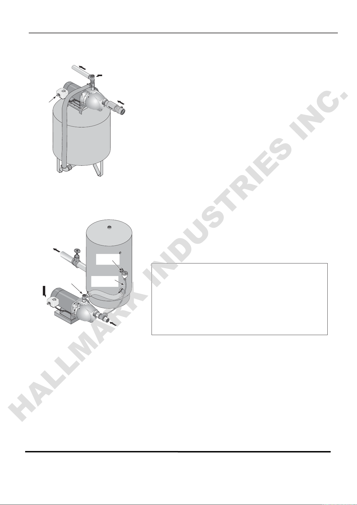
To Household
Water System
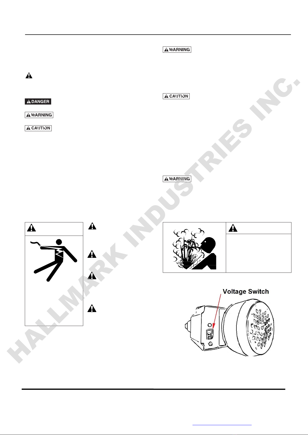
Hazardous
v
oltage
.
Disconnect power to pump before
working on pump or motor.
Pump Priming
Tee with Plug
or Gauge
Drain and removethe old pump. Check the old pipe for
scale,
lime,
rust,etc., and replaceit if necessary.
Install the pump in the
system. Seal
the pipe joints with 1Teflon™
tape
or
aTeflon™
based
pipe joint compound. Make
sure
that all pipe joints
in
the suction pipe areair-tight
as
well
as
water tight. If the suction pipe
can suckair, the pump will not be able to pull water from the
well.
Adjust the pump mounting height sothat the plumbing
connections
do
not put a strainon the pump body.
Support
the pipe sothat the pump
body
does
not takethe weight of piping or fittings.
You havejust completed the well plumbing for your new shallow well jet
pump.
Please
go to
Page
4 for
discharge
pipe and tank connections.
Well Point
(Driven
Point)
Installation
(Figure 1)
Drive the well, using“drive couplings” and a “drive cap”.
“Dri
v
e
fittings” are
threaded
all the way through and allow the pipe
ends
to
butt
against
eachother sothat the driving force of the maul is carried
by the pipe and not by the
threads.
Theordinary fittings found
in
hardware
stores
arenot
threaded
all the way through the fitting and can
collapse
under impact. “Drive fittings” arealso
smoother
than standard
plumbing fittings, making ground penetrationeasier.
Mount the pump
as
closeto the well
as
possible.
Usethe
fewest possible
fittings
(especially
elbows)when connecting
the pipe from the well point to the pump suction port. Thesuction pipe
should be at
least as
large
as
the suction port on the pump (include
a check valve if your pump is not equipped with one –
see Figure
1).
Support
the pipe sothat thereareno dips or
sags
in the pipe, so
it
doesn’tstrainthe pump body, and sothat it
slopes
slightly upward from
the well to the pump (high
spots
can
cause
air
pockets
which can air
lock the pump).
Seal
the pipe joints with Teflon™ tape or aTeflon™
based
pipe joint compound.
J
oints
mustbe air- and water-tight. If the
suction pipe can suckair, the pump cannot pull water from the well. If
one well point
does
not supply enoughwater, considerconnecting
tw
o
or threewell points to one suction pipe.
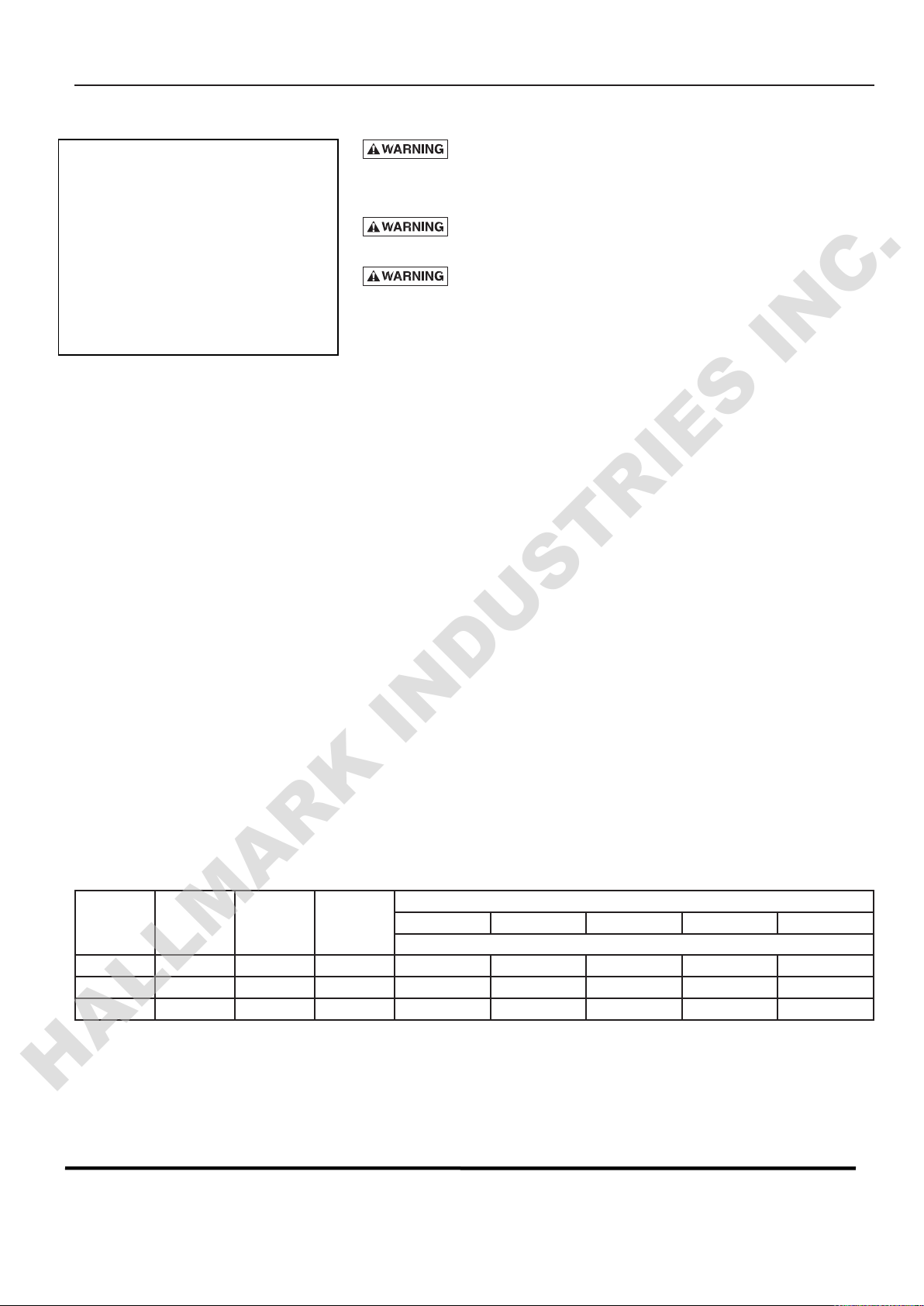
Typical
pump
shown
herein
notto scale
Figure 1: Driven Point Installation
To Household
Water System
Pump Priming
Tee with Plug
or Gauge
You havejust completed the suction piping for your new shallow well jet
pump.
Please
go to
Page
4 for
discharge
pipe and tank connections.
Cased Well
Installation,
2” or Larger Casing
(Figure 2)
Mount the pump
as
closeto the well
as
possible.
Assemble
the foot valve,
strainer,
and well pipe
(see Figure
2). Make
sure
that the foot valve works freely.
Lower the pipe into the well until the
strainer
is five feetabovethe
bottom of the well. It should alsobe at
least
10 feetbelow the
well’
s
water level while the pump is running in order to preventthe pump
from suckingair. Install a
sanitary
well seal.
Figure 2: Cased Well Installation
Priming
Tee and
Plug
Sanitary
Well Seal