Handy Home Products OCOEE User manual

STOP!
STOP!
16684
Call Us First!
DO NOT RETURN TO STORE.
For immediate help with assembly or product information
call our toll free number:
1-800-221-1849
or email:
Our staff is ready to provide assistance
April through October M-F 8:00 AM to 7:00 PM EST
Saturday 8:30 AM to 4:30 PM EST
November through March M - F 8:00 AM to 5:00 PM EST

(This page intentionally left blank.)

01/05/2016
KEEP THIS MANUAL FOR FUTURE REFERENCE
ACTUAL FLOOR SIZE IS 68-1/4 x 36" (173,4 x 91,4 cm)
OCOEE 6' x 3' (182,9 x 91,4 cm)
ASSEMBLY MANUAL 16684
BEFORE YOU BEGIN
IMPORTANT!
READ INSTRUCTIONS THOROUGHLY PRIOR TO BEGINNING ASSEMBLY.
- CUSTOMER SERVICE -
• BUILDING RESTRICTIONS AND APPROVALS
Be sure to check with local building department and homeowners association for speci c restrictions and/ or requirements before building.
• ENGINEERED DRAWINGS
Contact our Customer Service Team if engineered drawings are needed to pull local permits.
• SURFACE PREPARATION
To ensure proper assembly you must build your shed on a level surface. Recommended methods and materials to level your shed are
listed on page 6.
• CHECK ALL PARTS
Inventory all parts listed on pages 4 - 5. Contact our Customer Service Team if any parts are missing or damaged.
• ADDITIONAL MATERIALS
You will need additional materials to complete your shed. See page 3 for required and optional materials and quantities.
A Backyard Products Company
2
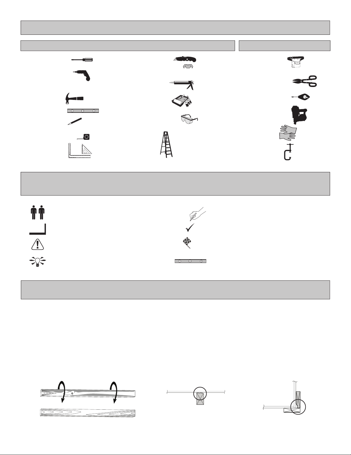
TOOLS
Safety! Always use approved safety glasses during assembly.
OptionalRequired
HELPFUL REMINDER SYMBOLS
Look for these symbols for helpful reminders throughout this manual.
ORIENT LUMBER AND TRIM FOR BEST APPEARANCE
= Assistance Required; two or more people.
= Ensure squareness.
= Important required step or operation.
= Helpful assembly hint.
= Mark part with pencil.
= Beginning of steps for assembly or installation.
= You have nished the assembly or installation.
= Level
❑Gloves
❑C-Clamps
Framing lumber is graded for structural strength and not appearance. Exterior trim is graded for one good side.
Always install the material leaving the best edge and best surface visible. Please remember that these blemishes in no way
negatively affect the strength or integrity of our product. (See Fig. A, B, C.)
A
❑Safety Glasses
❑Tape Measure
❑Paint Tools
❑Ladder
❑Caulk Gun
❑Hammer
❑Level
FINISH
BEGIN
❑Pencil
❑Phillips
Screwdriver
❑Drill / Driver
❑3/8" Drill Bit
❑#2 Philips Drive Bit
❑Tool Belt/
Nail Pouch
❑Chalk Line
❑Nail Gun
• gun nails
❑Tin Snips
(for drip edge)
❑ Square or
❑Utility Knife
❑Shingle Blades
B C

3
COMPLETING YOUR SHED
You will need these additional materials:
OPTIONAL MATERIALS
FOUNDATION OR FLOOR MATERIALS
ADDITIONAL MATERIALS NEEDED
BEFORE YOU BEGIN
DRIP EDGE ..................... 20 Feet
#15 ROOFING FELT
To cover 23 Sq. Ft. of roof area.
1" GALVANIZED ROOFING NAILS.........1/4 Lb
For roong felt.
REFER TO THE BACK OF THIS MANUAL AND THE MANUFACTURER’S INSTRUCTIONS
FOR INSTALLATION OF SHINGLES, DRIP EDGE AND FELT.
• This shed kit includes a complete wood oor frame system and oor decking.
• This shed kit does not include ANY leveling materials.
•See the FLOOR LEVELING section on page 6 for recommended methods and suggested materials to properly level your
oor, as this will vary depending on your specic site.
3-TAB SHINGLES ............................ 1 Bundles
PAINT FOR SIDING .......................... 1 Gallon
Use 100% acrylic latex exterior paint. (2) coats recommended.
CAULK ................................................. 1 Tube
Use acrylic latex exterior caulk that is paintable.
1" GALVANIZED ROOFING NAILS.... 1 Lbs
For shingles.
PAINT FOR TRIM .............................1 Quart
Use 100% acrylic latex exterior paint.
REINFORCED WOOD FLOOR FRAME (OPTIONAL)
IMPORTANT! (The included oor is designed for general use.) Depending on your specic use you may want to construct a heavy
duty oor frame by adding additional oor joists (shown below as shaded). Below is a list of additional materials (not included):
x8
x2 2 x 4 x 8' (5 x 10 x 244 cm) Treated Lumber
Cut lumber to 2 x 4 x 65-1/4" (5 x 10 x 165,7 cm)
3" (7,6 cm) Hot Dipped Galvanized Nails
Optional 9" (322,9 cm)
spacing
Standard 18" (45,7 cm)
spacing
Required to validate warranty
Table of contents
Other Handy Home Products Outdoor Storage manuals


Popular Outdoor Storage manuals by other brands

LIVING AND HOME
LIVING AND HOME 0735940285711 user guide

USP
USP DURAMAX 10 Ft x 8 Ft StoreMax Plus owner's manual

rollaway container
rollaway container ARPCA24 manual

Duratuf
Duratuf GL105 Assembly instructions

Viking
Viking SD5300SS Use & installation guide

USP
USP DURAMAX Apex Pro 10.5 Ft x 8 Ft 40116 owner's manual


