Hangzhou Gubei Electronics WT1HB12 User manual

Wi-Fi Module User Manual
Model: WT1HB12
V 1.5
1. Product Overview
1.1. Introduction
BroadLink WT1HB12 is the industrial leading 2.4Ghz 802.11 b/g/n embedded Wi-Fi module
which delivers unmatched performance and codeless development in a compact package,
providing a quick, easy and cost effective way for developers and manufacturers to add Wi-
Fi connectivity for home automation, lighting control, energy efficiency and other IOT
applications.
WT1HBS12 combines a 2.4Ghz 802.11 b/g/n radio transceiver with MAC, baseband
processing and optimized Wi-Fi protocols, configuration profile and network stack It
supports UART communication with other devices and can be widely used in applications
like smart home, remote monitoring and medical care. It is an ideal solution for developers
and manufacturers with limited RF and embedded programming expertise as it significantly
reduces RF design time and removes the burden of testing and certification.
WT1HBS12 integrates a 32-bit RISC processor and an 8 Mbit flash which is capable for most
of control-type IoT application.
RF
receiver
RF
transmitter
Baseband
MAC /
Packet
buffer /
security
engine
UART
System
control
RF_IN
RF_OUTP
RF_OUTN
UART
GPIO/LED
Figure 1. WT1SBSL block diagram
2. Specifications
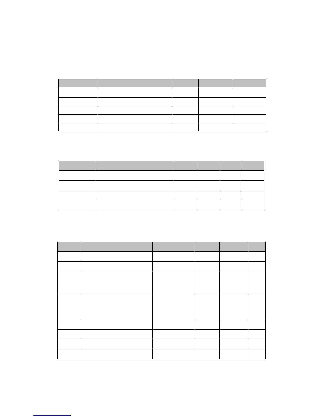
2.1. Absolute maximum ratings
Symbol Description Min. Max. Units
Ts Storage temperature -40 125
℃
TAMBIENT Ambient Temperature -10 70 ℃
Vdd Supply voltage 0 16 V
Vio Voltage on IO pin -0.28 3.63 V
VESD HBM (human body model) 2000 V
2.2. Power Characteristics
Symbol Rating MIN TYP MAX Unit
VDD 12V Supply Voltage 9 16 V
VDD33 3.3V Supply Voltage 2.97 3.3 3.63
VDD12 1.2V Supply Voltage 1.14 1.2 1.26 V
VDD15 1.5V Supply Voltage 1.425 1.5 1.575 V
2.3. DC characteristics
Symbol Parameter Conditions MIN MAX Unit
VIL Input Low Voltage LVTTL -0.28 0.6 V
VIH Input High Voltage 3.5 5.5 V
VT-
Schmitt Trigger Negative
Going
Threshold Voltage LVTTL
0.68 1.36 V
VT+
Schmitt Trigger
Positive Going Threshold
Voltage
1.36 1.7 V
VOL Output Low Voltage |IOL| = 1.6~14 mA -0.28 0.4 V
VOH Output High Voltage |IOH| = 1.6~14 mA 33.6 V
RPU Input Pull-Up Resistance PU=high, PD=low 40 190 KΩ
RPD Input Pull-Down Resistance PU=low, PD=high 40 190 KΩ

2.4. Current consumption
Description
Performance
TYP Unit
Sleep mode 2mA
IDLE mode 25 mA
RX Active, HT40, MCS7 50 mA
RX Power saving, DTIM=1 8mA
TX HT40, MCS7 @15dBm 70 mA
TX CCK, 11Mbps @18dBm 80 mA
Note: All result is measured at the antenna port and VDD is 12V
2.5. Dimensions
Module
Tolerance: (L±0.2)*(W±0.2)*(H±10%) (unit: mm)

Shield case
Tolerance: (L±0.1)*(W±0.1)*(H±0.1) (unit: mm)

3. Module Interface
3.1. PIN Definitions
PIN PIN NAME DESCRIPTION TYPE NOTE
Pin1 UART0_TX UART0 send data O
UART0
Only used for UART
DCDC works when EN >
1.5V
Pin2 UART0_RX UART0 receive data I
Pin3 EN Enable DCDC I
Pin4 GND GND POWER
Pin5 VDD Power input POWER
1. The TX and RX of UART0 are used for communication with external processor. Please
refer to Chapter 2.3 DC Characteristics for more information of output power level for
UART.
2. The module has built-in RC reset and watchdog circuit.
3.2. PCB Antenna
The module supports PCB antenna. Within the range of 2.4-2.5GHz, the antenna output S11 is
less than -10dB and gain of antenna is about 2dBi.

The actual performance of S11 may vary due to PCB production and dielectric constant
difference of FR-4 board.

Appendix A Glossary(Quentin respible)
ADC Analog‐to‐DigitalConverter
AES AdvancedEncryptionStandard
ANT Antenna
AP WirelessAccessPoint
BPSK BinaryPhaseShiftKeying
DBPSK Differential binary phase shift keying
DC Direct Current
CCK ComplementaryCodeKeying
CDM ChargeDeviceModel
DHCP Dynamic Host Configuration Protocol
CMOS ComplementaryMetalOxideSemiconductor
DNS Determination of non-significance
DQPSK Differential quadrature phase shift keying
DSSS Demand assigned signaling and switching subsystem
DTIM Digital Transmission Interface Module
EMSP Enhanced Modular Signal Processor
ESD Electrostatic Discharge
EVM Error Vector Magnitude
FCC Federal Communications Commission
FER Floating Error
GND Ground
GPIO General Purpose Input/Output
HBM Human body model
IEEE Institute of Electrical and Electrionics Engineers
IO Input/Output
IOT Individual operation test
IPv4 Internet Protocol version 4
LED Light-emitting diode
LVTTL Low Voltage Transistor Transistor Logic
MAC Medium Access Control layer
MCS Modulation and coding scheme
MCU Microcontroller Unit
MIMO Multiple-Input Multiple-Output
MSL Multilayer Switching Protocol
NC Numerical Control
NRST Negative Reset
OFDM Orthogonal Frequency Division Multiplexing
OSC Oscillator
PCB Printed Circuit Board
PIFA Planar inverted F antenna
QPSK Quadrature Phase Shift Keyin
RC Resistance- capacitance
RF Radio Frequency
RISC Reduced Instruction Set Computer
RoHS Restriction of Hazardous Substances
RX Receiver
SDIO Serial Digital Input/Output
SoC System on Chip
SPDT Single-Pole Double-Throw
SPI Serial Peripheral Interface

STA Spanning Tree Algorithm
TCP Transfer Control Protocol
TKIP Temporal Key Integrity Protocol
TX Transmitter
IP Internet Protocol
UART Universal Asynchronous Receiver/Transmitter
UDP User Datagram Protocol
UFL
a miniature coaxial RF connector for high-frequency signals
manufactured by Hirose Electric Group
VSWR Voltage Standing Wave Ratio
WEP Wired Equivalent Privacy
WEPA Welded Electronic Packaging Association
WEP64 64 bit Wired Equivalent Privacy
WEP128 128 bit Wired Equivalent Privacy
WPA2 Wi-Fi Protected Access 2
XTAL External Crystal Oscillator
QAM Quadrature Amplitude Modulation
802.11 b/g/n The IEEE 802.11 b/g/n

This device complies with Part 15 of the FCC Rules / Industry Canada licence-exempt
RSS standard(s). Operation is subject to the following two conditions: (1) this device
may not cause harmful interference, and (2) this device must accept any interference
received, including interference that may cause undesired operation.
Le pr
é
sent appareil est conforme aux CNR d'Industrie Canada applicables aux
appareils radio exempts de licence. L'exploitation est autoris
é
e aux deux conditions
suivantes : (1) l'appareil ne doit pas produire de brouillage, et (2) l'utilisateur de
l'appareil doit accepter tout brouillage radio
é
lectrique subi, m
ê
me si le brouillage est
susceptible d'en compromettre le fonctionnement.
Changes or modifications not expressly approved by the party
responsible for compliance could void the user's authority to operate the
equipment.
This equipment has been tested and found to comply with the limits for
a Class B digital device, pursuant to part 15 of the FCC Rules. These
limits are designed to provide reasonable protection against harmful
interference in a residential installation. This equipment generates
uses and can radiate radio frequency energy and, if not installed and
used in accordance with the instructions, may cause harmful interference
to radio communications. However, there is no guarantee that interference
will not occur in a particular installation. If this equipment does cause
harmful interference to radio or television reception, which can be
determined by turning the equipment off and on, the user is encouraged
to try to correct the interference by one or more of the following
measures:
—
Reorient or relocate the receiving antenna.
—
Increase the separation between the equipment and receiver.
—
Connect the equipment into an outlet on a circuit different from that
to which the receiver is connected.
—
Consult the dealer or an experienced radio/TV technician for help.
MPE Requirements
To satisfy FCC / IC RF exposure requirements, a separation distance of 20 cm or more
should be maintained between the antenna of this device and persons during device
operation.
To ensure compliance, operations at closer than this distance is not recommended.
Les antennes installées doivent être situées de facon à ce que la population ne puisse
y être exposée à une distance de moin de 20 cm. Installer les antennes de facon à ce
que le personnel ne puisse approcher à 20 cm ou moins de la position centrale de l’
antenne.
La FCC des éltats-unis stipule que cet appareil doit être en tout temps éloigné d’au
moins 20 cm des personnes pendant son functionnement

Region Selection
Limited by local law regulations, version for North America does not have region selection
option.
Information for the OEM Integrators
This device is intended for OEM integrators only. Please see the full grant of
equipment document for restrictions.
Label Information to the End User by the OEM or Integrators
If the FCC ID of this module is not visible when it is installed inside another device,
then the outside of the device into which the module is installed must be label with
“
Contains FCC ID: 2ACDZ-WT1HB12 and IC: 21239-WT1HB12
”
Table of contents
Popular Network Card manuals by other brands


Transition Networks
Transition Networks N-FXE-xxx-01 user guide

Lenovo
Lenovo 30221CU - H230 CORE2DUO 500GB Desktop Notice

Planet Networking & Communication
Planet Networking & Communication WL-3560 user manual

Linksys
Linksys EC2T Quick installation

Allied Telesis
Allied Telesis AT-2701FX datasheet

Inventec
Inventec CP-108 user manual

Inetcam
Inetcam Mobile Gateway user guide

Pioneer
Pioneer AirTies 4920 installation guide

D-Link
D-Link AirPro DWL-6000AP manual

Sierra Wireless
Sierra Wireless AirCard 555 Wireless user guide

deXlan
deXlan Wireless LAN PC Card 11Mbps user guide

Sierra Wireless
Sierra Wireless AirCard 555 Wireless installation guide