HANSCRAFT Evolution 25 Service manual


1. Introduction
2. Specifications
3. Dimension
4. Installation
5. Electrical Wiring
6. Initial Startup of the unit
7. Operation
8. Maintenance
9. Troubleshooting
10. Explode diagram
INDEX
PO OL HE A T PUM P

ATTENTION
Thank you for using swimming pool heat pump for your pool heating, it will heat your
pool water and keep the constant temperature when ambient temperature at +7℃ to 40℃
In order to offer qualified, reliable and flexible heat pump unit to our customer, please read
this manual carefully before installing, operating and troubleshooting, then process accordingly.
This manual includes all necessary information
HANSCRAFT
● The heat pump unit must be installed by qualified technicians from after-sales
center or authorized distributor.
● Operating and maintaining according to recommended time and frequency on
the manual.
● Use only standard spare parts.
!
1.Introduction
PO OL H E A T P U M P
01

02
2. Specifications
Above data is subject to modification without notice,
please take the nameplate as standard.
PO OL H E A T P U M P
2.1 Design,R410A,HEATING ONLYHorizontal
Horizontal design, ABS Cabinet
Model Evolution 25 Evolution 40 Evolution 60
* Heating Capacity at Air 27℃, Water 27 , Humidity 80%℃
Heat Output (kW)
Power Consumption (kW)
COP
* Heating Capacity at Air 15℃, Water 26 , Humidity 70%℃
Heat Output (kW)
Power Consumption (kW)
COP
* General data
Voltage
Rated Current (A)
Fuse Current
Advised pool volume
(with pool cover)
Advised water flux
Water Pressure Drop
Condenser
Compressor type
Water pipe in-out
Fan Speed
Noise level(10m)
Noise level(1m)
Refrigerant
* Dimension/ Weight
Net Weight
Gross Weight
Net Dimension
Packing Dimension
6.8 10 13
1.09 1.60 2.07
6.25 6.25 6.25
4.3 6.5 8.2
1.02 1.48 1.86
4.2 4.4 4.4
4.7 7.0 9.0
10A 15A 20A
220-240V/50Hz/1PH
15-25m³ 25-35m³ 30-60m³
2.5~3.7m /h³ 2.8~5.6m /h³ 3.5~7.1m /h³
12KPa 12KPa 15KPa
Titanium in PVC
Rotary/R410a
50mm
830~870RPM
40dB(A) 43dB(A)
47dB(A) 48dB(A)
46dB(A)
40dB(A)
800g 1100g 1200g
32kg 37kg 61kg
37kg 42kg 68kg
1030*335*560mm 1025*350*620mm
1080*360*610mm 1120*380*665mm

03
3. Dimension
NOTE: The factory only provides the heat pump unit. The other items in the illustration are necessary
spare parts for the water system which are provided by users or installers.
4. Installation
4.1 Installation illustration
PO OL H E A T P U M P
Unit : mm
A
B
C
D
E
F
G
H
I
Models
302
622
288
332
988
230
103
557
98
326
655
306
350
1026
340
108
620
92
EVOLUTION 60
EVOLUTION 25
EVOLUTION 40

ATTENTION:
Please follow these steps when operating the first time :
1.Open valve and charge water
2.Make sure that the pump and the water-in pipe have been filled with water
3.Close the valve and start the unit
4.2 Installation
(1) The heat pump unit must be installed by professional technicians .otherwise unit may be damaged or body injured,
even dead
(2) The unit is designed for outdoor location with good ventilation. Recirculation of cold discharge air back into
evaporator coil will greatly reduce heating capacity and efficiency of the unit, which will void the compressor
warranty.
(3) The unit can be installed almost anywhere in the outdoors.To get a good performance ,it needs to meet the three
factors :
a) Good ventilation
b) Stable and reliable power supply
c) Recycled water system
The difference from gas water heater, it should not bring environmental pollution or have the installing problems
in-windy areas.
(4) The unit should not be installed in a limited air ventilation area ,or placed in a bush where it will block the air inlet .
These location deny the unit of a continuous source of fresh air .When seasons changing ,it may stick leaves on
the evaporator coil ,thereby reducing its efficiency and impact of its service life .
(5) For indoor installation, please consult more instruction from technicians.
(6) When install a bypass, it should be not exceed 30% of nominal flow rate
(7 Must make Water level higher than the circulation pump location.
(8) Below picture show the minimum required distance on each side of pool heat pump unit.
Air inlet
Air outlet
!
PO OL H E A T P U M P
04
05
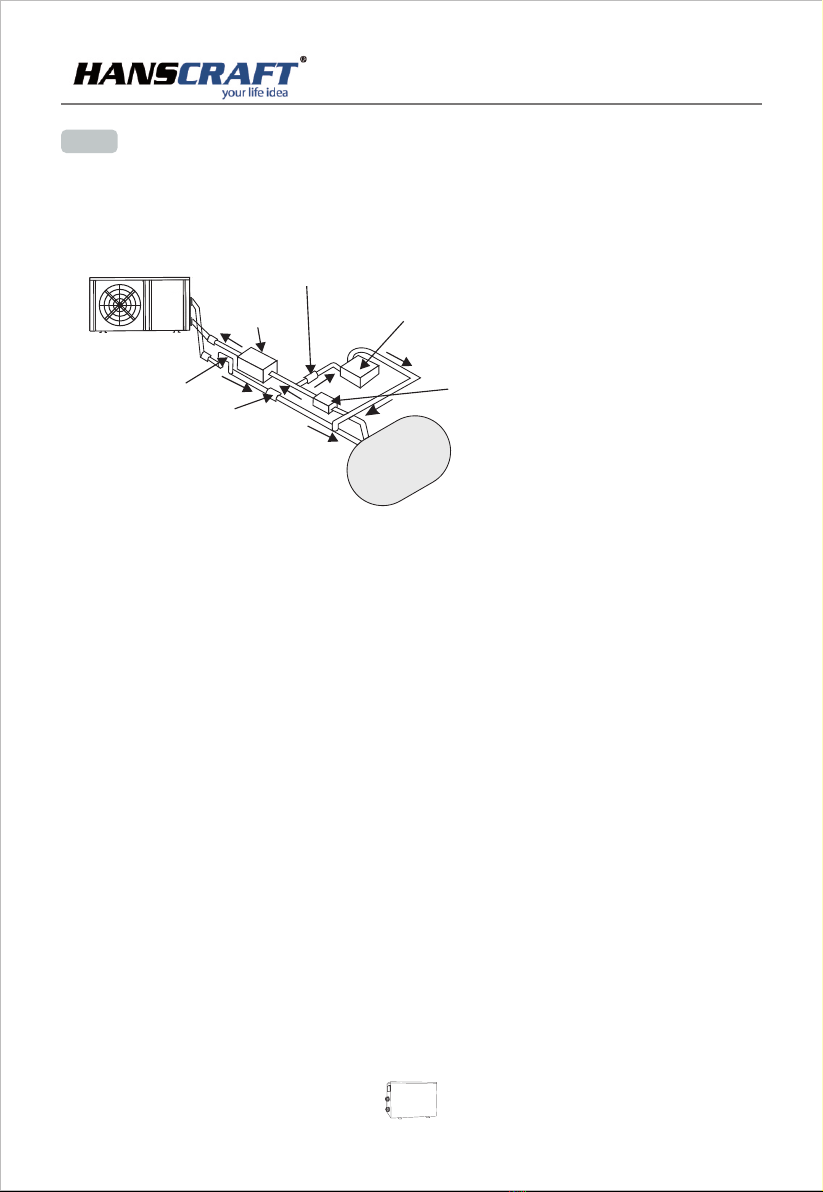
4.3 's instruction to your system is also critical to the heater's life.The location of chemical
If an automatic chlorinator or brominates is used, it must be located downstream of the heater.
A trap must be installed between the chlorinator and the heater to prevent chlorine return into the
heat pump. (See below pictures)
Pressure-type Chlorinator or Brominator
P-trap
Filter Chlorinator
Check-valve
Water pump
Check-valve
(1) Typically, the pool heat pump unit should be installed aside the pools, less than 7.5 meters distance. If it is
installed farther away, the pipeline system will cause greater heat loss. The most of pipeline are installed under
ground ,although the pipeline system has to do thermal insulation ,but tunnels and the soil around will still occur
heat exchange ,for example,each 30 meters ( 15 meters to and from the pump=30 meters total),unless the ground
is wet or the water table is high.A very rough estimate of heat loss per 30 meters is 0.6KW per hour (2000BTU) for
every 5℃ surrounding the pipe,which translates to about 3% to 5% increase in run time.
(2) To get the best heat exchange of heat pump unit, it should be matched the normal rate of water flow
recommended in specification sheet.
(3) It is required to increase the discharge pipe to prevent freezing in cold season ,to put “T” fitting and ball valve to
facilitate changing the water in winter or emptying the water out of system to prevent freezing when HP stop
operating at the ambient temperature below zero ,otherwise the unit may be damaged .
(4) It is suggested to install the quick adaptor in front of water in-out connection, which could discharge water easily
to prevent water freezing, and be convenient for maintenance and service.
(5) When unit running ,there will be some condensation water discharged from the bottom ,please hold the
drainage nozzle (accessory ) into the hole and clip well ,and then connect a pipe to drain the condensation water out.
(6) If water pressure is over 10 KPA ,or water flow rate is more than 11 cubic meters through heat exchanger ,it is
necessary to install the by-pass pipe in water system.
PO OL H E A T P U M P
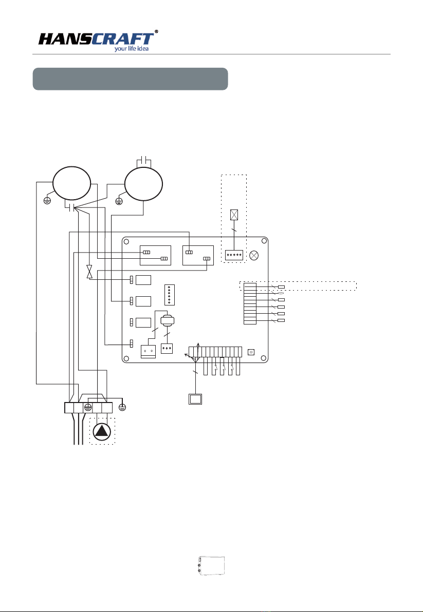
wimming pool heat pump wiring diagramS
5. Electrical Wiring
* The dotted line part are only used in some models
RUN/POW
SINGLE-WATER PUMP
LN1
YLW/ G R N
2
Transformer
2
2
POWER 220-240V/50Hz
OUTDOOR MOTOR
RED
OR G
BL K
S BL K
CO M P R ES SO R
CAPACITOR
R WH T WHT
4-WAY VALVE
BL U
BLU
BRN
BRN
BL U
BL K
BLU
C RE D
RED
BLU
RED
5
Ele ctro n ic Exp ansi o n Valv e
LED
OU T2
OUT1
OUT3
OUT4
OUT5
AC-N
CN1
CN2
3
Rem ote sw i tch
Low v olta g e swit ch
Rem ote co n trol ler
Hig h volt a ge swi tch
Pha se seq u ence p rote c tion
CN3
SW1
YLW/ G R N
YLW/GRN
BRN
BLU
YLW
12V
ENT
GND
GND
GN D
GN D
GND
GN D
KYIN
FS
LP
HP
PP
2
2
2
2
2
2
Wat er out l et coi l temp e ratu r e sens or
Wat er inl e t coil t empe r atur e senso r
H coi l temp e ratu re sen s oreat ing
Amb ient emp erat u re t sen sor
Coo ling c o il tem pera t ure se n sor
Ref rige r ant re turn t e mper a ture s enso r
CN4
GN D
GND
GND
GND
GND
GND
T6
T5
T4
T3
T2
T1
COMPRESSOR
Programming
PC Board
FAN CAPACITOR
Wat er f w swi tch
lo
3
4
3
4
Evolution 25 / Evolution 40
PO OL H E A T P U M P
06

07
PO OL H E A T P U M P
Evolution 60
Swimming pool heat pump wiring diagram
RUN/POW
LN1
YLW/ G R N
2
Transformer
2
2
RED
ORG
BLK
S BL K
R WH T
WHT
BL U
BRN
BR N
BL U
RE D
C RE D
BL U
RED
5
El ec tr onic Ex pa ns io n Valve
LE D
OU T 2
OU T 1
OU T 3
OU T 4
OU T 5
AC -N
CN 1
CN 2
YLW/GRN
YLW/GRN
AC CO NT AC TO R
BL U
BRN
4- W A Y V ALV E
3
Remote switch
Lo w vo lt age swi tc h
Re mo te c ontro ll er
Hi gh v ol tage sw it ch
Phase sequence protection
CN 3
SW 1
BR N
BL U
YL W
12V
ENT
GND
GND
GND
GND
GND
GND
KYI N
FS
LP
HP
PP
2
2
2
2
2
2
Wa te r ou tlet co il t em pe ra ture se ns or
Wa te r in let coi l te mp er at ure sen so r
H co il t em perat ur e se ns orea ti ng
Am bi en t em pe ra ture t sen sor
Co ol in g coil te mp er at ur e senso r
Re fr ig erant r et ur n te mp eratu re s en so r
CN 4
GND
GND
GND
GND
GND
GND
T6
T5
T4
T3
T2
T1
SINGLE-WATER PUMP
POWER 208-230V/60Hz
Pr o g r amm i n g
PC Board
BL U
BLU
CO M PRE S SO R
CA P ACI T OR
FA N C APA C IT O R
Water f w switch
lo
3
4
3
4
O U T D O O R M O T O R
C O M P
* The dotted line part are only used in some models
PO OL H E A T P U M P
Note: Please make sure the water pump is running in circulation with adequate rate of water flow.
Startup Procedure after Installation is completed, and please follow these steps:
(1)Turn on your filter pump ,check water leaks and verify flow of swimming pool
(2)Turn on the electrical power supply to the unit, then press the key ON/OFF of wire controller, it should start in several
seconds.
(3)After running a few minutes make sure the air ventilation from the side (top) of the unit is cooler ( Between 5℃ and 10 ℃)
(4)When turn off the filter pump , the unit should also turn off automatically , if not, then adjust the flow switch
(5)Allow the unit and pool pump to run 24 hours per day until the water reaches the desired temperature .When the
temperature reaches the setting value ,the HP unit will shut down ,when the pool temperature drops more than 1℃,please
restart (as long as HP unit is running )
Water Flow Switch:
It is equipped with a flow switch for protecting the HP unit running with adequate water flow rate .It will turn on when the
pool pump runs and shut it off when the pump shuts off. If the pool water level higher than 1 m above or below the heat
pump's automatic adjustment knob, your dealer may need to adjust its initial startup.
Time Delay:
HP unit should be equipped with a 3-minute built-in solid-state re-start delay protection. Time delay control is an integral
part of the circuit control, it can eliminate restart cycling and contactor chatter.
The time delay will automatically restart the HP unit approximately 3 minutes after each control circuit interruption .Even a
brief power interruption will activate the solid state 3 minute restart delay and prevent the unit from the starting until the 3
minutes countdown is completed.
6. Initial Startup of the unit
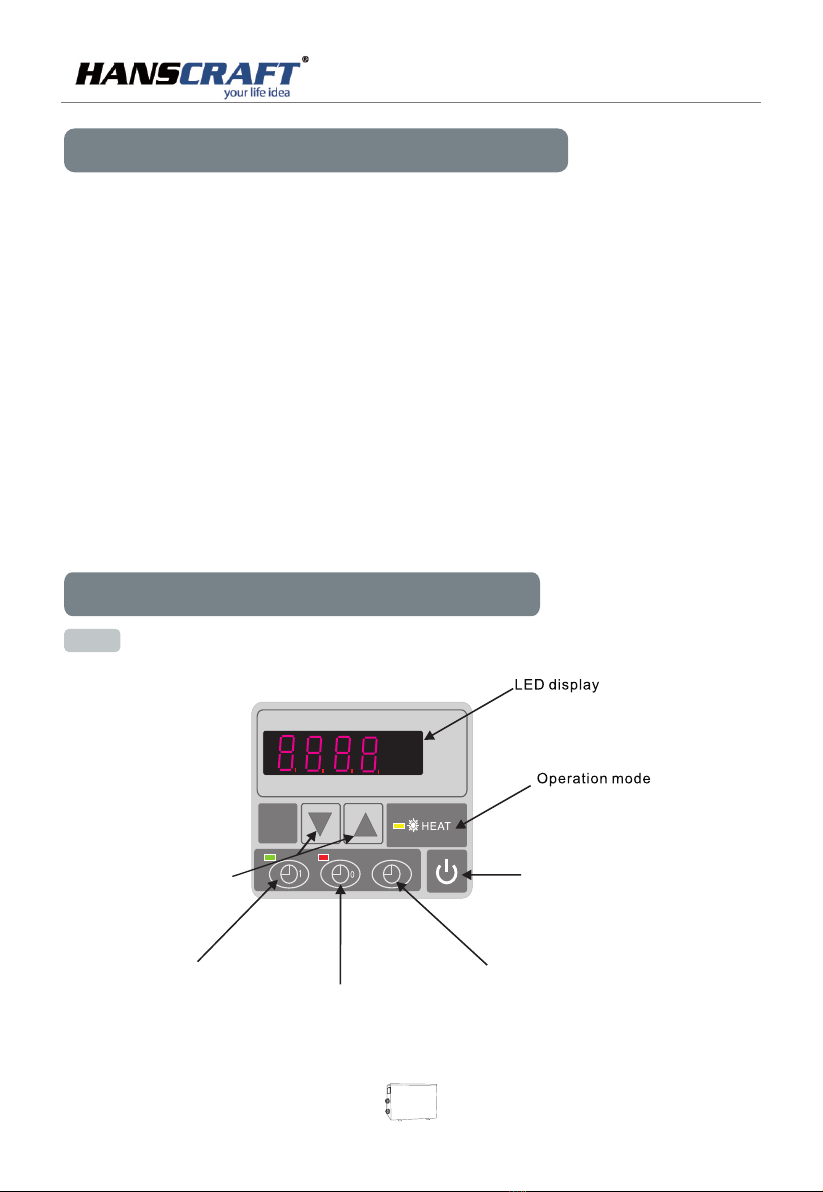
7.1 The functions of LED wire controller
7. Operation Heating Only
ON/OFF
Up and down button
Timer on b utton
Timer off button
Time
button
display
08
09
PO OL H E A T P U M P
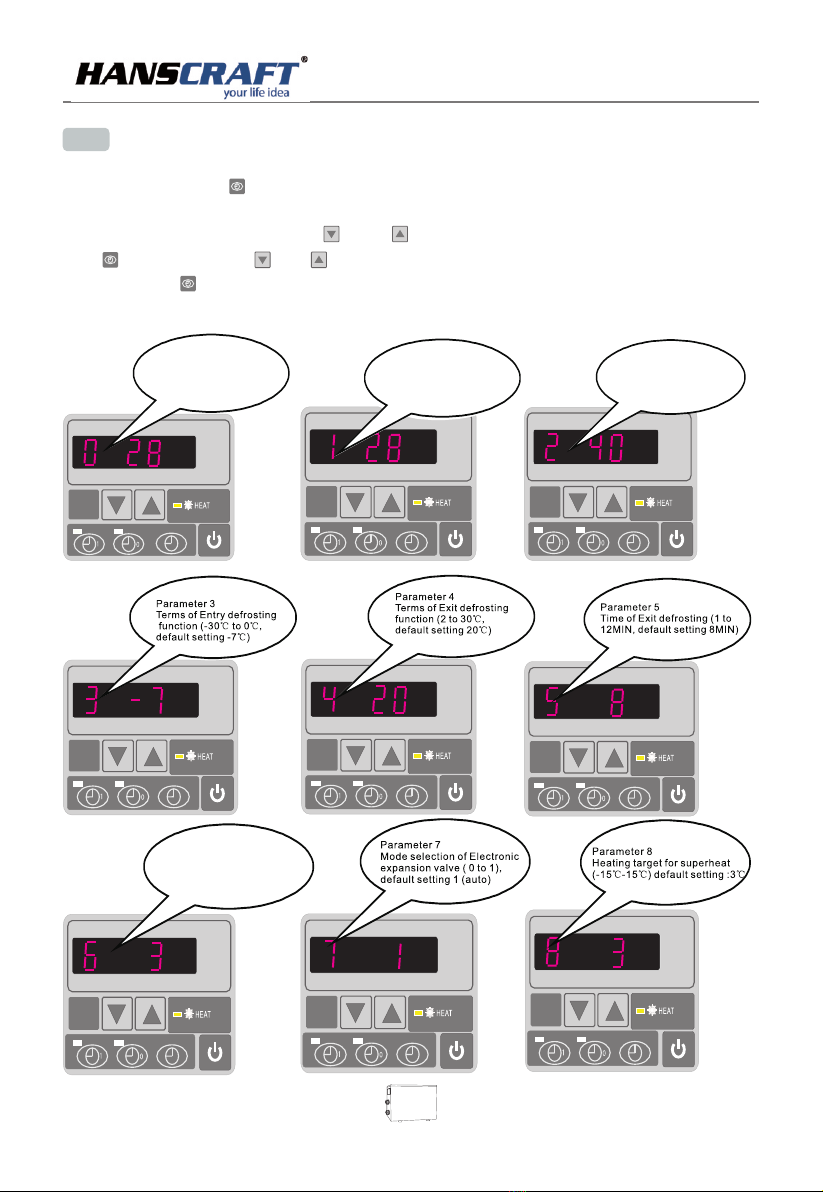
Parameter 2
Total working time of
compressor after frosting
(30-90MIN ,default
setting : 40MIN)
Parameter 0
To set the entering water temp.
under cooling mode (15-35℃,
default setting:28℃)
Parameter 1
To set the entering water
temp. under heating mode
(15-40℃, default
setting:28℃)
7.2 How to set operation parameter
(LED display wil show real time if HP unit is switched off.)
(1) Press and hold in for 5 seconds to enter operating parameter setting interface.
(2) Under parameter setting, press and to choose parameter below from “0” to “A”, press
again then press or to start setting parameters(see operation parameter table)
and press to confirm; Leave it 8 seconds,,LED will display water in temperature(under
running) or current time(until stops).
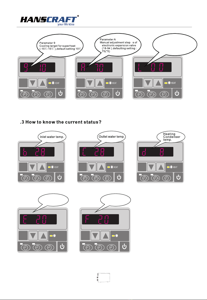
Parameter 6
Mode:0 Heat,1 Heat and Cool
Default setting:0
10
PO OL H E A T P U M P
10
HEAT
10
HEAT
Gas return temp. Ambient temp.
7
Parameter L
Mode:inlet water
temperature correction
Default setting 00
PO OL H E A T P U M P
10
HEAT
10
HEAT
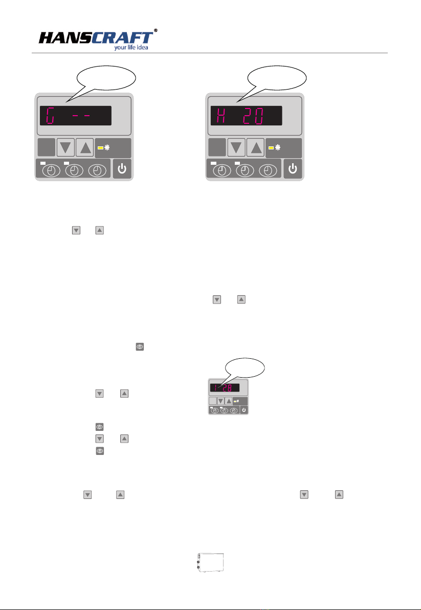
Cooling Condenser
temp.
Actual steps of
electronic
expansion valve
(1) Press or to check water -in/water-out/heating condenser
/back gas/ambient temperature.
(2) When the unit is switched off, current time is displayed.
A. Under running status,
(1) Under current heating mode, only press or to adjust heating water temperature.
B. Under standby status,
(1) Press and hold in for 5 seconds until parameters flash to enter operating setting
(2) Press or to reach Parameter 1 ,
(3) Press again.
(4) Press or to set temperature.
(5) Press to confirm and wait for 8 seconds. Machine will reset new temperature.
7.4 Water temperature setting:
10
10
MODE
HEAT
Param et er 1
To set the en te ri ng w at er
temp. u nd er h ea ti ng m ode
(15-3 5℃, de fa ul t
setti ng :2 8℃)
7
5 seconds 5
seconds
.5 Locking setting
Long press and to lock the parameters, Press and for
again to unlock
11

PO OL H E A T P U M P
6
press the again to store the new data.
7
Press to set the time for HP start to run ,and press or to adjust .
again to store the new data.
Press to set the time for HP stop running, press or to adjust .
then, press again to store the new data.
7.
7.
Time setting:
Press to set the time, and press and to adjust the time
Timer on setting
the time
Press the
7.8 Timer off setting
the off time
1
0
1
0
12
7.10 System reset function
Press and at the same time for 10s, parameter from “0” to “L” to be reset to default.
7.9 Cancel Timer Function
Press or first, then press to cancel timer on or timer off setting.
10
13
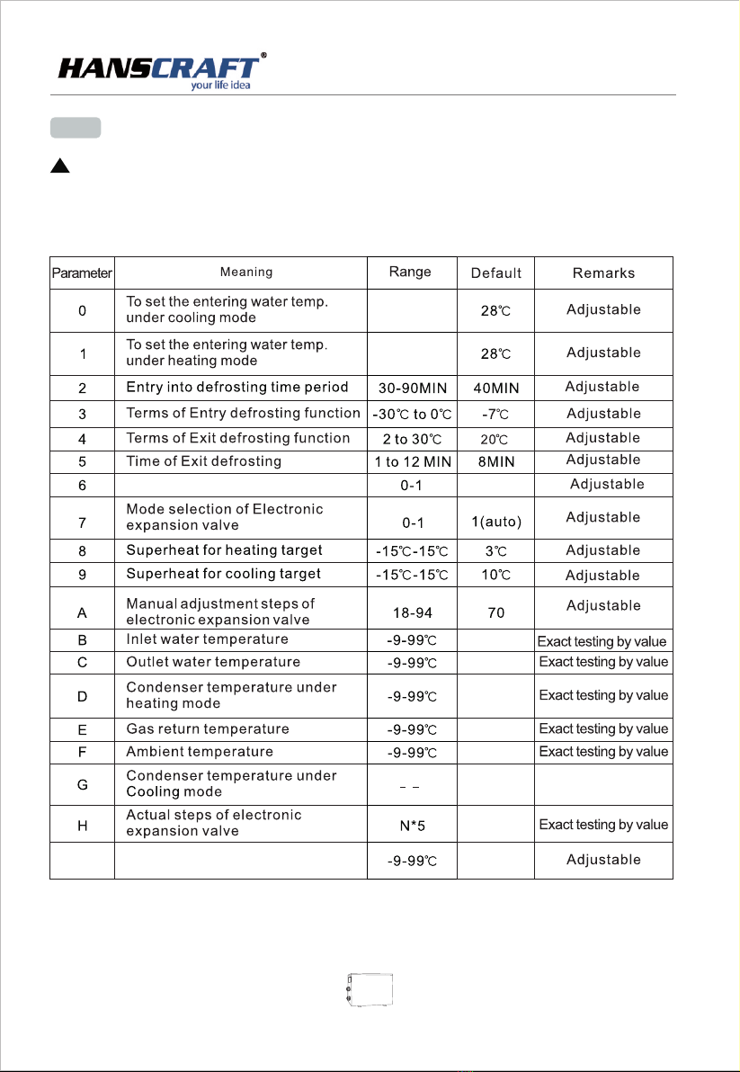
7.4 RUNNING DATA SETTING
Remarks :
(1) LED wire controller can operate the water pump after connected additional cable to the pump device in the position
of “WATER PUMP” terminal accurately .
(2) It is necessary to put an extra 3-phase transfer device for 3 phase water pump.
ATTENTION:
HP running parameters must be checked after installation and before first used.
When the LED on, it will displays water inlet temperature.
When the LED off, it will displays "OFF".
When the LED on, the water temp could be changed.
!
0 ( Heat)
/
15-35℃
15-40℃
PO OL H E A T P U M P
Mode:0 heat,1 heat and cool
LInlet water temperature
correction

(1) You should check the water supply system regularly as to avoid the air entering the system
and occurrence of low water flow, because it would reduce the performance and reliability
of pool heat pump unit.
(2) Clean your spas and filtration system regularly to avoid the damage of the unit as a
result of the dirty of clogged filter.
(3) Keep the HP unit dry, clean, well-ventilated and always clean air side of the heat exchanger,
which can maintain a good heat exchanger and energy saving.
(4) Only a qualified service technician is allowed to operate pressure of the refrigeration system.
(5) Check power cable connection, if heat pump starts to operate abnormally, you should turn
it off and contact with qualified technicians.
(6) You should the water from water pump and other water system, to prevent from the
freezing damage in winter seasons.
(7)
(8)
.
drain
The heat pump and all associated pipe work must be drained down during winter or freezing
conditions.
Always flush with clean water and check thoroughly before recommissioning
the heat pump
WARNING
(1) .
(2) If you are not familiar with your water filtration system and heater
(a) Do not try to adjust, consult the professional dealer.
(b) Before use, please read the Installation and User's Guide.
Note: power supply before
Incorrect installation could result in personal injury.
Do not adjust internal control
TURN OFF any maintenance work
8. Maintenance
9. Troubleshooting guide
PO OL H E A T P U M P
14
15
Note:1.If the LED display the high and low pressure protection three time in half an hour,
2.If the LED display the "EE4"
Above those matter,you can cut off the power and restart the unit again or take it to maintain
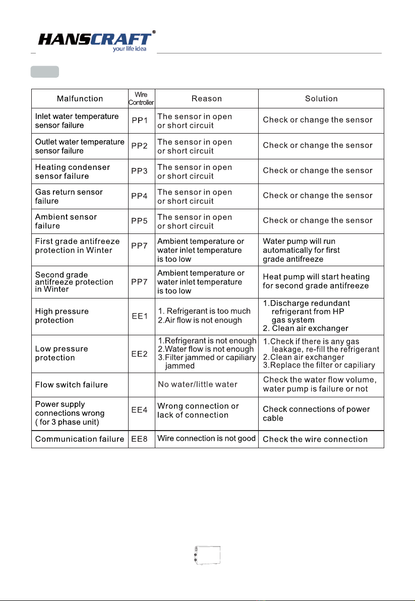
9.1 Error code display on LED wire controller
PO OL H E A T P U M P
ON

Malfunctions Observing Reasons Solution
Heat pump
is not running
LED wire controller
no display No power supply Check cable and circuit breaker
if it is connected.
LED wire controller
displays the
actual time
Heat pump under
standby status
Startup heat pump to run
LED wire controller
displays actual
water temperature
the
1. water temperature is
reaching to setting value
HP under constant
temperature status
2. Heat pump just start to run
3. under defrosting
,
1. verify water temperature setting
2. Startup heat pump after a few minutes
3. LED wire controller should
display “Defrosting”
Water
temperature
is cooling when
HP runs under
heating mode
LED wire controller
displays actual
water temperature
and no Error code
displays
1. choose the wrong mode
2. figures show defects
3. Controller defect
1. adjust the mode to proper running
2. replace the defect LED wire controller,
then check the status after changing the
running mode,verifying the water inlet
and outlet temperature
3. replace defect main controller
Short running LED displays actual
water temperature
no Error
code displays
,
1. fan NO running
2. air ventilation is not
enough
3. refrigerant is not enough
1. Check the cable connections between
the motor and fan if necessary,it
should be replaced.
2. Check the location of heat pump unit,
and eliminate all obstacles to make good
air ventilation
3. Replace or repair the heat pump unit
,
Water stains Water stains on
heat pump unit
1. concreting
2. water leakage
1. No action
2. check the titanium heat exchanger
carefully if it is any defect
Too much ice
on evaporator
Too much ice
on evaporator
1. air ventilation is
not enough
2. refrigerant is not enough
1. check the location of heat pump unit
and eliminate all obstacles to make
good air ventilation
2. replace or repair the heat pump unit
,
9.2 Other Malfunctions and Solutions ( No display on LED wire controller)
PO OL H E A T P U M P
16
In accordance to WEEE Directive (Waste from Electrical and Electronic Equipment Directive)
2002/96/EC this equipment should not be disposed of in the normal waste stream.

10.Exploded Diagram
PO OL H E A T P U M P
17
18
No. No.
Name of parts Name of parts
top cover
back grill
evaporator
Pillar 1
Pillar 2
Left grill
Pillar 3
Upside frame
Fan bracket
Fan motor
Fan blade
Front panel-plastic
Front grill
Controller
Controller box
Fuse box
Electric box
Compressor capacitance
Capacitance clip
PC board
Transformer
Fan capacitance
Scale board
Electric box cover
Compressor
Compressor support
Inlet water temp. sensor clip
Choke plug
Inlet water temp. sensor
Pillar 4
Suction valve
Suction valve cover
Pressure gauge
Terminal block
Wiring clip
Water inlet cover
Retainer ring blue
Water outlet cover
Retainer ring red
Wiring cover
Right panel-plastic
Pillar 5
Back panel-plastic
Ambient temp. sensor
Ambient temp. sensor clip
Low pressure switch
Gas return pipe
Pipe(heat exchanger to 4-way valve)
Separator moudle
Cannula& clip of evaporator temp sensor
Evaporator temp. sensor
Gas collecting pipe
Filter moudle
Base tray
Isolation panel
Heat exchanger
Water flow switch
High pressure switch
Exhaust pipe
4-way valve
Capillary
Pipe(4-way valve to gas collector)
1
2
3
4
5
6
7
8
9
10
11
12
13
14
15
16
17
18
19
20
21
22
23
24
25
26
27
28
29
30
31
32
33
34
35
36
37
38
39
40
41
42
43
44
45
46
47
48
49
50
51
52
53
54
55
56
57
58
59
60
61
62
Parts list
This manual suits for next models
2
Table of contents
Popular Heat Pump manuals by other brands

 installation manual")


GE
GE AJHS10DCB Dimension Guide

Trane
Trane TWA075A manual

Maritime Geothermal
Maritime Geothermal ATW-55 Installation and service manual

evoheat
evoheat EVO FLEX 10 Installation & operation manual

Daikin
Daikin Altherma 3 H MT W Installer's reference guide

Glen Dimplex
Glen Dimplex LIH 10TE Installation and operating instruction