Enerflow generation 5 User manual
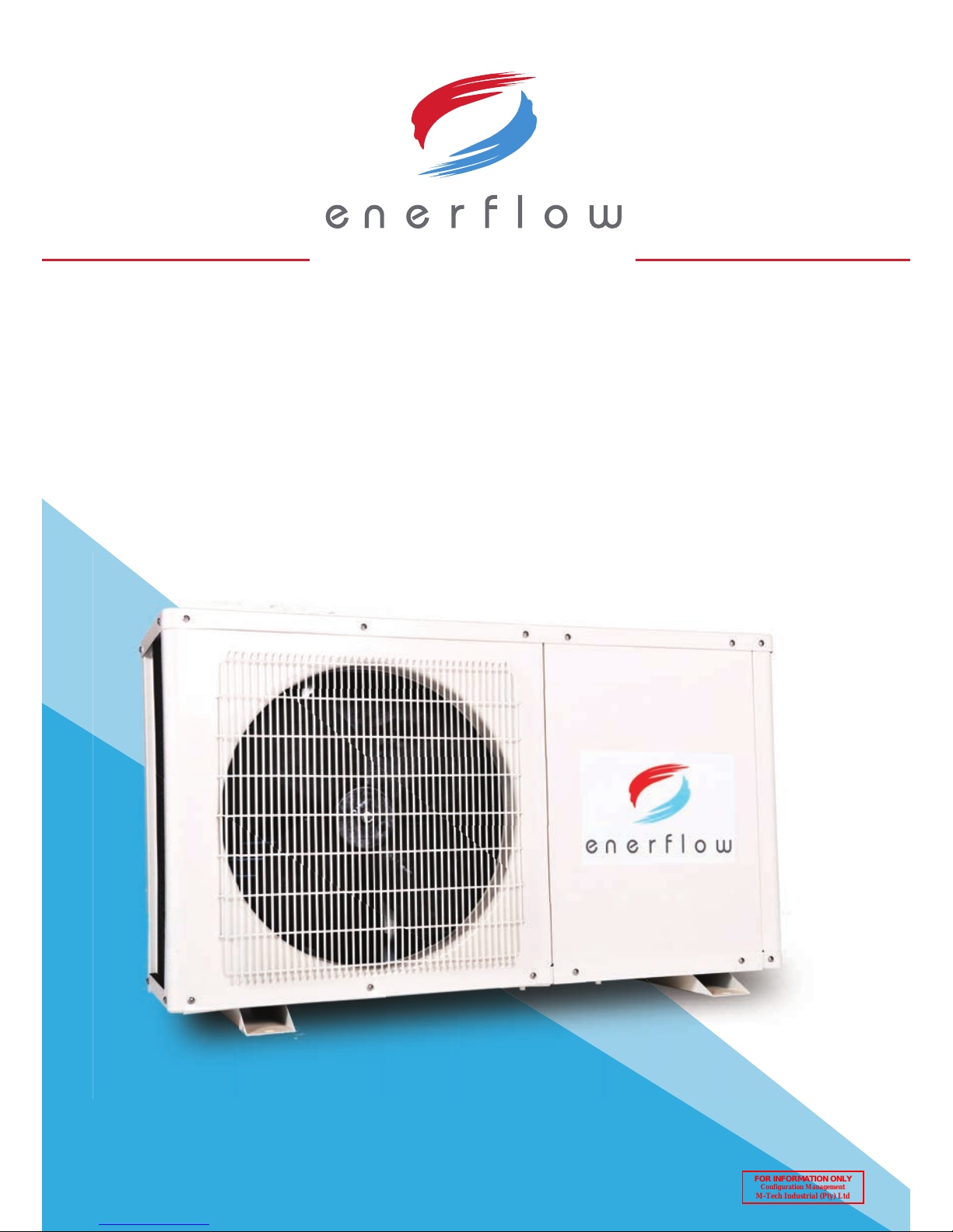
Residential Heat Pump
www.enerflow.co.za
M-Tech Industrial
24 Totius street, Totius Park,
Potchefstroom, South Africa
+27 (0)18 297 0326/7
+27 (0)18 297 0318
rhp@enerflow.co.za
Tel:
Fax:
Email:
SWIMMING POOL
HEAT PUMPS
Harvests free thermal energy
from the atmosphere and
transfers it to your pool.
USER GUIDE
Please read this guide before
operating the heat pump
GENERATION 5
FOR INFORMATION ONLY
Configuration Management
M-Tech Industrial (Pty) Ltd

2
Table of contents
MTRHP-AH1-0009-Rev2
Table of contents 2
1. SAFETY CAUTIONS AND WARNINGS 3
2. HEAT PUMP CONTROLLER FUNCTIONS 4
2.1 Controller and Button Functions 4
2.2 Heat Pump Modes 4
2.3 Setting the Time & Day 6
2.4 Timer Function 6
3. ELEMENT BACK-UP 8
4. LEGIONELLA DISINFECTION CYCLE 9
5. MICRO CIRCULATION FUNCTION 10
6. HEAT PUMP OPERATING PARAMETERS 11
6.1 Changing Parameters 13
7. MAINTENANCE AND SERVICING 15
7.1 Self-maintenance by the user 15
7.1.1 Cleaning the strainer 15
7.1.2 Other general maintenance considerations 16
7.2 Annual service performed by the installer 16
7.3 Heat pump self-protection codes 17
8. OPTIMISE ENERGY SAVINGS 20
8.1 How it works 20
8.2 How to optimise energy efficiency 21
8.3 Suggested timer settings 22
RESIDENTIAL HEAT PUMP WARRANTY 23
Warranty Conditions 23
INSTALLATION HANDOVER CERTIFICATE 25
PERFORMANCE SPECIFICATIONS 27
FOR INFORMATION ONLY
Configuration Management
M-Tech Industrial (Pty) Ltd

3
SAFETY CAUTIONS AND WARNINGS
!
WARNING It is the responsibility of the user to operate and use the heat pump
according to the instructions detailed in this guide. The user shall ensure that the
health and safety of any other person in the area or site near where the heat pump is
installed is not endangered by his conduct or activities when operating the heat pump.
The user is responsible to prevent any tampering with the heat pump.
!
WARNING This appliance is not intended for use by persons (including children)
with reduced physical, sensory or mental capabilities, or lack of experience and
knowledge, unless they have been given supervision or instruction concerning use of
the appliance by a person responsible for their safety. Incorrect handling can cause a
serious hazard depending on the situation.
!
WARNING Ensure that the electricity installation complies with local standards
and regulations. This appliance must be installed in accordance with the national
wiring regulations as contained in SANS 10142.
!
WARNING Do not turn off main power supply to the heat pump during a vacation
or if not in use. The heat pump must have electricity in order to protect itself during
cold climate conditions. It is recommended that the target temperature be set to 25
°C in order to save electricity during prolonged periods of non-use.
!
CAUTION Installation and maintenance must only be performed by qualified
personnel who are familiar with local codes and regulations.
!
CAUTION Note that the unit contains a rotating fan that may cause injury if the
protective grid is removed. Ensure not to touch or work on the unit while in operation.
!
WARNING Children should be supervised to ensure that theydo not playwith the appliance.
!
WARNING Ensure that the electricity/power supply is switched off before any
installation work begins. Note that electric shock is dangerous and can cause death.
!
WARNING Do not turn the unit off and immediately on again. Allow 30 seconds
for the refrigerant pressure to equalize. Do not disconnect/connect power while heat
pump is in operation.
!
CAUTION There are some sharp edges within the unit that may cause injury.
1
FOR INFORMATION ONLY
Configuration Management
M-Tech Industrial (Pty) Ltd

4
HEAT PUMP CONTROLLER FUNCTIONS
Your Enerflow heat pump makes use of an intelligent LCD controller. This controller
can be used to inform the user of certain parameters and change settings on the heat
pump unit. The changes that can be made with this controller include the following:
• Changing the desired water temperature;
• Setting up the timers and
• Activating the electrical element for fast heating mode.
Below is a depiction of the controller interface and buttons:
Controller and Button Functions
2.1
Once the system is switched on at the main power distribution board (DB), the
intelligent controllerwill start up and display the initialization phase for a few seconds
after which the time will be displayed as 00:00. The unit is now in standby mode and
ready for operation.
Desired water
temperature
Time
Heating with
electric element
Heating with
heat pump
Timer active
Current water
temperature
2
Display Name Function
Power Switches the heat pump between heating mode and standby mode.
Mode Activates the fast heating mode by also engaging the geyser element.
Arrows Used for changing the current setting up or down.
Settings Used to change the time, day or parameter settings of the unit.
Clock Used for activating and setting up timers.
Heat Pump Modes
2.2
FOR INFORMATION ONLY
Configuration Management
M-Tech Industrial (Pty) Ltd

5
Heating
Mode
Fast
Heating
Mode
The user can select between standby mode and heating mode by pressing the Obutton.
The user can also activate a fast heating mode by pressing the Mbutton.
This will activate both the backup element inside the geyser and the heat pump to
work simultaneously to heat the water.
NOTE:
Fast heating mode activates the electrical element which will lead to more
energy consumption and should only be used in the exemption when reheating time
needs to be reduced due to a temporary higher demand of hot water.
!
WARNING Do not turn off main power supply to the heat pump during a vacation or
if not in use. The heat pump must have electricity in order to protect itself during cold
climate conditions. It is recommended that the heat pump is placed in standby mode
with all timers removed and the target temperature set at 25°C to keep the heat pump
from heating the water.
Initialization phase Ready for Operation
FOR INFORMATION ONLY
Configuration Management
M-Tech Industrial (Pty) Ltd

6
Timer Function
2.4
The Enerflow heat pump has intelligent control that can be optimised to run more
efficiently and also be adjusted to suit the user’s daily routing. As part of this control,
the time zones that the heat pump may operate in needs to be set up. The following
steps will help you to set the Day and Time settings required for the timer.
1. Press the SET button once.
(The Day will now be flashing.)
2. Make use of the buttons to change the Day.
(0=Sunday, 1 = Monday…6=Saturday)
3. Press the SET button again to acknowledge the Day
setting and continue to the Hours setting.
(The Hour position will now be flashing.)
4. Make use of the buttons to change the Hour.
(Change to the current Hour)
Press the SET button again to acknowledge the
Hours setting and continue to the Minutes setting.
(The Minutes position will now be flashing.)
5. Make use of the buttons to change the Minutes.
(Change to the current Minutes.)
6. Press SET to acknowledge the Minutes setting.
Time Setting
NOTE:
To lock or unlock the intelligent controller, press and hold the button and
the SET button simultaneously for a few seconds.
The Enerflow heat pump can be set to only run during specific periods of the day. This
function allows the heat pump to adjust to the user’s daily routine and ensures that
hot water is available when it should be. This function also ensures that the heat pump
can be set to operate mainly during the hottest part of the daywhen it is most efficient
and thus saving as much energy as possible.
Follow the steps below to set the Timer Function:
1. Press the button once to enter Timer 1 ON slot.
(The Hours and the “1 ON” sign will flash.)
2. Make use of the buttons to set the Hour.
(Set to the first start-up Hour)
Setting the Time & Day
2.3
FOR INFORMATION ONLY
Configuration Management
M-Tech Industrial (Pty) Ltd

7
COLUMN 1
Time Zone 1
COLUMN 2
Time Zone 2
COLUMN 3
Active Time Zone
ON at 08h00
OFF at 23h00
ON at 04h00
OFF at 09h00
ON at 04h00
OFF at 09h00
Follow the steps below to cancel the Timer Function (thus allowing the heat pump to
reheat the water as and when required during a 24 hour day):
1. Press the button.
2. Press the SET button.
3. Repeat steps 1 and 2 four times to cancel all 4 time settings (1 ON, 1 OFF, 2 ON
and 2 OFF.
NOTE:
•
It is possible to decrease your saving by setting your timers incorrectly (such as
letting the heat pump operatre during the coldest part of the day).
•
The heat pump will operate even without any timers being engaged.
•
For energy efficient timer settings please see Section 9: How to optimise energy savings.
The heat pump will therefore only run between 4 AM and 9 AM irrespective of the first
time Zone allowing it to run till 11 PM
NOTE:
Time zones in the Timer Function are NOT allowed to overlap.
The table illustrates an incorrect timer setting where time zone 1 and time zone 2
overlaps with a resulting allowed operational time in column 3
3. Press the button to acknowledge the Hour
setting and continue to the Minutes setting.
(The Minutes and the “1 ON” sign will flash.)
4. Make use of the buttons to set the Minutes
parameter. (Set to the first start-up Minutes)
5. Press the button to acknowledge the Minutes
setting and continue to the “1 OFF” Hour setting.
(The Hours and the “1 OFF” sign will flash.)
6. Make use of the buttons to set the Hour.
(Set to the first shutdown Hour)
7. Press the button to acknowledge the Hour setting and continue to the
Minutes setting.
(The Minutes and the “1 OFF” sign will flash.)
8. Make use of the buttons to set the Minutes.
(Set to the first shutdown Minutes)
9. Press the button to acknowledge the Minutes setting and continue to the
“2 ON” Hour setting.
(The Hours and the “2 ON” sign will flash.)
10. To set up the second time zone, repeat steps 2 to 7 above for “2 ON” and “2 OFF”.
Timer
Active
FOR INFORMATION ONLY
Configuration Management
M-Tech Industrial (Pty) Ltd

8
The Enerflow heat pump is equipped with the intelligent function to use the electrical
element located in the geyser as a backup system. This is to ensure that the user will
have hot water even in the adverse event where the heat pump has entered into self-
protection caused by an external event (such as too low or too high electrical supply
voltage). During such an event the Enerflow heat pump will display the corresponding
Error Code (see Trouble Shooting section of this guide) and an audible “Beep” will be
heard to ensure the usertakes note of the fault. The backup element will automatically
be actived during such an event.
In the unlikely event where the heat pump is struck by lightning for instance, the
intelligent controller may not function properly anymore. In such an event, the
Enerflow heat pump is also equipped with an electrical cross-over switch (located
on the side panel of the heat pump) which can be used to bypass the heat pump
completely. By turning the switch from the default Auto position to the ON position
redirects the electrical power away from the intelligent controller directly to the
electric element (Auto = Heat pump operation, On = Backup element only). Once the
power is switched over to the electric element, it will be controlled by the element
thermostat to heat the water inside the geyser to the thermostat set-temperature.
ELEMENT BACK-UP
3
Electric
Element
only
Heat
Pump
Mode
!WARNING Always ensure that an appropriate and approved geyser thermostat is
installed. When the cross-over switch is engaged, electrical power to the control of
the heat pump is removed. The heat pump will not be able to protect itself during
extremely cold weather conditions (<3°C) and it is therefore recommended that an
authorised installer is contacted as soon as possible to determine the fault and switch
the heat pump back to Auto after the fault has been rectified.
!WARNING Take note that if the thermostat temperature may be set higher than the
heat pump set temperature. The resultingwaterthen be hotter and could cause scalding.
NOTE:
The cross-over switch can be used to remove the “Beeping” sound without
disengaging the element. Please write down the self-protection error code before
switching the cross-over switch so that the installer may be informed of what
caused the error.
FOR INFORMATION ONLY
Configuration Management
M-Tech Industrial (Pty) Ltd

9
The Enerflow heat pump has the ability to disinfect your geyser once a week (Monday
mornings at 02h00) from bacteria such as Legionella*. During this process the
heat pump will automatically be started to heat the water to 55°C where after the
electric element will be activated until the target temperature (set in parameter
6** - recommended 60°C) is reached (geyser thermostat set to 60°C as default
during installation). This temperature will be maintained for the time period as set in
parameter 7 (10 to 30 min).
NOTE:
During the Disinfection Cycle the sign will flash on the LCD controller:
* The pathogenic Gram-negative bacterium that grows in central heating and air conditioning
systems at a certain temperature that can cause Legionnaires’ disease.
** Standard geyser maximum temperature is 75°C controlled by the thermostat.
For more information please visit
www.health24.com/Medical/infectious-diseases/Bacterial-infections/Legionnaires-disease-20120721-2
!
WARNING When this function is set to activate, the water may be hotter than 55°C
and may result in scalding. Adequate care should be taken to prevent scalding in small
children or individuals with mental impairment.
Legionella Disinfection Cycle 4
FOR INFORMATION ONLY
Configuration Management
M-Tech Industrial (Pty) Ltd

10
!WARNING All plumbing installations must complywith local standards, regulations
and bylaws. Refer to the latest versions of SANS 1352, SANS 10252, SANS 10254
NOTE:
•
Ring-main systems are less energy efficient due to higher thermal losses in the circulation pipes.
•
To minimise thermal losses it is very important that the circulating piping in the ring-main
system be insulated properly with at least R-1 rated lagging. In the case of a 20mm (3/4
inch) pipe, R-1 rated lagging has a thickness of about 25mm.
5MICRO CIRCULATION FUNCTION
Your Enerflow heat pump has the functionality of heating a central, ring-main water distribution
pipeline. This function is used to ensure that hot water is supplied throughout the residence as
an instant hot-water-on-tap solution. The installer will ensure that the commissioning valve on
the return line is set to an approximate 10% bypass (i.e. closed 90%). Activate the micro circu-
lation function by changing Parameter 8 to the value of 1 (see section on Heat Pump Operating
Parameters) on the intelligent controller. With this function enabled, the water pump will run for
40 seconds during the period set in Parameter 9 (adjustable between 2 and 60 minutes). Thus, if
Parameter 9 is set to 10, the heat pump will start the water circulation pump every 10 minutes for
the predefined 40 seconds. Depending on the volume of water in the ring-main, the Parameter
9 interval should be adjusted accordingly (more volume = smaller intervals to ensure that the
water is kept at the desired temperature).
Micro Circulation Function
(See Section 3.8)
0 = function off;
1 = function on.
FOR INFORMATION ONLY
Configuration Management
M-Tech Industrial (Pty) Ltd

11
Heat Pump Operating Parameters
The heat pump operation is governed by 22 input parameters. Some of the operating parameters
may be adjusted by the user if required. The remainder of the parameters are set by the qualified
installer and should not be changed. The function and range of all the parameters are explained
in the following table:
Param-
eter Description Range Default Remark
0Target water temperature* 25 ~ 75°C 55°C Adjustable
1
Set temperature difference
- Difference between actual
measured water temperature at
the position of the heat pump
temperature probe and set/
required water temperature. (The
smaller the difference, the more
frequently the heat pump restarts)
2 ~ 5°C 5°C Adjustable
2 Defrosting interval 30 ~ 90 min 40 min Do not change
3Temperature at which defrosting
operation starts -30 ~ 0°C -7°C Do not change
4Temperature at which defrosting
operation stops 2 ~ 30°C 13°C Do not change
5 Duration of defrosting operation 2 ~ 12 min 8 min Do not change
6Target water temperature for
disinfecting cycle 60 ~ 90°C 60°C Adjustable
7 Duration of disinfecting cycle 10 ~ 120 min 30 min Do not change
8Micro circulation function
(Off = 0; On = 1) 0 / 1 0 Adjustable
9 Micro circulation cycle interval 2 ~ 60 min 2 min Adjustable
10 Installer function 1 ~ 10 min 3 min Do not change
11 Installer function 70 ~ 100°C 90°C Do not change
12 Installer function 5 ~ 30°C 20 °C Do not change
13 Compressor discharge protection
temperature 90 ~ 125°C 115°C/b5 Do not change
14 Temperature for exiting the
compressor discharge protection 5 ~ 30°C 30°C Do not change
6
FOR INFORMATION ONLY
Configuration Management
M-Tech Industrial (Pty) Ltd

12
*A maximum water temperature of 55°C can be reached by the heat pump without using auxiliary
heaters. However, if the target temperature is set between 55°C and 75°C the electric heater will
be activated above 55°C to reach this temperature.
Param-
eter Description Range Default Remark
15 Heat pump auto restart mode
(Off = 0; On = 1) 0 / 1 1 Adjustable
16 Starting temperature for defrosting
evaporator -9 ~ 10 °C 4°C Do not change
17 Beeper (Off = 0; On = 1) 0 / 1 1 Adjustable
18 Disinfecting cycle (Off = 0; On = 1) 0 / 1 1 Do not change
19 Geyser temperature measurement
probe offset -10 ~ 10°C 3°C Do not change
20 Automatic geyser temperature
measurement probe offset
0 (fixed) / 1
(calculated) 0 Do not change
21 EEV setting 0 - 5 0 - 5
See remarks at
the end of the
table
22 HP temperature measurement
probe offset -5 ~ 5 °C 3 °C Do not change
AWater temperature -9 ~ 90°C Reading Temperature
output
BEvaporator coil temperature -9 ~ 90°C Reading Temperature
output
CCompressor discharge temperature 0 ~ 127°C Reading Temperature
output
DAmbient temperature -9 ~ 90°C Reading Temperature
output
EHeat pump return water
temperature -9 ~ 90°C Reading Temperature
output
FElectronic expansion valve
operating parameter 0 ~ 50 Reading Valve open
output
FOR INFORMATION ONLY
Configuration Management
M-Tech Industrial (Pty) Ltd

13
Remarks
• Parameter 0 – It is advised to set the target temperature at 55°C.
• Parameter 1 – Temperature difference between target and measured
temperature before heat pump starts. Recommended to set this at 5°C.
• Parameter 13 – It is advised to set the temperature at 115°C which is indicated as b5.
• Parameter 14 – It is advised to set the temperature at 30°C
• Parameter 21 – Parameter 21 should be set to a specific number with regards
to the unit you have:
• Parameter 21 should be set as “1” for ERHP-SU08E-MS;
• Parameter 21 should be set as “2” for ERHP-SU14E-MS & ERHP-SU14E-PL;
• Parameter 21 should be set as “3” for ERHP-SU08E- PL;
• Parameter 21 should be set as “4” for ERHP-SU20E-MS & ERHP-SU20E-PL;
• Parameter 21 should be set as “5” for ERHP-SU26E-MS.
To adjust or change the parameter settings, follow the steps below:
If the target temperature needs to be changed, parameter 0 can be modified as
explained in the steps or alternatively the user can simply press the buttons.
1. Press the Power Obutton to engage standby mode.
(The picture of the sun will no longer be on the display)
2. Press and hold the SET button for 3 seconds.
(Display will “Beep” and parameter number “00” and the current setting “55°C”
will flash)
Current water
temperature
Target water
temperature
Changing Parameters 6.1
Parameter 1: Temperature difference
before heat pump starts:
2°C = Heat Pump Starts More Frequently
5°C = Heat Pump Starts Less Frequently
FOR INFORMATION ONLY
Configuration Management
M-Tech Industrial (Pty) Ltd

14
1. Make use of the buttons to select between the different operating parameters.
2. To change an operating value, press the SET button once. (Quickly)
(The parameter number “At the bottom” will not be flashing anymore, but the
current setting “Indicated between the lines” will continue to flash)
Note: If both continue to flash, please ensure the heat pump is in Standby mode.
3. Make use of the buttons to change the value to the desired or default value.
4. Press the SET button to confirm the setting and return to selecting an operating parameter.
(To change the values of these parameters, repeat steps 3 to 6.)
5. To exit this mode automatically, wait for 5 seconds without pressing any buttons
or press the Obutton to exit manually.
FOR INFORMATION ONLY
Configuration Management
M-Tech Industrial (Pty) Ltd

15
The following maintenance should be done by the user at least quarterly. In areas
where excessive debris is present in thewater (i.e. at construction sites or where repairs
were done on municipal water lines) more frequent maintenance may be required.
Before undertaking any maintenance on the heat pump, engage the Standby Mode as
indicated in section 3.2 Heat pump modes.
The strainer can be cleaned by using the diagram above and following the steps listed below:
1. Close the outlet and inlet ball valves at the heat pump.
2. Remove the Bonnet of the strainer by using the correct size spanner.
3. Remove the strainer element or Sieve.
4. Rinse and clean the strainer element under running water by slightly opening the
inlet ball valve.
5. Reinsert the strainer and close the Bonnet hand tight only.
6. Open the outlet ball valve slightly to allow any air that may have entered into the
heat pump to be released through the strainer.
7. Close the bonnet completely now by using the correct size spanner again.
8. Open the ball valves to the full open position.
7
Maintenance and Servicing
Self-maintenance by the user 7.1
Cleaning the strainer 7.1.1
Outlet ball valve
Strainer element
Bonnet
Strainer
Inlet ball valve
FOR INFORMATION ONLY
Configuration Management
M-Tech Industrial (Pty) Ltd

16
Other general maintenance considerations
Annual service performed by the installer
7.1.2
7.2
• Clear away any objects or trim vegetation that is within 500mm from the heat
pump unit and that could restrict air flow into the heat pump.
• The airway of the fan and the evaporator needs to be cleaned at least annually to
ensure effective airflow and heat transfer. If any obstruction such as cobwebs,
leaves and the like on the outside of the heat pump is observed, clear this out
immediately. Do not use a high pressure water hose to spray down the unit; the
heat exchanger fins may be damaged.
• Ensure that all the parameters are set correctly.
Although your Enerflow heat pump is a self-contained and reliable means of providing
eco-friendly hot water, an annual service is required to ensure efficient performance
and that warranty conditions are met. The following items must be checked:
• Ensure that the water supply pressure and flow rate is sufficient at all times.
• Ensure that the geyser tank probe is still correctly inserted and fastened into the
geyser probe pocket or onto the geyser flange.
• Open and service the water circulation pump.
• Ensure that water drainage holes in the heat pump base plate are not blocked.
Water build up in the base of the heat pump unit could lead to premature rust
and damage internal components.
• Service the heat pump Diverter Valve.
• Test the Back-up element to ensure that it is still in a good working condition.
• Descale the heat pump unit using a non-industrial descaling fluid such as Brown
Vinegar or Kettle Cleaner.
• Ensure the refrigerant charge (i.e. amount of gas insidethe heat pump) is still sufficient.
• No maintenance needs to be performed on the internal refrigerant components
of your Enerflow heat pump.
• The unit is designed with a close loop refrigerant cycle that does not need short
term maintenance or service under normal operation.
• Ensure that the system is drained completely of water if it is not going to be used
in the winter in order to avoid a pipe from bursting due to freezing.
FOR INFORMATION ONLY
Configuration Management
M-Tech Industrial (Pty) Ltd

17
NOTE:
The service operations as described in the section above shall only be carried
out by qualified installer/personnel who are well trained within their respective fields.
In areas where hard water conditions are present, this service may need to be per-
formed more frequently (such as every 4-6 months).
Fault/Error Possible Cause Recommended
Action/Remark
Heat pump
does not start.
• Geyser temperature is
(<55°C).
• Circuit breaker off.
• Heat pump protection Error.
• Loose electrical connections.
• Unit failure.
• Check water temperature.
• Check Circuit Breaker.
• Identify the Error and attempt to correct.
• Contact an Electrician.
• Contact the Installer.
Fan does not
work
• High air temperature (> 35°C).
• Physical obstruction.
• Fan failure.
• Check the air temperature
• Check if the fan rotates freely and that no
restrictions are present.
• Contact the Installer.
Heat pump
works with
insufficient
heating.
• Very cold air temperature
(<2°C).
• Finned coil is dirty.
• Obstacle blocks air inlet/
outlet.
• Fan not running.
• Check the air temperature.
• Clean the finned coil as per maintenance
section.
• Remove the obstacle.
• Contact the installer.
P01 Water inlet temperature sensor
failure.
In case of any of these failures the
Installer must be contacted to check
the connections and replace sensor if
required.
P02 Evaporator coil temperature
failure.
P03 Compressor discharge
temperature sensor failure.
P04 Ambient temperature sensor
failure.
P05 HP Switch failure.
P06 LP Switch failure.
P07 Too high compressor discharge
temperature.
• Switch off main power supply to the
heat pump, wait 30 seconds and switch
on again.
• Clean strainer and open a hot water tap to
flush/prime the water lines.
• Check municipal water supply pressure.
• Contact the installer to open and clean
water circulation pump.
Heat pump self-protection codes 7.3
NOTE:
Please make use of the following table to do troubleshooting if an error or fault
occurs. If the problem persists shut down the system and switch off the main power
supply or activate the crossover switch as described in this guide. Hereafter, contact
your installer for assistance.
FOR INFORMATION ONLY
Configuration Management
M-Tech Industrial (Pty) Ltd

18
Fault/Error Possible Cause Recommended
Action/Remark
P08 First class anti-freeze
protection.
Error will automatically disappear after
ambient temperatures rises.
P09 Second class anti-freeze
protection.
Error will automatically disappear after
ambient temperatures rises.
P10 Water level sensor failure. Contact the installer.
P11 Overload protection. Contact the installer.
P12 Heat pump return water temp.
failure.
In case of any of these failures the
Installer must be contacted to check the
connections and replace sensor if required.
E01 Phase protection sensor failure. Contact the installer.
E04 Phase rotation detected. Contact the installer.
E05 HP switch protection.
• Electric element will be activated
automatically.
• Switch off main power supply to the
heat pump, wait 30 seconds and switch
on again.
• Clean inline water strainer.
• Check municipal water supply pressure.
• Contact the installer to open and clean
water circulation pump.
E06 LP switch failure. Contact the installer.
E07 Too high compressor discharge
temperature.
• Switch off main power supply to the
heat pump, wait 30 seconds and switch
on again.
• Clean strainer and open a hot water tap
to flush/prime the water lines.
• Ensure that the fan is not restricted by
dirt or leafs.
• Check municipal water supply pressure.
• Contact the installer to open and clean
water circulation pump.
E08 Communication failure.
• Reconnect LCD display unit extension
cable.
• Ensure the plugs has a proper connection.
• Contact the installer.
Defrosting sign
indicating Defrosting mode activated. Heat pump will continue with normal
operation after defrosting is completed.
NOTE:
If any of the errors above appear frequently, contact your installer.
FOR INFORMATION ONLY
Configuration Management
M-Tech Industrial (Pty) Ltd

19
PLEASE NOTE THE FOLLOWING:
1.
Outdoor temperature, water inlet temperature and parameter settings may
affect the performance and power consumption of the heat pump unit.
2.
Ensure that the heat pump air flow is not blocked.
3.
If the ambient temperature is too high, the fan may stop working temporarily in
order to protect the system. The heat pump will however still provide hot water
to the geyser. If the temperature decreases the fan will resume operation again.
4.
If the unit enter the defrosting mode the fan may stop working temporarily.
Once the evaporator coil temperature has reached an acceptable level, the fan
will resume operation.
5.
Ensure that the unit is well ventilated and that no cold air is redirected back into
the evaporator (i.e. do not install the heat pump in small enclosed rooms).
6.
Ensure that all the isolation valves are open before the heat pump is turned on.
FOR INFORMATION ONLY
Configuration Management
M-Tech Industrial (Pty) Ltd

20
optimise energy savings
8
In this section the basic functioning of a heat pump is explained to enable the user to
optimise the energy savings of the heat pump.
The Enerflow heat pump uses an air-source-vapour-compression-cycle to transfer
heat from ambient temperatures in the atmosphere to the water in a geyser. A
refrigeration/gas cycle is normally made up of four components (Evaporator,
Compressor, Condenser, and Expansion Valve) each with a very specific function.
Below is a depiction of such a gas
cycle that interacts with a water
circulation cycle similar to what
can be found in the Enerflow heat
pumps. The picture below (for
illustration purposes only) shows
the major components and is used
to briefly explain how they interact
to deliver energy efficient hot
water. The evaporator is used as
a heat exchanger that enables heat
transfer from the warmer ambient
air to the colder gas inside the
evaporator tubes. An electric fan is
used to ensure the air is drawn over
the evaporator fins and enhance
heat transfer. This absorbed heat/
energy is then further intensified
(i.e. more energy added) by passing
the gas through the compressor which increases the pressure and temperature of the
gas cycle. This high-pressure-high-temperature gas is then able to transferthe energy
to the water through a second heat exchanger, the condenser. The water from the
geyser is pumped through the condenser where it collects the energy in the condenser
tube, transfers it to the water and thereby heating it. Finally the cooler-high-pressure
gas is passed through an intelligently controlled expansion valve that rapidly lowers
the gas pressure and temperature. This low-pressure-low-temperature gas is then
passed to the evaporator where energy can once again be harvested from the warmer
atmospheric air. This closed loop cycle operation will continue until the water in the
geyser is at the heat pump set temperature. At this stage the intelligent controller
will turn off the components in a specific protective sequence and put the heat pump
in standby.
(Picture reference http://aboutyourrefrigeration.blogspot.com)
How it works
8.1
FOR INFORMATION ONLY
Configuration Management
M-Tech Industrial (Pty) Ltd
Table of contents
Other Enerflow Heat Pump manuals
Popular Heat Pump manuals by other brands

Lennox
Lennox HSXA16-024 installation instructions

Zodiac
Zodiac Pac Alpha 5M Instructions for installtion and use

Miele
Miele PDR 908 HP Marine Operating and installation instructions

BWT
BWT PEARL HPF instruction manual

Zodiac
Zodiac PX 50 Instructions for installation and use

GE
GE Zoneline AZ35H09E5B Specifications

Daikin
Daikin FTXR28EV1B9 Service manual

Heat Controller
Heat Controller B-VFH09MA-1 Installation, operation & maintenance manual

CIAT
CIAT AQUACIAT POWER ILD Series instruction manual

Atlantic
Atlantic Alfea Evolution 5 Installation and operating manual

Carrier
Carrier COMFORT SERIES 25HCC5 Installation instructions manual

Nortek
Nortek PSH4BE user manual